International Conference “INTELINC 18”, 12th & 13th October 2018
239
Dual Band H-Shaped Microstrip Patch Antenna for WLAN and
WiMAX Applications
E. Aravindraj
1*, T. Kaviarasan
2, A. Kannan
3, Dr. K. Ayyappan
41, 2, 3, 4
Dept. of ECE, Rajiv Gandhi College of Engg & Tech, Pondicherry, India
1
[email protected], [email protected],
4
ABSTRACT- Microstrip patch antenna (MPA) provides a smart way to utilize dual spectrum of frequencies
simultaneously. Here, an H-shaped patch is designed with slots etched on it and also a defective ground structure (DGS) is created on ground surface. This type of slotted design leads the antenna simultaneously generate a dual band of frequencies for the given input. The dual frequencies are 2.4 GHz and 3.5 GHz used in Wireless Local Area Network and Wireless Metropolitan Network. The construction of MPA has a substrate layer which is squeezed between two conductor layers on both sides. The conductor layer 1 or radiating layer is the Patch which is shaped like letter H for improved degree of output parameters and the slots will generate dual frequencies fashion. This radiating layer is situated on the Flame Retardant 4 (FR4) substrate which enables the radiation in the antenna. Then, the DGS on the ground structure will improve bandwidth. The MPA is symmetrical and input is fed using a microstrip feed through a lumped port. The dimensions of the designed antenna are 44×52×1.6mm. Hence, the provided antenna design has some better parameter value with high efficiency for both the frequencies.
Keywords: Dual Band, H-shaped microstrip patch, Etching slots, DGS, FR-4 Substrate, WLAN and WiMAX.
1. INTRODUCTION
MPA have achieved greater advancement. Comparing with other antennas, MPA have several merits like easy fabrication, compact, low profile, less expensive etc [1]. MPA systems are essentially used in smart way at future communication systems [2-4]. WLAN is a connection made inside certain area where the hosts are connected without any wires. WLAN provides flexibility in deployment functions in giving good services to the host.
It provides a platform for connecting various hosts in a group wirelessly within a relatively small space. WMAN provides access to a network in buildings using exterior antennas connected to base stations. WiMAX is portable broadband internet connectivity around cities with high speed. It uses cell base transceivers for providing service to longer area [5]. Slots are etched on the patch for improving reflection coefficient [6, 7]. Thus, the proposed antenna design has a better return loss and bandwidth value. FR4 is a dielectric with a constant 4.4 which are widely used in MPA’s for their easy
availability [8, 9]. The dimension of the FR4 substrate is 44×52×1.6mm. Here, ADS is the design automation software tool for designing antenna and implementing them in the RF circuits. It also provides platform for RF, microwave, and high speed digital applications [10, 11]. In this paper, an H-shaped MPA with DGS is presented. Hereby, the antenna’s structural parameters are follows; Section II elaborates the structure and geometry of the constructed antenna that includes patch, substrate and Ground structure information and also the implementation of slots and DGS in the MPA are presented. Section III brings out antenna parameters through simulation outputs. Section IV concludes with the merits of the paper.
2.
STRUCTURE
OF
ANTENNA
240
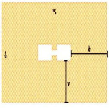
2.1 SLOTTED H-SHAPED PATCHRadiating layer is the patch which is shaped like letter H for improved degree of output parameters and the slots will generate dual frequencies fashion. The H-shaped design of the patch will improve the efficiency and the surface current. Etching slots S1 and S2 reduces reflection
loss and helps the antenna to radiate dual frequencies [13, 14].
Fig. 1 H-shaped patch with Microstrip feed
2.2 DIELECTRIC AND GROUND LAYER
Fig. 2 Position of H-shaped DGS
Substrate used in the design is FR4 ( = 4.4) used as substrate and ground plane used is copper (Cu) [15, 16]. The Fig. 3a and b shows the design of
Slotted H-shaped MPA with DGS. As shown in Fig. 2, the ground structure design of antenna consist of a Dumbbell shaped DGS which is placed at 14 mm and 19 edges. The ground plane dimensions are 44 x 52 mm metal patch provides best results for the simulated antenna design.
2.3 METHEDOLOGY AND DESIGN
Patch Width
:
W
=
√
(1)
Where, c - Velocity of light
Effective Dielectric Constant:
(
)
⁄(2)
Patch Length Extension:
( ) (
)
(3)
Effective Patch Length:
√
(4)
Patch Length:
(5)
Substrate Width( ) Ground plane width( ):
(6)
Ground Plane length ( ) Substrate length ( ):
(7)
241
Fig. 3b 3D view of the designed MPATable I. Dimensions of H-shaped MPA
Antenna
The parameters of the design are obtained using the simulations on the ADS software as in Table. I. The optimized H-shaped MPA is shown in the Fig. 3a and b. A single antenna is used in dual applications and provides more advancement in the antenna design [17].
3.1 RETURN LOSS
The return loss is rays reflected back by the obstacle to the antenna which affects the radiation generated. It should be less because the power radiated by the antenna will be reflected back due to higher return loss. Fig. 4 shows the return loss for MHz ranges from 2.253 GHz to 2.617 GHz for 2.4 GHz and 215 MHz ranges from 3.406 GHz to 3.621 GHz for 3.5 GHz. A return loss of -10 dB is enough for the antenna to operate efficiecntly [18]. So the antenna bandwidth is measured at -10 dB value of S11as shown in Fig. 5a and b.
Fig. 5a Bandwidth for 2.4 GHz
242
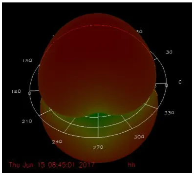
3.3 RADIATION PATTERN
Radiation pattern is the antenna’s radio wave strength in a certain direction. The radiation pattern for dual band is shown in Fig.7a and b.
Fig. 6a Radiation pattern for 2.4 GHz
Fig. 6b Radiation pattern for 3.5 GHz
3.4 GAIN AND DIRECTIVITY
The Gain is the capability of antenna to change electrical signal to radiating radio waves. Directivity is the density of power that a can antenna radiated in a respective direction. The Fig. 6a represents the gain and directivity values for 2.4 GHz is 3.968 dB and 3.963 dB respectively. The Fig. 6b shows 3.556 dB and 5.103 dB of gain directivity respectively.
Fig. 7a Gain and Directivity for 2.4 GHz
Fig. 7b Gain and Directivity for 3.5 GHz
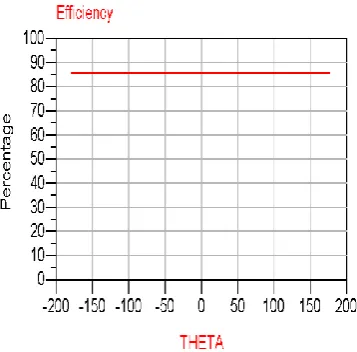
3.5 EFFICIENCY
Efficiency is the power retrieved by the end user to the power radiated. The Fig. 8a and b efficiency value of 90% and 86% for dual frequencies.
243
Fig. 8b Efficiency of 3.5 GHz3.6 IMPEDANCE MATCHING
The lumped port’s structure and the transmission lines impedance should be close to each other. As shown in Fig. 9a and b, the impedance of the antenna is 50 ohms. The Table II represents the obtained simulation results of the MPA.
Table II. Simulated output for Dual band MPA
Frequency 2.4 GHz 3.5 GHz
Return Loss -31.396 dB -30.368 dB
Bandwidth 364 MHz 215 MHz
Gain 3.968 dB 3.556 dB
Directivity 3.963 dB 5.103 dB
Efficiency 90% 86%
Impedance matching
50 Ohms 50 Ohms
4. CONCLUSION
In this paper, the H-shaped MPA is proposed with slots and DGS for radiating dual frequencies such as 2.4 and 3.5 GHz. As given in Table. II, this antenna structure provides good antenna parameters that include a return loss value less than -30 dB; Bandwidth around 200 MHz; Gain and Directivity with acceptable range of 3 dB and 4 dB respectively; with a perfect impedance matching, gain, directivity and wider bandwidth. So, this paper concludes that the slotted H-shaped antennas with DGS will exhibits improved antenna parameters and it operates at dual band (2.4 and 3.5 GHz) simultaneously. This antenna will radiate both WLAN and WiMAX frequencies (i.e.) 2.4 GHz and 3.5 GHz simultaneously with an efficieny of 90% and 86% respectively and it has the potential merits in coverage, less reflection co-efficient, power consumption, wider bandwidth, Matched impedance and efficiency.
Fig. 9a Impedance
244
. REFERENCE
1. Karishma Patkar, Anshul Agarwal, Neelesh Dixit, Colossal Data Analysis and Networking, (2016).
2. E. Aravindraj, K. Ayyappan, International Conference on Computer Communication and Informatics,(2017).
3. M. Karthick, National Conference on Computing, Communication and Information Systems, (2015).
4. M.H. Amini and H.R. Hassani, Electronics Letters, (2013), Vol. 49, no. 17.
5. E. Aravindraj, Dr. K. Ayyappan, Indian Journal of Innovations and Developments, (2017), Vol. 5, no. 2.
6. Fahd Baabdullah, Adnan Affandi, IOSR Journal of Electrical and Electronics Engineering, (2016), Vol. 11, no. 3.
7. E. Aravindraj, Dr. K. Ayyappan, Dr. R. Kumar, International Journal of Electrical and Electronics Engineering, (2017),Vol. 9, no. 1. 8. Anzar Khan, Rajesh Nema, International
Journal of Computer Applications,(2012),Vol. 55, no. 14.
9. Radhouane Laajimi and Ali Ajmi,
International Conference on Control, Decision and Information Technologies, (2016).
10. A. S. U. Constantine A. Balanis, Antenna Theory: Analysis and Design, pp. 811-882. 11. P. Krachodnok, International Journal of
Electrical, Computer, Energetic, Electronic and Communication Engineering, (2014), Vol. 8, no. 7.
12. M. R. Ahsan, M. T. Islam, M. Habib Ullah, The Scientific World Journal, (2014), Vol. 75, no.3. 13. Imad Ali and Ronald Y. Chang, Vehicle
Technology conference, (2015).
14. Anju Verma, Debajit De, S. Nanda and A. Tripathy, International Conference On Computer & Communication Engineering, (2015)
15. Arnab Das, Bipa Datta, Samiran Chatterjee, Moumita Mukherjee, Santosh Kumar Chowdhury, International Conference On Information Communication And Embedded System, (2015).
16. Deepuku M, George J, Broadband dual frequency microstrip antenna, Electronics Letter, (2014).