Efficient Matrix Codes for Error Correction in
Memory
M.Mohankumar
1
,T.Dhivya
2
Assistant professor, ECE Dept, Sri Eshwar college of Engineering,Coimbatore1 E-mail:[email protected]
PG Student, ECE Dept, Sri Eshwar college of Engineering,Coimbatore2 E-mail:[email protected]
Abstract- In CMOS integrated circuits, electronic memories are widely used. As transistor size shrinks, multiple
cell upsets are becoming an increasingly important factor in the reliability of memories exposed to radiation effects. To prevent the MCUs from causing data corruption, more complex error correction codes (ECCs) are widely used to protect memory. Recently, matrix codes (MCs) based on Hamming codes have been used for the memory protection. The decimal matrix code (DMC) based on divide-symbol is used to the enhance memory reliability with lower delay. The DMC utilizes decimal algorithm to obtain the maximum of the error detection capability. Moreover, the encoder-reuse technique (ERT) is used to minimize the area of the extra circuits without disturbing the whole encoding and the decoding processes The DMC is compared to the well-known codes such as the existing Hamming, MCs, and punctured difference set (PDS) codes.
Index Terms—Decimal algorithm, error correction codes (ECCs), mean time to failure (MTTF), memory,
multiple cells upsets (MCUs).
I.INTRODUCTION
As CMOS technology scales down to nano scale and memories are combined with an increasing number of electronic systems the soft error rate in memory cells is rapidly increasing, especially when memories operate in space environments due to ionizing effects of atmospheric neutron, alpha-particle and cosmic rays.
Although single bit upset is a major concern about memory reliability, multiple cell upsets (MCUs) have become a serious reliability concern in some memory applications[1]. In order to make memory cells as fault-tolerant as possible, some error correction codes (ECCs) have been widely used to protect memories against of terrors for years[2]-[4]. For example, theBose–Chaudhuri– Hocquenghemcodes,Reed–Solomon codes and punctured difference set (PDS) codes[5] have been used to deal with MCUs in memories. But these codes require more area, power, and delay overheads since the encoding and decoding circuits are more complex in these complicated codes.
Inter leaving technique has been used to restrain MCUs, Which rearrange cells in the physical arrangement to separate the bits in the same logical word into different physical words. However, interleaving technique may not be
practically used in content-addressable memory (CAM), because of the tight coupling of hardware structures from both cells and comparison circuit structures[6].
Built-in current sensors (BICS) are proposed to assist with single-error correction and double-error detection codes to provide protection against MCUs[7]. However, this technique can only correct two errors in a word.
More recently[8], in 2-D matrix codes (MCs) are proposed to efficiently correct MCUs per word with a low decoding delay in which one word is divided into multiple rows and multiple columns in logical. The bits per row are protected by Hamming code while parity code is added in each column. For the MC[8] based on Hamming, when two errors are detected by Hamming the vertical syndrome bits are activated so that these two errors can be corrected. As a result MC iscapable of correcting only two errors in all cases. In an approach that combines decimal algorithm with Hamming code has been conceived to be applied at software level. It uses addition of integer values to detect and correct soft errors. The results obtained have shown that this approach have a lower delay overhead over other codes.
subtraction) to detect errors. The advantage of using decimal algorithm is that the error detection capability is maximized so that the reliability of memory is enhanced. Besides the encoder-reuse technique (ERT) is proposed to minimize the area overhead of extra circuits (encoder and decoder) without disturbing the whole encoding and decoding processes, because ERT uses DMC encoder itself to be part of the decoder.
. The proposed DMC is introduced and its encoder and decoder circuits are present in Section II. This sectional so illustrates the limits of simple binary error detection and the advantage of decimal error detection with some examples. Finally some encoded and decoded as an example based on the proposed techniques.
A.Proposed Schematic of Fault-Tolerant Memory
The proposed schematic of fault-tolerant memory is depicted in Fig.1. First during the encoding (write) process, information bits are fed to the DMC encoder and then the horizontal redundant bits H and vertical redundant bits V are obtained from the DMC encoder. When the encoding process is completed the obtained DMC code word is stored in the memory. If MCUs occur in the memory. These errors can be corrected in the decoding (read) process. Due to the advantage of decimal algorithm, the proposed DMC has higher fault-tolerant capability with lower performance overheads. In the fault-tolerant memory the ERT technique is proposed to reduce the area overhead of extra circuits and will be introduced in the following sections.
Figure.1 Overall block diagram
B.Proposed DMC Encoder
In the proposed DMC, first, the divide-symbol and arrange-matrix ideas are performed. i.e., the N-bit word is divided into k symbol so fm bits (N =k×m), and these symbols are arranged in a k1×k2 2-D matrix (k=k1×k2), where the values of k1 and k2 represent the numbers of the horizontal redundant bits H are produced by performing decimal integer addition of selected symbols per row. Here, each symbol is regarded as a decimal integer. Third, the vertical redundant bits V are obtained by binary operation among the bits per column. It should be noted that both divide-symbol and arrange-matrix are implemented in logical instead of in physical. Therefore, the proposed DMC does not require changing the physical structure of the memory.
Figure.2 32-bits DMC logical organization (k = 2 × 4 and m = 4). Here, each symbol is chosen simultaneously. H0–H19 are horizontal check bits. V0 through V15 are vertical check bits. However, it should be mentioned that the maximum correction capability (i.e., the maximum size of MCUs can be corrected) and the number of redundant bits are different when the different values for k and m are chosen. Therefore,
k and m should be carefully adjusted to maximize
∗
Figure.3 32 bit structure of decimal matrix code
The horizontal redundant bits H can be obtained by decimal integer addition as follows:
H4H3H2H1H0=D3D2D1D0
+D11D10D8D8 (1)
H9H8H7H6H5=D7D6D5D4
+D15D14D13D12 (2)
And similarly for the horizontal redundant bits H14H13H12H11H10 and H19H18H17H16H15 where “+” represents decimal integer addition. For the vertical redundant bits V, we have
V0 =D0 XOR D16 (3) V1 =D1 XORD17 (4)
And similarly for the rest vertical redundant bits. The encoding can be performed by decimal and binary addition operations from (1) to (4). The encoder that computes the redundant bits using multibit adders and XOR gates is shown in Fig. 3. In this figure, H19−H0 are horizontal redundant bits, V15−V0 are vertical redundant bits, and the remaining bits U31−U0 are the information bits which are directly copied from D31 to D0. The enable signal En will be explained in the next section.
C.Proposed DMC Decoder
To obtain a word being corrected, the decoding process is required. For example, first, the received redundant information bits D∗. Second, the horizontal syndrome bits
H4H3H2H1H0 and the vertical syndrome bits S3−S0 can be calculated as follows:
H4H3H2H1H0=H4H3H2H1H0’
H4H3H2H1H0 (5) S0=V0⊕V0’
(6)
And similarly for the rest vertical syndrome bits,where“−“represents decimal integer subtraction. When H4H3H2H1H0 and S3−S0 are equal to zero, the stored codeword has original information bits in symbol 0 where no errors occur. When H4H3H2H1H0 and S3−S0 are non zero, the induced errors (the number of errors is 4 in this case) are detected and located insymbol0, and then these errors can be corrected by,
D0correct =D0⊕S0 (7)
The proposed DMC decoder is depicted in Fig.4, which is made up of the following sub-modules, and each executes a specific task in the decoding process: Syndrome calculator, error corrector. It can be observed from this figure that the redundant bits must be recomputed from the received information bits D∗ and compared to the original set of redundant bits in order to obtain the syndrome bits H and S. The error locator uses H and S to detect and locate which bits some error occur in. Finally the error can be corrected by inverting values of error bits.
D. Limits of simple binary detection:
For the proposed binary error detection technique in, although it requires low redundant bits, its error detection capability is limited. The main reason for this is that its error detection mechanism is based on binary.
We illustrate the limits of this simple binary error detection using a simple example. Let us suppose that the bits B3, B2, B1, and B0 are original information bits and the bits C0 and C1 are redundant bits shown in Fig.5. The bits C0 and
C1 are obtained using the binary algorithm.
B0 B1 B2 B3 C0 C1
S0=1+1 = 0(binary) S1=0+1
=1(binary)
Radiation particle Strikes memory
3 bit MCUs
B0’ B1’ B2’ B3’ C0’ C1’
Figure.5 limits of the binary error corrections codes
C0 = B0 ⊕ B2 = 1 ⊕ 0 = 1 (8) C1 = B1 ⊕ B3 = 0 ⊕ 1 = 1 (9)
Then assume now, that MCUs occur in bits B3, B2, and B0 (i.e., B3’= 0, B2’= 1 and
B0’= 0). The received redundant bits C0’and C1’are computed
B0 ⊕ B2 = 0 ⊕ 1 = 1 (10)
B1 ⊕ B3 = 0 ⊕ 0 = 0 (11)
In order to detect these errors, the syndrome bits S0 and S1 are obtained
S0 = C0’⊕ C0 = 1 ⊕ 1 = 0 (12)
S1 = C1’⊕ C1 = 0 ⊕ 1 = 1 (13)
These results mean that error bits B2 and B0 are wrongly regarded as the original bits so that these two error bits are not corrected. This example illustrates that simple binary operation, the number of even bit errors cannot be detected.
E. Advantage of Decimal Error Detection
In the previous discussion, it has been shown that error detection based on binary algorithm can only detect a finite number of errors. However, when the decimal algorithm is used to detect errors, these errors can be detected so that the decoding error can be avoided.
Figure.6 working procedural data of the decimal matrix codes
The reason is that the operation mechanism of decimal algorithm is different from that of binary. The detection procedure of decimal error detection using the proposed structure shown Extra
circuit
E
n Functi
on Read
signal
Write signal
Encoder
0 1 Encoding
1 0
Compute syndrome bits
1 0 0 1 1 1
0
0
in Fig.2 is fully described in Fig.6. First of all, the horizontal redundant bits H4H3H2H1H0 are obtained from the original information bits in symbols 0 and 2 according to (1)
H4 H3 H2 H1 H0=D3 D2 D1 D0 +D11 D10 D9 D8 =1100+0110 =10010 (14)
H4 H3 H2 H1 H0’=D3 D2 D1 D0’ +D11 D10 D9 D8’ =0111+1111 =10110 (15)
Then horizontal syndrome bits are,
∆H4H3H2H1H0=H4 H3 H2 H1 H0’ - H4 H3 H2 H1 H0 =10110-10010 =00100. (16)
The decimal value of H4H3H2H1H0 is not “0,” which represents that errors are detected and located in symbol 0 or symbol 2. Subsequently, the precise location of the bits that were flipped can be located by using the vertical syndrome bits S3−S0 and S11 −S8. Finally, all these errors can be corrected by (7). Therefore, based on decimal algorithm, the proposed technique has higher tolerance capability for protecting memory against MCUs.
As a result, it is possible that all single and double errors and any types of multiple errors per row can be corrected by the proposed technique no matter whether these errors are consecutive or inconsecutive in Fig.7. The DMC can easily correct upsets of type 1, 2, and 3, because these are the essential property of DMC:
Figure.7 Error identify technique
The figure.7 intimates the any types of single-error and multiple-error corrections in two consecutive symbols. Upsets of types 4 and 5 introduced in Fig.7 are also corrected because the multiple errors per row can be detected by the horizontal syndrome bits .
1).The decimal integer sum of information bits in symbols 0 and 2 is equal to 2m1.
2).All the bits in symbols 0 and 2 are upset.
Figure.8 error identify technique by using proposed DMC
The more detailed explanation is shown in Fig.8. Assuming that these two factors have been achieved, according to the encoding and decoding processes of DMC,H4H3H2H1H0
andH4H3H2H1H0’ are computed, as follows: H4H3H2H1H0=D3D2D1D0
+D11D10D9D8 = 0110+1001
=01111 (17) H4H3H2H1H0’=D3D2D1D0’
+D11D10D9D8’ =1001+0110
=01111. (18)
Then the horizontal syndrome bits H4H3H2H1H0 can be obtained
∆H4H3H2H1H0=H4H3H2H1H0’ −H4H3H2H1H0
=01111−01111 =00000 (19)
This result means that no errors occur in symbols 0 and 2 and memory will suffer a failure. However, this case is rare.For example, when m = 4, the probability of decoding errors is
If m = 8 then,
P∆H =0 = 4 ×28 × PMCU16 ≈ 0.0000011.
PMCU8 represents the probability of eight upsets in a given word, and similarly for PMCU16. Moreover, according to the radiation experiments in it can be obtained that the word in a memory usually has a limited number of consecutive errors and the interval of these errors is not more than three bits.
In this section, the proposed DMC has been implemented in VHDL and tested for functionality by given various inputs.The area, power, and critical path delay of extra circuits have been obtained. For fair comparisions, Hamming, PDS [5], and MC [8] are used for references. Here, the usage of (64, 45) PDS is a triple-error correction code [5] and its information bits is shorted to 32 from 45 bits.
A .Fault Injection:
The correction coverage of PDS [5], MC [8], Hamming, and the proposed DMC codes are obtained from one million experiments.
TABLE I
Corrections for Coverage (32 bit)
These results show how our proposed technique provides single and double-error correction, but can also provide effective tolerance capabilities against large MCUs that exceed the MTTF by more than 122.6%, 154.6%, and 452.9% compared to PDS [5], MC [8], and Hamming, respectively.
TABLE II MTTF(M=32)
In general cases, for proposed technique it can be inferred that the large the word widths the higher the tolerance capabilities and better the
reliabilities. C. Delay Analysis:
Delay analysis of encoder and decoder have been shown in Table III. The delay of DMC is 4.593ns. However, for the DMC, its decoding algorithm is quite simple so that the overheads are minimal.
TABLE III
Delay Analysis of Encoder and Decoder
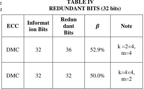
The issue is that DMC technique requires more redundant bits. The redundant bits of these protection codes are shown in Table IV, where a coding efficiency β is used
to evaluate the area overhead of memory cell.
β =Redundant bits/Redundant
bits + Information bits
If the value of β is small, the code needs
lower memory cell .From this table, we can see that Hamming code has the least β value but its
The scaling down of CMOS technology has resulted in a dramatic increase in the number of MCUs. In 90-nm technology, more than three errors have been observed in radiation test so Hamming, MC, and PDS are not good choices for protecting memory. The proposed scheme needs higher β value than other codes but it has higher
correction capability. Therefore, designers should choose the optimal combination of k and m based on the radiation test to provide a good tradeoff between reliability and redundant bits.
Fig. 9 CCCs of different protection codes.
We have also used a metric to assess the efficiency of DMC is compared to PDS, MC, and Hamming, which is called correction coverage per cost (CCC) and can be calculated as follow
CCC= Correction Coverage/cost
where Cost is obtained by
Cost = Area · Power · Delay · Redundant bits.
Fig.9 shows the values of this metric for different protection codes. From this figure.9, we can see that the scheme has a higher CCC value than other codes except that only one MCU occurs. Therefore, based on the results in Table III and Fig.9, the proposed scheme is quite suitable for high-speed memory applications. It should be mentioned that when the number of errors is more than two per word, Hamming and MC codes cannot correct any error.
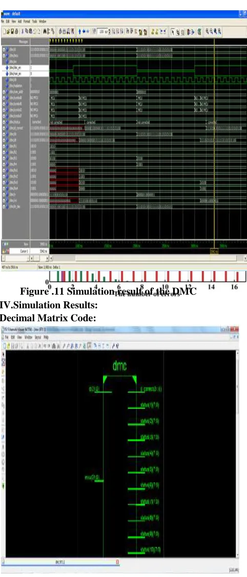
Figure .11 Simulation result of the DMC IV.Simulation Results:
Decimal Matrix Code:
Figure.10 Synthesis structure of decimal matrix code
Figure.12 Delay analysis of DMC technique
Timing Summary: --- Speed Grade: -7
Minimum period: 4.593ns (Maximum Frequency: 217.723MHz)
Minimum input arrival time before clock: 12.950ns
Maximum output required time after clock: 13.734ns
Maximum combinational path delay: 13.950ns.CONCLUSION
In this paper, novel per-word DMC was proposed to assure the reliability of memory. The proposed protection code utilized decimal algorithm to detect errors, so that more errors were detected and corrected. The obtained results showed that the proposed scheme has a superior protection level against large MCUs in memory The only drawback of the DMC is that more redundant bits are required to maintain the higher reliability of memory .The future work has been planned to reduce the redundancy bit by analyzing the parity matrix codes.
REFERENCES
[1] E.Ibe, H.Taniguchi, Y.Yahagi, K. Shimbo, and T.Toba, (Jul.2010) “Impact of scaling on neutron induced soft error in SRAMs from
an 250nm to a
22nmdesignrule,”IEEETrans.ElectronDevices ,vol.57,no.7,pp.1527 1538.
[2] A. Sanchez-Macian, P. Reviriego, and J. A. Maestro, “Hamming SEC-DAED and extended hamming SEC-DED-TAED codes through selective shortening and bit placement, ”IEEE Trans. Device Mater.
Rel.,to be published.
[3] S.Liu, P.Reviriego, and J.A.Maestro, (Jan.2012) “Efficient majority logic fault detection with difference- set codes for memory applications, ”IEEE Trans. Very
Large ScaleIntegr .(VLSI)
Syst.,vol.20,no.1,pp.148–156.
[4] M.Zhu, L.Y.Xiao, L.L.Song, Y.J.Zhang, and H.W.Luo, (Mar.2011) “New mix codes for multiple bit up sets mitigation in fault-secure memories,” Microelectron.J.,vol. 42, no.3 ,pp. 553–561.
[5] P.Reviriego, M.Flanagan, and J.A.Maestro,(Mar 2012) “A (64, 45) triple error correction code for memory applications, ”IEEE Trans. Device Mater.
Rel.,vol.12 ,no.1, pp.101– 106.
[6] S.Baeg, S. Wen, and R. Wong, (Apr.2010) “Minimizing soft errors in TCAM devices: A probabilistic approach to determining scrubbing intervals,” IEEE implemented with built in current sensors and parity codes for multiple bitup set correction, ”IEEETrans.Rel.,vol.60,no.3,pp.528– 537. strained-Si PMOS transistors on SRAM soft error rates,” IEEE Trans. Nucl. Sci., vol. 59, no. 4, pp. 845–850.
[10] C. A. Argyrides, P. Reviriego, D. K. Pradhan, and J. A. Maestro,(Aug. 2010) “Matrix- based codes for adjacent error correction,” IEEE Trans. Nucl. Sci., vol. 57, no. 4, pp. 2106–2111.
[11] S.Yasotha,V.Gopalakrishnan and M.Mohankumar,( June.2015) “Multi-sink Optimal Repositioning for Energy and Power Optimization in Wireless Sensor Networks”
in Wireless Personal Communications, Volume 82, Number 3.
[12] M.Mohankumar,V. Gopalakrishnan and S.Yasotha,( MAY 2015 )“A Vlsi Approach For Distortion Correction In Surveillance Camera Images,” in ARPN Journal of Engineering and Applied Sciences, VOL. 10, NO. 9,ISSN 1819-6608.
[13] M.Mohankumar,R.Gowrimanohari,( Oct 2014)“A Novel Design Of Current ModeMultiplier/Divider Circuits For Analog Signal Processing,” in International Journal of Computer Science and Mobile Computing, Vol. 3, Issue. 10, pg.918 – 925.
[14] M.Mohankumar, R.Gowrimanohari,(May 2015) “VLSI Architecture For Barrel Distortion Correction In Surveillance Camera Images,” In Journal of Electronics And Computer Sciecne, Vol 2, Issue 5, Paper 9,. [15] V.Pavithra,M.Mohankumar,(Feb.2014