Small-Size Broadband Coding Metasurface for RCS Reduction Based
on Particle Swarm Optimization Algorithm
Honggang Hao, Shimiao Du*, and Ting Zhang
Abstract—Radar cross section (RCS) reduction technology has great significance in stealth and other fields. A PSO-FSP algorithm is proposed based on the particle swarm optimization algorithm and the far-field scattering characteristics of coding metasurface to obtain the optimized coding sequence for RCS reduction. According to the principle of coding metamaterial, a 1 bit cell structure is designed. Therefore, a coding metasurface is constructed by arranging the unit cells based on the optimized coding sequence. Simulation results show that, in the case of vertical incidence, compared with metal plates of the same size, the metasurface can achieve more than 10 dB of RCS reduction within the broadband range from 15 GHz to 35 GHz, and the maximum reduction can reach 36 dB. The proposed coding metasurface has been successfully fabricated and measured, and there is a good agreement between simulated and measured results.
1. INTRODUCTION
In modern military affairs, low detectability is a crucial factor to enhance the survivability of weapons on the battlefield, so the development of RCS reduction technology is particularly important. There are two traditional ways to reduce RCS. One is shaping technology, but it is not suitable for the bistatic RCS reduction. The other one is coating absorbing materials, but the temperature will rise, which will increase the probability of detection by enemy infrared detection equipment [1]. In recent years, some new technologies such as metasurface have been used for RCS reduction [2–4]. In 2014, the National Key Laboratory of Millimeter Wave of Southeast University team firstly proposed the concept of “coding metasurface” which is composed by arranging metamaterial units with stable phase difference in a certain way [5]. RCS reduction is also an important research area of coding metasurface. As a new research field, coding metasurface provides a new way for RCS reduction. The key of coding metasurface design for RCS reduction is coding sequence, so intelligent optimization algorithms can be used to optimize coding sequence. For example, ergodic algorithm [6], simulated annealing algorithm [7], genetic algorithm [8–10], and particle swarm optimization algorithm [11–15] can optimize the coding sequence to achieve RCS reduction. There is room for further improvement in the bandwidth of RCS reduction.
In this paper, particle swarm optimization (PSO) algorithm combined with far-field scattering pattern (FPS) model is proposed to optimize the coding sequence. Then a new type of small-size broadband coding metasurface based on polarized rotating materials [16] and optimal coding sequence is designed, which can realize the reduction of broadband RCS and improve the maximum reduction.
Received 9 April 2019, Accepted 22 May 2019, Scheduled 24 May 2019
* Corresponding author: Shimiao Du ([email protected]).
2. OPTIMAL DESIGN OF CODING SEQUENCE
2.1. Far-Field Scattering Pattern Model of Coding Metasurface
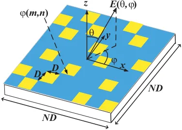
The design principle of coding metasurface can be analyzed by the theory of phased array antenna. Fig. 1 is a schematic diagram of coding metasurface. Suppose that the metasurface is composed of
N×N array elements with a period ofD. Each array element is composed of the basic unit structure of “0” or “1”, and the distribution of “0” and “1” on the surface is arbitrary. We assume that the reflection phase of the (m, n)th element is ϕ(m, n). According to the principle of 1 bit coding metasurface, it is easy to know that the phase value is 0 or 180 degrees. When the plane wave is incident vertically, the far-field scattering of the metasurface can be expressed as [5]:
f(θ, ϕ) =fe(θ, ϕ)
N
m=1
N
n=1 exp
−i
ϕ(m, n) +KDsinθ
m−1
2
cosϕ+
n−1
2
sinϕ
(1)
θandϕare the elevation angle and azimuth angle, respectively. fe(θϕ) is the scattering patterns of the array element. Then the directional coefficient of coding metasurface can be expressed as:
Dir(θ, ϕ) = 4π|f(θ, ϕ)| 2 2π
0
π/2
0
|f(θ, ϕ)|2sinθdθdϕ
(2)
Since the reflective phases of the basic elements “0” and “1” are 0 and 180 degrees, the scattering characteristics of the two elements can be canceled by each other. It can be seen from Formulas (1) and (2) that the proposal of coding metasurface provides a new idea for RCS reduction technology, which designs reflective coding metasurface. Because the coding metasurface is composed of different basic unit structures sorted by a certain coding sequence, we can make the electromagnetic wave irradiating on the coding metasurface scatter as many directions as possible into the space by designing coding sequence. According to the energy conservation law, the beam energy in each direction is low, so the RCS reduction can be achieved.
D D
z E(θ,ϕ)
y
x
θ
ϕ
ND
ND
ϕ(m,n)
Figure 1. Schematic diagram of coding metasurface principle.
2.2. PSO-FSP Algorithm
description of the position of the next generation of particles can be expressed as [15]:
vji =w∗vji +c1∗rand(0,1)∗
pbestij−xij+c2∗rand(0,1)∗
gbesti−xij (3)
where pbestij and gbesti represent the optimal position of individual particles and the global optimal position, respectively. The function rand(0,1) denotes a random number between 0 and 1. c1 and c2 are called learning factors or acceleration factors which are usually set to a value of 2. wmeans inertia weight, and the algorithm using the weight factor which changes with time is usually better than the fixed one. The commonly used mathematical expressions of weight factors are as follows:
w(k) =wmax−(wmax−wmin)k/Niter (4)
Niter is the maximum number of iteration. wmax and wmin are usually set to 0.9 and 0.4.
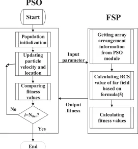
In order to obtain the best performance of coding metasurface, the PSO algorithm is combined with the Far-field Scattering Pattern (FSP) model of coding metasurface to optimize the coding sequence. The flow chart of PSO-FSP algorithm is shown in Fig. 2, in which two modules are used to optimize the phase arrangement of the metasurface. The PSO module evaluates the fitness in each iteration, updates the particle velocity and position, and then sends the information to the FSP module. With the help of MATLAB, we can complete the design of the algorithm. The position of the population particles, which is the coding sequence to be optimized, can be regarded as a random matrix containing only 0 and 1, and the speed can be set same. The fitness function can be set as:
f itness=f(θ, ϕ) (5)
Start
Population initialization
Updating particle velocity and
location
Comparing fitness values
i=Niter?
End Yes No
Getting array arrangement
information from PSO
module
PSO
Input parameter
Calculating RCS value of far field
based on formula(5)
Output fitness
Calculating fitness values
FSP
Figure 2. The flow chart of PSO-FSP algorithm.
The core of this flowchart is that the PSO module generates all kinds of phase arrangements of coding metasurface, and their performance will be judged through FSP module to find the best solution.
The population used in the PSO module is set to 100, and the number of iterations Niter is set to 500. The initial phase value of the unit cell structure is 0 or π, which is simplified to 0 or 1 in the design of the algorithm. The fitness function curve obtained by numerical optimization in MATLAB is shown in Fig. 3(a). It can be seen that the curve decreases rapidly in the initial stage and then tends to be a stable value. The final result of coding sequence optimization is shown in Fig. 3(b).
0 100 200 300 400 500
1 2 3 4 5 6 fitnes s Iteration 1 0 0 0 0 1 1 0 1 0 0 1 0 1 1 1 1 0 1 1 0 0 0 0 1 0 0 1 0 1 1 1 1 1 1 1 0 1 0 0 1 1 1 0 0 1 0 0 1 0 0 0 0 0 1 1 0 1 0 0 0 0 0 1 0 1 0 1 0 1 0 0 0 1 0 1 0 1 1 1 1 1 1 1 1 1 0 0 0 0 1 0 0 1 0 0 1 1 1 1 (a) (b)
Figure 3. (a) The fitness function curve. (b)Optimal coding sequence.
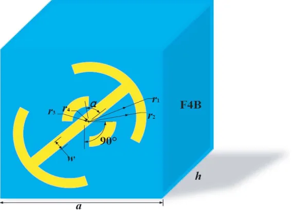
3. OPTIMIZED METASURFACE DESIGN 3.1. Unit Cell Design
The whole unit cell structure is composed of three layers as shown in Fig. 4. The middle layer is a dielectric layer, and the selected dielectric substrate is F4B with a relative permittivity of 2.65 and loss
tangent of 0.001. The top and bottom layers are metal layers with thickness of 0.018 mm. The width and thickness of the dielectric substrate have great effect on the design of the structure. After parameter optimization, the unit cell period is determined to be 3 mm; the thickness of dielectric layer is 1.5 mm; and the other structural parameters of unit cell are: α = 60◦,w= 0.2 mm, r1 = 1.3 mm, r2 = 1.1 mm,
r3 = 0.6 mm,r4= 0.4 mm.
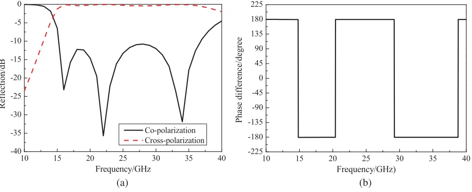
CST Microwave Studio software is used to study the phase and reflection characteristics of the unit cell structure. The results are shown in Figs. 5(a) and (b). As we can see from Fig. 5(a), the 10 dB polarization conversion bandwidth of “0” or “1” unit cell is 15–35 GHz under vertical incidence. Fig. 5(b) is the cross-polarized reflection phase difference between “0” and “1” elements. It can be seen from Fig. 5(b) that, ideally, 180-degree phase difference can be achieved in the whole broadband when
x-polarized wave is completely converted into y-polarized wave. Therefore, we can use these two cell structures to design coding metasurface through a certain coding sequence.
10 15 20 25 30 35 40
-40 -35 -30 -25 -20 -15 -10 -5 0
Reflection/dB
Frequency/GHz
Co-polarization Cross-polarization
10 15 20 25 30 35 40
-225 -180 -135 -90 -45 0 45 90 135 180 225
Phase difference/degree
Frequency/GHz)
(a) (b)
Figure 5. (a) Reflection characteristic curve. (b) Phase characteristic curve.
10 15 20 25 30 35 40
-40 -35 -30 -25 -20 -15 -10 -5 0
RCS Reduction/dB
Frequency/GHz x polarize
(a) (b)
3.2. Simulation and Analysis of Coding Metasurface
According to the optimal sequence, a coding metasurface can be constructed by combining the unit cell structures. The size of the coding metasurface is 120 mm×120 mm. There are 10×10 basic units. In order to prevent the coupling between unit cells, a 4×4 sub-array cell is used to construct the whole coding metasurface, as shown in Fig. 6(a).
As a comparison, full-wave simulation is also carried out for the same size metal plate. Fig. 6(b) shows the RCS reduction of the coding metasurface during the working frequency band. It can be seen that in the range from 15 GHz to 35 GHz, RCS reduction can be achieved more than 10 dB, and the maximum reduction can reach 36 dB.
-90 -60 -30 0 30 60 90
-25 -20 -15 -10 -5 0 5
Bi
static RCS/dB
Theta/degree
Metasurface PEC
-90 -60 -30 0 30 60 90
-40 -35 -30 -25 -20 -15 -10 -5 0 5 10 15
Bistatic RCS/dB
Theta/degree
Metasurface PEC
-90 -60 -30 0 30 60 90
-40 -30 -20 -10 0 10 20
Bistatic RCS/dB
Theta/degree
Metasurface PEC
-90 -60 -30 0 30 60 90
-40 -30 -20 -10 0 10 20
Bistatic RCS/dB
Theta/degree
Metasurface PEC
(a) (b)
(c) (d)
Figure 7. Bistatic RCS of coding metasurface and PEC inY OZ plane. (a) 10 GHz. (b) 20.5 GHz. (c) 29.5 GHz. (d) 40 GHz.
side lobes are, the more the energy of main lobe will be suppressed, thus the RCS reduction can be realized. From Fig. 7, it can be seen that the metal plate produces a strong main lobe at all frequency points, which is consistent with the theory. For the coding metasurface, at 10 GHz and 40 GHz, the metasurface hardly suppresses the main lobe energy; at 20.5 GHz and 29.5 GHz, the side lobe energy is enhanced and the main lobe energy obviously suppressed. In conclusion, it is proved that the coding metasurface has a strong RCS reduction ability in the broadband range.
4. MEASUREMENT AND DISCUSSION OF CODING METASURFACE
According to the optimal coding sequence given above, a coding metasurface template is fabricated. As shown in Fig. 8, the thickness of the whole object is 1.5 mm, and the width of the edge is 120 mm, so the overall size is 120 mm×120 mm×1.5 mm.
0
1
Figure 8. Physical map of coding metasurface.
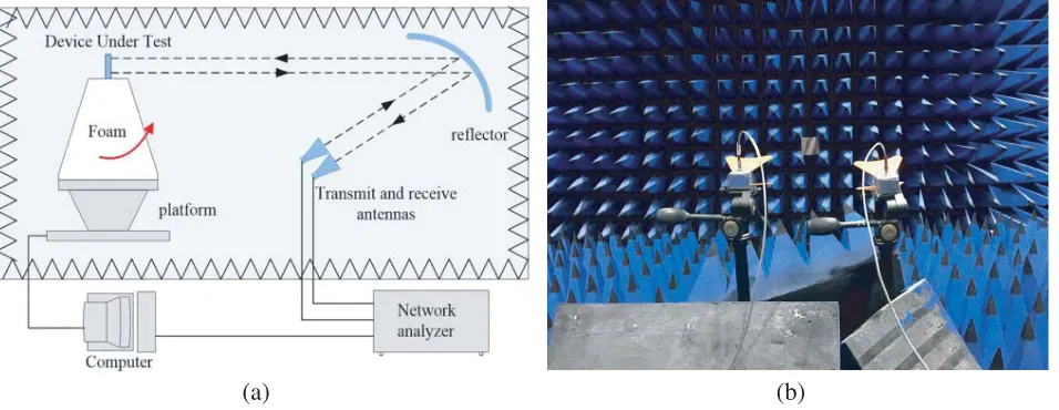
The testing method is free space method. The experimental equipment is a vector network analyzer (10 MHz∼50 GHz) and two horn antennas with working bands of 10 GHz∼40 GHz. The test platform is constructed by connecting two horn antennas to the input and output of the vector network analyzer, respectively, i.e., one horn antenna as the transmitting source and the other horn antenna as the receiver. We fixed the sample to be measured at the same level as the two horn antennas and then conducted the measurement. The test environment is shown in Fig. 9.
(a) (b)
10 15 20 25 30 35 40 -40
-35 -30 -25 -20 -15 -10 -5 0 5
RCS Reduction/dB
Frequency/GHz Simulation
-10dB line Measurement
Figure 10. Comparisons between measured results and simulation results.
Figure 10 shows a comparison between the measured RCS reduction characteristics and the simulation results of the coding metasurface irradiated by a vertical incident electromagnetic wave. In order to facilitate the analysis and comparison, a−10 dB line is added to the figure, so it can be clearly seen that the measured results are almost consistent with the simulation results, and the RCS reduction values in the broadband range from 15 GHz to 35 GHz are basically above 10 dB. Then the maximum RCS reduction of the measured results is −28 dB, which is lower than that of the simulation, and the measured RCS reduction curve has more burrs. The reasons for these problems may be as follows: (1) There are errors in the process of physical machining; (2) Environmental factors; (3) Although the simulation is carried out under the condition of vertical incidence, it is impossible for the horn antenna to be completely perpendicular to the metasurface to be measured, or even to be on the same horizontal plane in the process of building the platform, thus affecting the test results. However, in general, the test results have reached an ideal state and maintained a good RCS reduction capability in broadband.
Table 1. Comparison of this work with references. RSCR: Rcs Rduction. BW: Bandwith.
Article RCSR (dB) Size (mm2) BW (GHz) Max RCSR (dB)
This work 10 120×120 15–35 28
Reference [8] 10 216×216 17–42 24
Reference [9] 10 240×180 5.21–15.09 32.5
Reference [11] 10 210×210 7.3–10.8 19.15
Reference [15] 10 286×286 15.6–36.5 16.7
5. CONCLUSION
ACKNOWLEDGMENT
This work was financially supported by the Natural Science Foundation of Chongqing (No. cstc2018jcyjAX0508) and by the Science and Technology Research Program of Chongqing Mu-nicipal Education Commission (Grant No. KJQN201800639).
REFERENCES
1. Knott, E. F., J. Shaeffer, and M. Tuley, Radar Cross Section, Sci. Tech. Publishing, 2004.
2. Chen, J., Q. Cheng, J. Zhao, D. S. Dong, and T.-J. Cui, “Reduction of radar cross section based on a metasurface,” Progress In Electromagnetics Research, Vol. 146, 71–76, 2014.
3. Chen, C., Z. Li, L. Liu, J. Xu, P. Ning, B. Xu, X. Chen, and C. Q. Gu, “A circularly-polarized metasurfaced dipole antenna with wide axial-ratio beamwidth and RCS reduction functions,” Progress In Electromagnetics Research, Vol. 154, 79–85, 2015.
4. Jiang, W., Y. Xue, and S.-X. Gong, “Polarization conversion metasurface for broadband radar cross section reduction,”Progress In Electromagnetics Research Letters, Vol. 62, 9–15, 2016. 5. Cui, T. J., M. Q. Qi, X. Wan, et al., “Coding metamaterials, digital metamaterials and
programmable metamaterials,” Light Science & Applications, Vol. 3, No. 10, e2181-9, 2014. 6. Xiao, L., J. Gao, L. Xu, et al., “A coding diffuse metasurface for RCS reduction,” IEEE Antennas
& Wireless Propagation Letters, Vol. 16, 724–727, 2017.
7. Zhao, Y., X. Cao, J. Gao, et al., “Broadband diffusion metasurface based on a single anisotropic element and optimized by the Simulated Annealing algorithm,”Scientific Reports, Vol. 6, 238961–9, 2016.
8. Sun, H., C. Gu, X. Chen, et al., “Broadband and broad-angle polarization-independent metasurface for radar cross section reduction,”Scientific Reports, Vol. 7, 407821–9, 2017.
9. Si, J. L., Y. C. Xiang, M. X. Li, et al., “Ultra-broadband reflective metamaterial with RCS reduction based on polarization convertor, information entropy theory and genetic optimization algorithm,” Scientific Reports, Vol. 5, 374091–12, 2016.
10. Sui, S., H. Ma, J. Wang, et al., “Absorptive coding metasurface for further radar cross section reduction,”Journal of Physics D: Applied Physics, Vol. 51, No. 6, 0656031–6, 2017.
11. Zhou, Y., X. Y. Cao, J. Gao, et al., “RCS reduction for grazing incidence based on coding metasurface,”Electronics Letters, Vol. 53, No. 20, 1381–1383, 2017.
12. Wang, K., J. Zhao, Q. Cheng, et al., “Broadband and broad-angle low-scattering metasurface based on hybrid optimization algorithm,”Scientific Reports, Vol. 4, No. 4, 59351–6, 2014.
13. Su, J., Y. Lu, H. Zhang, et al., “Ultra-wideband, wide angle and polarization-insensitive specular reflection reduction by metasurface based on parameter-adjustable meta-atoms,”Scientific Reports, Vol. 7, 422831–11, 2017.
14. Su, J., H. He, Z. Li, et al., “Uneven-layered coding metamaterial tile for ultra-wideband RCS reduction and diffuse scattering,”Scientific Reports, Vol. 8, No. 1, 81821–9, 2018.
15. Su, J., Y. Lu, Z. Zheng, et al., “Fast analysis and optimal design of metasurface for wideband monostatic and multistatic radar stealth,”Journal of Applied Physics, Vol. 120, No. 20, 2051071– 11, 2016.
16. Gao, X., X. Han, W. P. Cao, et al., “Ultra-wideband and high-efficiency linear polarization converter based on double V-shaped metasurfaces,” IEEE Transactions on Antennas & Propagation, Vol. 63, No. 8, 3522–3530, 2015.