www.ijiset.com
78
Hardness Analysis of Ti-6Al 2Sn 4Zr 6Mo using Vickers and
Micro Vickers Indentation Tests.
Muhammad Irfan KhanP 1,*
P
, Abdul ShakoorP 1
P
, Riaz MuhammadP 2
P
, Muhammad UsmanP 3
P
, Numan KhanP 1
P
1
P
Department of Mechanical Engineering, University of Engineering and Technology Peshawar, Pakistan.
P
2
P
Department of Mechanical Engineering, CECOS University of IT & Emerging Sciences Peshawar, Pakistan.
P
3
P
Assistant Engineer (Corrosion), OGDCL, Pakistan *Corresponding Author: email: [email protected]
Abstract
Titanium and its alloys over the past few decades are
becoming the preferred choice over other materials in
a lot of engineering applications. This trend is driven
by the balanced set of mechanical properties that
these alloys exhibit like a high resistance to
corrosion, high specific strength to name a couple.
New alloys of Titanium are produced which need to
be studied from differect perspectives. In this work
both Vickers and Micro Vickers indentation
techniques were used to evaluate hardness of recently
developed alloy Ti-6246. To check the response of
the material for any piles-up or sinks-in at the
indents, light microscopy images were taken. They
are also presented in this work. Further the effects of
the projected area, indentation depth and indentation
load on hardness values are also presented
graphically.It was found that the hardness values
obtained through both the techniques were in close
agreement with each other and also with those
reported in literature for Berkovich indenter. Also
light microscopy images are obtained which show no
crack initiations or piles-up at the boundary of the
indents.
Keywords: Micro Vickers Indentation; Hardness; Contact; Area; Penetration depth; Light Microscopy.
1 Introduction
The objective of engineering techniques is to get the
durable outcome at the lowest cost. For this reason
extensive research has been done in developing the
methods for enhancing the properties of already
existing materials and to produce new materials in
form of composites and alloys that will best fit the
cause. Titanium (Ti) is one such metal that has
gained a lot of attention of the material engineers. In
the last couple of decades Ti has gained great
importance in engineering sciences and has attracted
a lot of market demand for numerous engineering
applications for two reasons, one Ti has excellent
mechanical properties ranging from good formability
to the ability to put up with extreme temperature
conditions and from high specific strength to
excellent corrosion resistance and the second reason
is that unrelenting research work has been done on Ti
to develop new alloys of it with even better
mechanical properties to meet the requirements of
critical performance related applications [1]. Ti and
its alloys have a vast scope of industrial applications.
This scope of application spans over many sectors
like marine, offshore oil and gas plants, chemical,
www.ijiset.com
79
many more [1]. The high melting point of around1675 P 0
P
C of Ti puts it in the position of most favorite
choice for application in turbine engines [2]. The
high specific strength of titanium and its alloys make
it the perfect choice for the aircraft industry. The use
of titanium in different version of Boeing Aerospace
Company’s aircrafts was around 15 million pounds.
Now it is estimated that 20% of the basic structural
components of the new 787 dream liner are going to
be made of titanium alloys. The cost of the extraction
of raw material, processing, production and
manufacturing of titanium alloys remain on the
higher side, but the most favorable set of properties
that it exhibits compensate for all that extra cost. As
the result of the research in the field of alloys
development of titanium recently a new alloy
Ti-6Al 2Sn 4Zr 6Mo (Ti-6246) has been developed.
Ti-6246 is seen as a replacement of Ti-6Al 4V
(Ti-64) the work horse alloy of titanium. Ti-6246 has
many advantages over Ti-64 for instance Ti-6246 can
be heat treated to higher strength and produced in
larger sections. Moreover the 6 % Molybdenum
contents of Ti-6246 make it corrosion resistant in
reducing environment, making it a better choice for
offshore oil and gas applications [3].
As Ti-6246 is a relatively new alloy, therefore, its
behavior and properties are studied at different levels.
Therefore, in this work Vickers hardness technique is
used to find the hardness of Ti-6246. As hardness
relates to the property of a material to resists plastic
deformation mainly because of penetration further it
can also be attributed to the ability to oppose
bending, abrasion, cutting and scratching [4]. Hence
hardness becomes one of the very important
mechanical properties to check for engineering
applications. On the other hand Vickers hardness
tests were developed by Smith and Sandland in 1925
in UK to overcome the shortcomings of the
traditional Brinell hardness test[5].
There are two types of Vickers hardness test in
practice. This classification is based upon the nature
of the testing and its objectives. The two types are
Macro and Micro Vickers indentation.
Since 1900 Brinell test has been widely used to
calculate the hardness of various materials mainly as
rolled, as cast and annealed metals. In these cases the
alloys are inhomogeneous. A large indenter of 10mm
diameter is used in Brinell hardness tests, this
averages out the inhomogenieties to obtain bulk
hardness values. In contrast the macro Vickers
indenter creates a smaller impression therefore the
inhomogenieties present in the material are not
averaged out as well as the Brinell test [6].
Nonetheless it is found that with the increment in test
load and the consequent increase in the indent size
the macro Vickers indentation tests yields fairly
consistent hardness numbers. Macro Vickers
indentation can be successfully applied to heat treated
steels and cold-rolled metals.
By comparison micro Vickers indentation are done at
low loads. It is used to assess the hardness variation
whether intentionally or unintentional induced. Micro
Vickers indentation also proves to be precise tool to
characterize segregation and banding [6]. This helps
in indentifying constituents and characterization of
microstructure gradients. In other words we can say
that macro Vickers tests are used to find gross
product average but if one is interested in hardness
gradient of the material then micro Vickers is the
option. Another distinguishing feature between the
two technique is that macro Vickers are performed at
shop floor to find the bulk average hardness while
micro Vickers test are performed in laboratories [5].
In the proceeding lines the procedure followed in
www.ijiset.com
80
obtained are presented and discussed. Further theeffects of parameters like penetration depth, contact
area and diagonal size on hardness number are
presented graphically.
2 Material and Methodology
2.1 Material
The material used in this work is standard Ti-6246
alloy, obtained from Gfe-Metalle and Materialien
GmbH situated in Nuremberg, Germany. 2× Vacuum
arc remelting procedure was used in the production
of the subject alloy. Forging process was used to
decrease the diameter of the rod from 200mm to
50mm in the two phase field followed by air cooling,
stress-relief annealing and stripping [7].
2.2 Methodology
In total four samples were prepared which were cut
from a round bar of Ti-6246. Each sample had a
diameter of 45 mm & thickness of 6mm. To remove
the roughness introduced by the sectioning, grinding
of finer and finer abrasives was applied in sequences.
Grit sequence of 120, 240, 320, 400, 600 mesh was
applied in steps for 3 to 6 minutes. Between each
steps the specimen was rinsed to remove the previous
grinding media. Polishing wheels of eight inch
diameter and speed range of 200-600 rpm was used.
To keep the heat generated and the metal entrapment
between particles at minimum wet grinding was
applied. The indentation tests performed along with
the facilities are tabulated in Table 1.
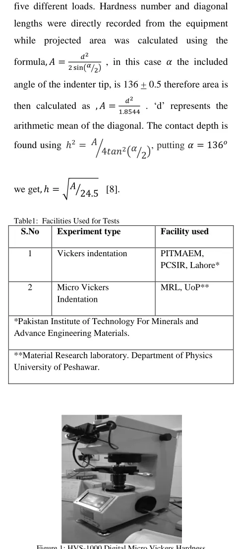
The micro Vickers indentation tests were performed
using HVS-1000 Digital Micro Vickers Hardness
testing equipment. Experiments were carried out at
five different loads. Hardness number and diagonal
lengths were directly recorded from the equipment
while projected area was calculated using the
formula,𝐴= 𝑑2
2 sin�𝛼 2� � , in this case 𝛼 the included
angle of the indenter tip, is 136 + 0.5 therefore area is
then calculated as ,𝐴= 𝑑2
1.8544 . ‘d’ represents the
arithmetic mean of the diagonal. The contact depth is
found using ℎ2= 𝐴
4𝑡𝑎𝑛2�𝛼
2
� �
� , putting 𝛼= 136𝑜
we get,ℎ=�𝐴�24.5 [8].
Table1: Facilities Used for Tests
S.No Experiment type Facility used
1 Vickers indentation PITMAEM, PCSIR, Lahore* 2 Micro Vickers
Indentation
MRL, UoP**
*Pakistan Institute of Technology For Minerals and Advance Engineering Materials.
**Material Research laboratory. Department of Physics University of Peshawar.
Figure 1: HVS-1000 Digital Micro Vickers Hardness
The Vickers tests were performed at PITMAEM of
PCSIR laboratories complex Lahore. The indentation
loads used were higher as compared to those used in
www.ijiset.com
81
images of the indents were obtained to check for anypiles-up or sink-in in the material.
3 Results and Discussion
The results obtained in micro Vickers indentation are
tabulated in Table-2
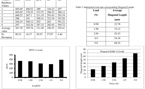
Table 2: Micro Vickers Hardness Tests Results
Loads(N) Vickers
Hardness Values
0.98 1.96 2.94 4.9 9.8
1 465.69 460.52 288 344.23 297 2 465.69 378.22 333.75 286.53 386.13 3 460.52 367.1 311.19 291.63 393.19 4 288 341 309.31 323.34 355.56 5 344.23 369.12 292 263 391.21 6 297 342.54 297.33 282.92 395.72 Average
value
367.78 359.76 311.40 296.35 392.61 St.
Deviation
90.22 16.37 20.52 27.07 4.46
Figure 2: Results of Micro Vickers Indentation
To comprehend the data in a more effective way its
plot is presented in Fig-2. It can be seen from Fig-2
that HVN number shows decrease in values as the
load increases. Though at 9.8N load increase is
recorded in the HVN number.
The relation of the load with the diagonal length is
shown in the figure 3.
Variation in hardness values is observed, one reason
to this situation is that as the load is increased it
results in more penetration and an increase in contact
depth and projected area is recorded. As discussed
earlier hardness values depend on the contact depth
and projected area therefore the results obtain here
show dependence of hardness values on the
indentation load [9].
Table 3: Indentation load and corresponding Diagonal Length.
Load
(N)
Average
Diagonal Length (μm)
0.98 22.78 1.96 32.12 2.94 42.43 4.9 54.18 9.8 68.54
Figure 3: Effect of Indentation load on diagonal length
It can be seen in the figure above that with the
increase in the applied indentation load the diagonal
length of the indent increases. This is an obvious
effect of increase in load. The diagonal length can be
viewed in the light microscopy images provided later
in this text.
As projected area is directly proportional to the
square of the diagonal therefore as the diagonal
length increases the projected area also increases.
The effects of increasing load on projected area are
0 100 200 300 400 500
0.98 1.96 2.94 4.9 9.8
HVN
Load(N) HVN vs Load
0 10 20 30 40 50 60 70 80
0.98 1.96 2.94 4.9 9.8
D
ia
g
on
al
l
en
gt
h
(
μm)
www.ijiset.com
82
similar to those on diagonal length and are presentedin figure 4.
Table 4: Indentation load and projected area
Load
(N)
Average
Projected area
(μmP
2
P
)
0.98 22.78 1.96 32.12 2.94 42.43 4.9 54.18 9.8 68.54
Figure 4: Effect of Indentation load on projected area
Contact depth is another important parameter to study
for indentation tests. The penetration indenter made
in Ti-6246 at different loads is presented in Fig 5.
Again it can be seen that the contact depth increases
as the indentation load increases. In other words
indenter penetrates more at higher loads.
Table 5: Indentation load and Contact depth
Load (N) Contact depth
(μm)
0.98 3.38 1.96 4.76 2.94 6.29 4.9 8.04 9.8 10.17
Figure 5: Effect of Indentation load on contact depth
Vickers indentation results are tabulated in Table 6 and the results are plotted in figure 6.
Table 6: Indentation load and Contact depth
Load (N) HVN (avg)
49 342.74 196 342.11 294 346.69 490 344.82
The overall average of the micro Vickers indentation
is HVN 292.92 while the overall average of Vickers
indentation is found to be HVN 344. The difference
is around 15% and this is due to the fact that micro
Vickers indentation gives us more localized output
while Vickers indentation gives us gross product
averaged value as larger area is entrapped under the
larger indenter tip.
Figure 6: Vickers Hardness test results
0 500 1000 1500 2000 2500 3000
0.98 1.96 2.94 4.9 9.8
P
ro
jec
ted
A
rea
(
μm
^
2
)
Load (N)
Projected Area vs Load
0 2 4 6 8 10 12
0.98 1.96 2.94 4.90 9.8
C
o
n
ta
ct
d
ep
th
(
μm)
Load (N) Contact Depth vs Load
338 340 342 344 346 348 350
49N 196N 294N 490N
H
VN
www.ijiset.com
83
Light microscopy images are obtained usingOlympus PMG -3 coupled with Charged Coupled
Device (CCD) with a DP-12 digital Camera shown in
figure 7.
Figure 7: Olympus PGM-3
The purpose of these images was to check the
response of Ti-6246 to indentation. To see whether
any piles-up or sink-in are found along the indent
boundaries.
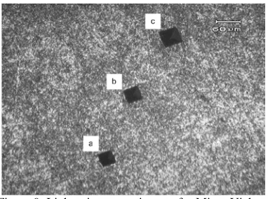
Figure 8 shows the images of Vickers indentation
while the light microscopy images of Micro Vickers
indentation are presented in figure 9.
Figure 8: Light microscopy images for Vickers indentation (a) 49 N (b) 194 N (c) 294 N (d) 490 N
Figure 9: Light microscopy images for Micro Vickers indentation (a) 2.94 N (b) 4.9 N (c) 9.8 N
Examination of images of figure 9 shows no
significant evidence of pile-ups.
4 Conclusion and Future Work
The main objective of this work was to analyze the
hardness of Ti-6246 with both Vickers and micro
Vickers indentation tests. Further with the help of
light microscopy the response of the material to
indentation was checked. It was concluded that the
hardness values obtained for both types of test fall
well within the range of hardness values reported for
the subject alloy in literature for different types of
indents. Moreover the hardness values obtained using
Vickers indentation were slightly greater than those
obtained for micro Vickers indentation because
Vickers indents provide averaged hardness value.
Further the diagonal length, projected area and
contact depth all are related in direct proportion to
indentation loads. If the load is increased all these
parameters will experience as an increase.
Examination of some light microscopy images hint
towards potential piles-up in the future with the help
of Atomic Force Microscopy these piles-up will
checked and quantified. Also, this data obtained can
be used to find the fracture toughness of Ti-6246. In
www.ijiset.com
84
check its effectiveness in the characterization of thesubject alloy.
References:
1. Peters, M., Leyens, C., 2003, “Titanium and titanium alloys, fundamentals and applications” , WILEY-VCH Verlag GmbH & Co.KGaA, Weinheim
2. Novotny, P.M., and Maurer, G. E., 2007, “Ultra high strength steel v/s Titanium alloys, Advanced Materials & Processes”, Vol.165, Issue.11, pp 37 – 40.
3. Titanium Engineers limited, Titanium 6246 Data Sheet, Sugar Land, Texas, USA, www.titaniumengineers.com,
http://www.titaniumengineers.com/uploads/ 1/7/9/5/17957627/6246_datasheet_white_us _1_new_logo.pdf , Accessed September 5, 2014.
4. Fischer-Cripps, A.C., & Mustafaev, I., 2000, “Introduction to contact mechanics”, New York: Springer.
5. Voort, G.F., Fowler .R., 2012 “Low-Load Vickers Microindentation”, Advance Material and Processes, Vol 12, pp 28-33. 6. Voort, G.F., 1989, “Results of an ASTM E-4
Round-Robin on the Precision and Bias of Measurements of Microindentation Hardness Impressions, Factors that Affect the Precision of Mechanical Tests”, ASTM STP 1025, ASTM, Philadelphia, p 3-39. 7. Muhammad, R., Hussain, M.S., Maurotto,
A., Siemersb, C., Roy, A., Silberschmid,V.V., 2013, “Analysis of a Free Machining α + β Titanium Alloy Using Conventional & Ultrasonically Assisted Turning” , Journal of Materials Processing Technology, Vol. 214, pp 906– 915.
8. Roy M., 2010, “Vickers Hardness
Measurements: Practices and Calibration Check”, Internal technical Bulletin, The University of British Columbia, Department of Materials Engineering, Vancouver, B.C., Canada.
9. Sahin O., 2007, “Indentation Load Effect on Young's Modulus and Hardness of Porous Sialon Ceramic by Depth Sensing Indentation Tests”, Chinese Physics Letters, Vol 24, Number 11.
10. Donachie, M.J.Jr., 2000, “Titanium, A technical guide”2nd ed., Ohio: ASM International.
11. Froes, F.H. (Sam)., 2004, “Titanium Alloys”, The hand book of advanced material: Enabling new designs, 1st ed., J.K. Wessel, Ed. New Jersey: John Wiley and Sons, pp.271-320.
12. Oliver, W.C., & Pharr, G.M., 1992, “An improved technique for determining hardness and elastic modulus using load and displacement sensing indentation experiments”, Journal of Materials Research, Vol. 7, pp.1564-1583.