ANALYSIS OF DISTRIBUTION
NETWORKS WITH
NON-CONVENTIONAL ENERGY
SOURCES
G o p a R a n j an Mohapatra
B.E. (Electrical)
A thesis submitted in fulfilment of the requirements for the degree of Master of Engineering
Department of Electrical and Electronic Engineering
Faculty of Engineering and Science
Victoria University of Technology
Australia
T h e impact of renewable energy installations connected to the utility grid is an impor-tant issue concerning the technical and economic viability of harnessing these emerg-ing energy sources. Distribution networks must be carefully controlled in order to maintain an acceptable power supply quality. T h e major sources of non-conventional energy are small scale generation and storage from mini hydro, photovoltaic, wind power, fuel cells, battery, flywheel, p u m p storage and biomass.
in-ternal buses of the generators. T h e reduced network, machine and exciter data are then combined to form a linearised state-space model representing the entire system.
The simulation studies are applied to a four machine ten bus system. It is clear from the analysis that m u c h care should be taken based on the stability point of view while
I declare that, to the best of m y knowledge, the research described herein is the result of m y o w n work, except where otherwise stated in the text. It is submitted in fulfilment of the candidature for the degree of Masters by Research in Engineering of Victoria University of Technology, Australia. N o part of it has already been
submitted for any degree nor is being submitted for any other degree.
G o p a Ranjan Mohapatra
I am most grateful to my supervisor, Prof. Akhtar Kalam, acting Head of the Department w h o has guided m e through this work. I a m indebted to him for his unceasing encouragement, support and advice. I wish to thank m y co-supervisor Dr.A. Z a y e g h , Assoc. Prof. Wally Evans, the ex-Head of Department, Assoc. Prof.
Patrick Leung, Associate Dean of Faculty of Science and Engineering for their
support during this research.
Many thanks should also go to my fellow research students in the department of Electrical and Electronic Engineering with w h o m I had m a n y helpful discussions throughout the last two years. The memories I shared with Mehrdad, O m a r , Iqbal, Mahabir, Rushan, Zahidul, Ravi, Sisira, Micheal Selesnew, Micheal H o a n g and
Ying will always be in m y mind. M y special thanks to Reza, Nasser, M a h m o o d and
N a v a for their help throughout this work.
I would like to express my sincere gratitude to Citypower Ltd., for their kind permission to use the Brunswick Energy Park. I would like to thank M r . Peter Zswack, Manager, Renewable Energy Products for his help. I a m very thankful to
the people w h o have helped m e directly or indirectly during the course of study.
Finally, I would like to express my thanks to all staff members in the Department of Electrical and Electronic Engineering for their help and assistance.
Last but by no means least, my mother (Rukmani Mohapatra), father
(Jagabandhu Mohapatra) should be recognized for their everlasting
AGC
BMS
CAA
COP
CPI
DVR
DSG
EPA
EPRI
FACTS
FERC
FUA
GTO
IEEE
MOS
NAAQS
NEAC
NEPA
NGPA
NSPS
PSD
PSS
PURPA
QF
S A G A S C O S E C
S M E S
Automatic Generation Control Battery Management System Clean Air Act
Current Operational Problems C o m m o n Price Index
Dynamic Voltage Regulator
Dispersed Storage and Generation Environmental Protection Agency Electric Power Research Institute Flexible A C Transmission System Federal Energy Regulator Commission Fuel Use Act
Gate-turn-off thyristor
Institute of Electrical and Electronic Engineers Metal Oxide Semi-conductor
National Ambient Air Quality Standards National Energy Advisory Committee National Environment Policy Act Natural Gas Policy Act
N e w Source Performance Standards Prevention of Significant Deterioration Power System Stabiliser
Public Utility Regulatory Policies Act Qualifying Facilities
South Australia Gas Company State Electricity Commission
28. S T A T C O N Static Condenser
29. S V C Static Var Compensator 30. S V S Static Var System
x State Vector of the system
Xj State Variable of the system
n no.of inputs to the system
u Column vector of input to the system
x derivative of the state variable x
y column vector of outputs
g vector relating input variables to output variables
A small deviation
X eigen values of A
§ eigen vectors of A
vi/. left eigen vector
Cj non zero constant
6 Perturbation constant
n dependant variable
t time
N turn winding
Rw total resistance in o h m s
Rn Reluctance
Sm non linear hysteresis parameter
fm(f) non-linear function of flux
f J —) rate of change of flux s
dt
L non linear inductance
R non linear resistance
ix Primary current in transformer
i2 Secondary current in transformer
tan( 8 ) capacitor loss angle
fe(q) non linear capacitance as a function of charge
fc(q') non linear conductance as a function of rate of change charge
p(t) electronic polarisation
vR Voltage regulator output
v
Rmax maximum voltage regulator output
v
Rmin minimum voltage regulator output
Efd machine field voltage
YN network node admittance matrix
OXL overexcitation limiter
Ifd direct axis field current
ILrM over excitation limiter current
Cc Coupling Capacitance
ST3 Statis rectifier
Aw rotor angular velocity
A8 rotor angular displacement
b frequency of oscillation
time constant
a
SVSs Static Var Systems
x_l leakage reactance
r_a resistance
x_d d-axis sychronous reactance
x'_d d-axis transient reactance
x"_d d-axis subtransient reactance
T'_do d-axis open-circuit time constant
T"_do d-axis open-circuit subtransient time constant
x_q q-axis sychronous reactance
x'_q q-axis transient reactance
x"_q q-axis subtransient reactance
T'_qo q-axis open-circuit time constant
T"_qo q-axis open circuit subtransient time constant
H inertia constant
d_o damping coefficient
The research that leads to this thesis has also resulted in the following conference paper publications.
[1] G. Ranjan Mohapatra, A.Kalam, A.Zayegh, R.J.Coulter, "Dynamic modelling of DistributionNetwork with Non-conventional Energy Sources", Australiasia Power Engineering Conference (AUPEC-96). October 22 - 24, Melbourne University, Melbourne.
[2] G. Ranjan Mohapatra, A.Kalam, A.Zayegh, RJ.Coulter, "Issues of concern in a Distribution Network with non-conventional energy sources", University Power
Engineering Conference (UPEC-96). September 22 - 24, Greece.
[3] R. Nayak, G. Ranjan Mohapatra, A.Kalam, A.Zayegh, "Modern concept of Boiler Management", Australiasia Power Engineering Conference (AUPEC-96). October
22 - 24, Melbourne University, Melbourne.
[4] G. Ranjan Mohapatra, A.Kalam, A.Zayegh, RJ.Coulter, "Voltage Stability Study of Distribution network with Non-conventional Energy sources", Third International
Abstract i
Declaration iii Acknowledgement iv
List of Abbreviation v Nomenclature vii Publication xi
1 Introduction and Review 1
1.1 Introduction 1
1.2 Dispersed Storage Generation 3
1.2.1 Introduction 3 1.2.2 Cogeneration in United States of America 6
1.3 Cogeneration in Australia[10] 10 1.3.1 Cogeneration data 11 1.3.2 Victorian support ••• 11
1.3.3 S E C Support for cogeneration 14 1.4 Integration of Dispersed Storage Generation 19
1.4.1 Operational Problems 21 1.5 Power Electronic Controllers 26
1.6 Storage Batteries 27 1.7 Further Reviews 30 1.8 Scope and Objective 32 1.9 Originality of Thesis 33 1.10 Development of Thesis 34
2 Mathematical Modelling 36
2.1 Introduction 36
2.1.1 State-Space Representation 37 2.1.2 EigenProperties of the State Matrix 46
2.2 Numerical Integration Methods 4 9
2.2.1 Euler Method 5 0
2.3 Component Modelling 5 2
2.3.1 Modelling T h e Inductor 5 3
2.3.2 Modelling The Transformer 5 5
2.4 Modelling The Capacitor 56
2.5 Synchronous Machine Modelling 5 7
2.6 Modelling of Excitation Systems 61
2.6.1 Type D C 1 exciter model 62
2.7 Conclusion 65
3 Transient Stability 66
3.1 Introduction 66
3.1.1 Small-signal (or small-disturbance) stability 67
3.2 Small System Stability of a single machine infinite bus system 69
3.2.1 The Power System Model 71
3.2.2 Dynamic Stability Analysis 71
3.2.3 System Investigated 72
3.3 Small Signal Stability of a four machine ten bus system 76
3.3.1 The Power System Model 76
3.3.2 System Investigated 76
3.4 Factors influencing transient stability: 82
3.5 Methods of improving stability 83
3.5.1 Transient Enhancement Stability 84
3.6 Conclusion ...87
4 Voltage Control and Stability 88
4.1 Introduction
884.2 Voltage Stability Analysis
9 14.3 Modelling Requirements
9 24.4 Dynamic Analysis • 93
4.5 System Investigated - 95
4.6 Results: The figures below shows the phase profile, voltage profile and
ma-chine reactive power for increase in power by ratio of 1,1.5 and 2 98
4.6.1 Analysis of the results H3
4.7 Prevention O f Voltage Collapse 113
4.7.1 System Design Measures H3
4.7.2 System-Operating Measures
1 1 64.8 Conclusion
1 1 75 Private Generation- Control, Connection and Operational
Issue
1 1 911C
5.1 Introduction
5.1.1 Delivery System Characteristics
llL5.2.1 Control and regulation of voltage and frequency under normal system
operating condition 126
5.2.2 Operating in island m o d e 127 5.2.3 Risk of energising a dead utility/cogenerator inter-tie circuit from the
cogenerator's side 128
5.2.4 Having an unbalanced three phase load to be supplied by a
cogenera-tor during export period 128
5.2.5 Unstable condition on acogenerator following delayed clearance of a
fault on the utility system 129
5.3 Regulatory and contract issues [67][68] 129
5.3.1 Introduction 129 5.3.2 General Requirements 130
5.3.3 Requirements for Parallel Operation 131
5.3.4 Technical Aspects 132 5.3.5 Quality of Supply 135
5.3.6 Operation 136 5.3.7 Operation with Alternative Connection to the Utility System 137
5.4 Conclusion 139
6 Private Generation - Protection and Control 140
6.1 Introduction 140
6.2 Protection Requirements 141 6.2.1 Dispersed Generating Plant 141
6.2.2 Interconnecting system 142
6.2.3 Utility Network 143 6.2.4 Protection Co-ordination 143
6.3 Present State of the Art 144 6.3.1 Protection and Control - integrated Approach 145
6.3.2 Design of an automatic control system 148
6.4 Conclusion 150
7 Conclusion
l527.1 Introduction 152
7.2 Transient Stability 1 5 2 7.3 Voltage Stability 1 5 3 7.4 Ratings of Protective Devices 154
7.5 Advantages 1 5 5 7.5.1 Transmission Grid Benefits 156
7.5.2 Generating Organisation Benefits 156
7.7 Future work: 158 7.8 Conclusion 161
7.8 References .163
Appendix A 170
Figure. 2.1. A distribution network connected with a cogenerator 37
Figure. 2.2. Euler Principle 51
Figure. 2.3. Field point on the hysteresis 5 3
Figure. 2.4. (a) Nonlinear Relucatance 5 4
Figure. 2.5. Circuit of Inductor 55
Figure. 2.6. High frequency model of the transformer 56
Figure. 2.7. Model of Capacitor 5 7
Figure. 2.8. Synchronous Generator Block Diagram (macjra) 59
Figure. 2.9. Synchronous Generator Field Saturation characteristics 6 0
Figure. 2.10.Exciter model D C 1 block diagram 64
Figure. 3.1. Single Machine connected to a large system through transmission lines 70
Figure. 3.2. Schematic Representation of single machine infinite bus 7 4
Figure. 3.3. 1 0 % perturbation 7 4
Figure. 3.4. 1 5 % perturbation 75
Figure. 3.5. 2 0 % perturbation 75
Figure. 3.6. 1 % perturbation 79
Figure. 3.7. 1 0 % perturbation 80
Figure. 3.8. 1 5 % perturbation 80
Figure. 3.9. 2 0 % perturbation 81
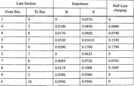
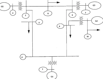
Figure. 3.10.Schematic representation of Four machine ten bus system 81
Figure. 4.1. V - Q Sensitivity for the bus 90
Figure. 4.2. Schematic representation of four machine ten bus system for Voltage Stability
study 9 7
Figure. 4.3. (a) Bus voltage phase profile 98
Figure. 4.4. (a) Bus voltage magnitude profile 98
Figure. 4.5. (a) machine reactive power 99
Figure. 4.6. (b) bus voltage magnitude profile 103
Figure. 4.7. (b) bus voltage phase profile 103
Figure. 4.8. (b)machine reactive power 104
Figure. 4.9. (c) bus voltage magnitude profile 108
Figure. 4.10.(c) bus voltage phase profile 108
Figure. 4.11.(c) machine reactive power 109
Figure. 7.1. A distribution network utilising variety of controllers 159
Table 1.1 Cogeneration Data 1 2
Table 1.2 Projects operating (Installed priorto 1987) 12
Table 1.3 Projects installed and operational since 1987 13
Table 1.4 Projects constructed in 1990s .13
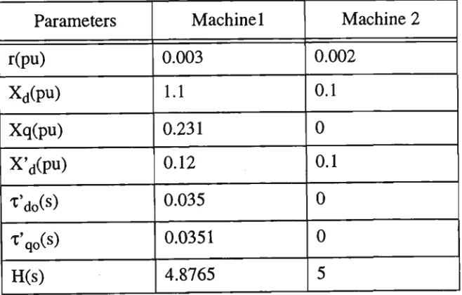
Table 3.1 Line impedances for single machine infinite bus 72 Table 3.2 Machine and Exciter parameters for single machine infinite bus 73
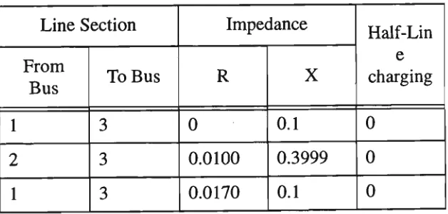
Table 3.3 Line impedances for four machine ten bus system 7 7
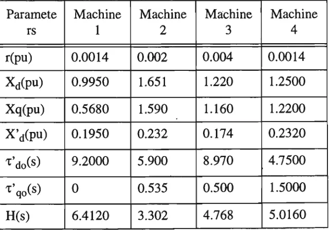
Table 3.4 Generation and Load data for four machine ten bus system 7 8 Table 3.5 Machine and Exciter parameters for four machine ten bus system 78
Table 4.1 Line Impedances for Voltage Control and Stability 95 Table 4.2 Generation and load data for Voltage Control and Stability 96
Table 4.3 Machine and Exciter parameters for Voltage Control and Stability 96
Introduction and Review
1.1 Introduction
Industrial and commercial customers are adding computer controlled and
microprocessor based equipment for automated control, information management
and robotics at an ever increasing rate [1]. O n e of the requirements for these
sophisticated devices is the need for high quality power containing minimal voltage
variations, because these devices are all susceptible to supply disturbances. The
economical and potential safety and environmental impacts of such disturbances can
be substantial, compared to residential and typical small commercial loads [2]. The performance of these sophisticated devices can be adversely affected by line voltage
sags, surges, transients and harmonic distortions in the power supply. These
disturbances can be caused by faults, circuit breaker reclosing, feeder switching
actions or switching on capacitor banks. Traditionally, the power supply is from
conventional energy sources. T h e expression conventional energy refers to power generation from coal, large scale hydro, gas and nuclear power. The expression
non-conventional energy sources covers C O G E N E R A T I O N , R E N E W A B L E
practice non-conventional energy sources are connected at the load centre through
power electronic controllers. Currently the trend is to use advanced power electronic
controllers, such as solid state circuit breakers, Dynamic Voltage Regulators ( D V R )
and Static Condensers ( S T A T C O N ) . These power electronic controllers are connected along the distribution line [1].
Private owned generating plant has the capacity to make a useful contribution
towards meeting the energy demand on the distribution network. C O G E N E R A T I O N
is the simultaneous generation of useful heat and electricity from the same primary
fuel source. Typically, the heat energy is in the form of process steam, and fuels are
either natural gas or process waste gas.
RENEWABLE ENERGY SOURCES are a manifestation of nature's primary energy.
Most of the energy captured by the earth comes from the sun in the form of light and
heat. T h e incident solar radiation energy, wind energy, biomass, tidal & w a v e energy,
hydro or water power and geothermal energy are energy sources that do not pollute
the atmosphere. Unlike fossil fuel sources these renewable energy sources do not
contribute to 'Greenhouse' effect.
Large scale hydro electric plants were the earliest to be harnessed to provide clean
energy. Fossil fuel power plants were promoted till the time it was realised that they
were one of the main causes of greenhouse gas emissions. With the development of
technology, projects that were discarded as being uneconomical are being reviewed
S T A N D B Y G E N E R A T I O N is where customers require a particularly high level of
supply reliability and/of availability and they install their o w n generating plant and
security against non-availability of supply authority sources energy because of
industrial disputes or supply interruptions. A cogeneration scheme m a y also fill a stand-by generation role.
ENERGY STORAGE refers to mainly battery, fly wheel, high pressure compress air storage and p u m p storage.
Integrating Dispersed Sources of Generation (DSG) can provide electric utilities with
a technology option that gives high quality, value added power supply suitable for
customers' sensitive loads. Connecting D S G has several impacts on the operation and protection of the whole system. This thesis relates to the analysis of dynamic
behaviour of the dispersed storage and generation unit interconnected to distribution
network in terms of its stability. Simulation studies were carried out to find the
transient stability and voltage stability of the non-conventional energy sources under
different operating conditions. A 5-second simulation w a s conducted using explicitly
numerical integration (Euler method) and an integration time step of 0.002 second. A
synchronous generator, plays the role of a D S G unit which is a c o m m o n form of
renewable energy scheme or cogenerator.
1.2 Dispersed Storage Generation
Limited availability of fossil fuels, and the d a m a g e its usage causes to the
environment has prompted active research into alternative, cleaner energy sources.
Energy sources such as wind, solar, tidal, wave, hydro, biomass and geothermal are
potential reusable/renewable energy sources. M o s t of these renewable energy sources
are not suitable for producing electric power at a continuous rate as their energy
levels fluctuate with time. Currently, these sources of energy are being utilised in
small scale production of electric power, mostly in remote areas. In s o m e cases
hybrid systems have been tried and proved that utility grade electric power can be
produced using these energy sources but still in limited capacity due to practical and
economical limitations [3] [4]. In the meantime, to limit the usage of fossil fuels, most governments are encouraging private generators. In large industries and
commercial centres where steam is required for processes and/or heating,
cogeneration is widely considered as a m e a n of combined heat and power production
to improve energy efficiency.
1.2.1.1 Significance of Cogeneration
Cogeneration, as a mean of energy efficient production of both heat and power, is
spreading in large industries and commercial centres in m a n y countries. This trend is
due to several practical and economic advantages such as:
• Energy efficiency - more efficient use of fuel with combined production of electricity and steam where steam is required for production processes and/or heating.
operation with utility supply will enhance reliability of supply to vital loads.
• Economy and reduction in environmental damage - availability of waste
fuels as a consequence of production process in s o m e industries, such as oil refineries, which can be used for firing in steam generators. This fuel is free, and burning it in the atmosphere could result in emitting more lethal gases into the environment.
• Revenue to cogenerator - opportunity for cogenerators to sell excess power to utility at profitable prices, mainly during peak d e m a n d period on the utility system.
• Having dispersed sources of generations, such as cogenerators, connected to utility system will render following advantages to utility systems:
a. Possibility of meeting short term peak demand on the utility
system b y buying p o w e r from cogenerators and thus avoiding
starting peak load plants - Peak lopping.
b. Maintain a better voltage profile throughout the system.
c. Availability of more spinning reserve in the system.
d. Possibility of accommodating more new consumers on the
existing utility network without having to augment or construct n e w transmission and/or distribution network.
one time. O n the long run, m o r e and more utilities m a y begin to realise these benefits as their system d e m a n d grows.
The advantages stated above indicate the significance of cogeneration. However, it is
to be noted that w h e n a cogenerator is connected to a utility, it becomes part of the
utility system. Such a system has several impacts on the utility and on the cogenerator, which are discussed in subsequent sections.
1.2.2 Cogeneration in United States of America
One of the intentions of the Public Utility Regulatory Policies Act (PURPA) of 1978
[5] w a s to promote the development of small, dispersed generation sources. This has
sparked m u c h interest in the American electric utility industry which has n o w been
forced to tackle technical problems associated with the interconnection of Dispersed Storage and Generation ( D S G ) devices. Under the P U R P A , Qualifying Facilities
(QFs) m a y be a unit supplying s o m e or all of an existing or n e w load, or it m a y be
renewable resources such as wind generation, or geothermal, solar, bio-mass, or mini hydro-electric generation.
Section 210(a) of PURPA also requires that each electric utility offer to sell electric
energy to a Q F . This obligation to sell power is interpreted as requiring utilities to
provide four classes of service to QF's [6][7][8][9]:
(a) "Supplementary Power", which is energy or capacity used by a QF in addition to
(b) "Interruptable Power", which is energy or capacity that is subject to interruption
by the utility under specified conditions, and is normally provided at a lower
rate than non-interruptable service if it enables the utility to reduce peak loads;
(c) "Maintenance Power", which is energy or capacity supplied during scheduled
outages of the Q F , presumably during periods when the utility's other load is
low;
(d) "Backup Power", which is the energy or capacity supplied during unscheduled
outages.
A utility may avoid providing any of these four classes of service only if it convinces
the Public Service Commission that compliance would impair its ability to render
adequate service or would place an undue burden on the electric utility.
Interconnection costs must be assessed on a non-discriminatory basis with respect to
non-cogenerating customers with similar load characteristics, and m a y not duplicate
any costs including the avoided costs. Standard or class charges for interconnection
m a y be included in purchase power tariffs for Q F s with a design capacity of 100 k W
or less, and Public Service Commissions m a y also determine interconnection costs
for larger facilities on either a class or individual basis.
Cogenerators' fuel choice may be influenced by the Fuel Use Act (FUA) prohibitions
on oil and gas use and by the allocation and pricing rules of Natural Gas Policy Act
A cogenerator m a y be subject to the F U A prohibitions if it has a fuel heat input rate
100 of million Btu per hour or greater and if it comes within the statutory definition
of either a p o w e r plant or a major fuel-burning installation. Under F U A , a power
plant includes "any stationary electric generating unit", consisting of a boiler, a gas
turbine, or a combined-cycle unit that produces electric power for purposes of sale or
exchange", but does not include cogeneration faculties if less than half of the annual
electric output is sold or exchanged for resale. A major fuel-burning installation is
defined as "a stationary unit consisting of a boiler, gas turbine unit, combined cycle
unit or internal combustion engine". However, the prohibition against the use of oil
and gas in n e w major fuel-burning installations applies only to boilers.
FUA allows a permanent exemption for cogenerators for if the "economic and other
benefits of cogeneration are unobtainable unless petroleum or other gas, or both, are
used in such facilities". T h e Department of Energy interprets the phrase "economic
and other benefits" to m e a n that the oil or gas to be consumed by the cogenerator will
be less than that which would otherwise be consumed by the conventional separate
electric and thermal energy systems. Alternatively, if the cogenerator can show that the exemption would be in the public interest (e.g., technically innovative facility, or
one that would help to maintain employment in an urban area), the Department of
Energy will not require a demonstration of oil/gas savings.
Although the permanent exemption for cogeneration is likely to be the preferred
route for potential cogenerators subject to the F U A prohibitions. Several other
exemptions m a y be applicable in certain circumstances. First, a permanent
petroleum and alternate fuel. Under this mixtures exemption, the amount of oil or gas
to be used cannot exceed the m i n i m u m percentage of the total annual Btu heat input
of the primary energy source needed to maintain operational reliability of the unit
consistent with maintaining a reasonable level of fuel efficiency. Second, a
temporary exemption is available to petitioners w h o plan to use a synthetic fuel
(derived from coal or another fuel) by the end of the exemption period. Third, a
temporary public interest exemption m a y be obtained w h e n the petitioner is unable to comply with F U A immediately (but will be able to comply by the end of the
exemption). O n e of the cases where this public interest exemption m a y be granted is
for the use of oil or gas in an existing facility during the ongoing construction of an laternate fuel-fired unit.
Natural Gas Policy Act (NGPA) of 1978 grants an exemption from its incremental
pricing provisions to qualify cogeneration facilities under P U R P A . Thus, the potential lower gas prices should not affect the relative competitiveness of gas-fired
cogeneration significantly. Moreover, plants burning intrastate gas m a y not realise
any savings because the fuel price is often at the same level as the incremental price.
In addition, the deregulation could largely remove incremental pricing. These
uncertainties m e a n N G P A probably will not be a major factor in cogeneration
investment decisions.
Cogeneration can have significant impacts on air quality, especially in urban areas.
Depending on cogenerator's size and location, it m a y be subject to one or more of the
Clean Air Act ( C A A ) provisions, including N e w Source Performance Standards
Standards ( N A A Q S ) in non-attainment and Prevention significant Deterioration
(PSD) areas.
At present, NSPS exist for two types of sources that might be used for cogeneration,
and have been proposed for a third. N S P S have been implemented for electric utility
steam units of greater than 250-MMBtu/hr. heat input. However, cogeneration
facilities in this category are exempt from N S P S if they sell annually less than either
2 5 M W or one-third of their potential capacity. T h e other promulgated N S P S is for
gas turbines of greater than 10 MMBtu/hr. heat input at peak-loads. N S P S have been
proposed for nitrogen oxide emissions from both gasoline and diesel stationary
engines. A s proposed, they would apply to all diesel engines with greater than 560 cubic inch displacement per cylinder. Finally, the Environmental Protection Agency
( E P A ) is considering N S P S for small fossil fuel boilers. T h e E P A is reportedly
considering lower limits in the range of 5 0 to 100 MMBtu/hr. heat input.
1.3 Cogeneration in Australia[10]
Cogeneration has existed in Australia since the introduction of electricity. In the early
days of electricity, industry often provided its o w n power (cogeneration where the
balance of heat and power w a s right) and the public system provided domestic and
public power.
The 1980's saw an upturn in cogeneration for environmental and economic reasons
particularly in Victoria and South Australia. In 1987 the Victorian State Government
Incentives Package and about the same time in South Australia, S A G A S C O
established a cogeneration division.
The 1990's presents an era of great opportunities and challenges for the cogeneration
industry as the energy supply industry is transformed by the break-up of vertically
integrated utilities (in Victoria) and the introduction of competition between energy
supplier and the Grid.
Cogeneration is a smart technical solution to provide heat and power to industry and
commerce in a cost effective and environmentally sound manner. Cogeneration
exists in a complex competitive and regulatory environment that has capacity to
prevent the full development of its contribution to the economy and environment.
1.3.1 Cogeneration data
No authoritative information is available on the extent of non-utility cogeneration
and power production.
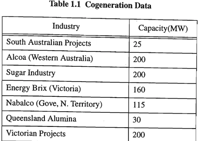
The best available estimate puts cogeneration capacity in Australia at about 1000
M W , m a d e up as follows:
1.3.2 Victorian support
Within five years, it is conservatively expected that about 500 MW of Victoria's
Table 1.1 Cogeneration Data
Industry South Australian Projects Alcoa (Western Australia) Sugar Industry
Energy Brix (Victoria)
Nabalco (Gove, N . Territory) Queensland Alumina
Victorian Projects
Capacity ( M W ) 25 200 200 160 115 30 200
renewable energy projects, the equivalent to the output from one Loy Yang power station unit.
Already, 100 MW is provided by 15 major natural gas cogenerators. In addition,
seven more cogeneration units under construction will provide another 34.4 M W .
Further 16 cogeneration projects totalling 138.6 M W and six renewable energy projects totalling 21.2 M W are committed to development.
Table 1.2 Projects operating (Installed prior to 1987)
Organisation
A P M , Fairfield and Maryvale B H P House, Melbourne Cadbury Scheweppes Kodak, Coburg
M M B W , Carrum T O T A L
M W Installed
Table 1.3 Projects installed and operational since 1987
Projects
Sirius Biotechnology Nissan Australia, Clayton Austin Hospital, Heidelberg A P M , Fairfield
Sandringham Hospital Ballarat Base Hospital Latrobe University Unilever
Kyabram Hospital
Ringwood Aquatic Centre
TOTAL Capacity (MW) 1.1 5.6 3.8 7.5 0.2 2.0 6.0 10.0 0.5 0.1 36.8 Type Reciprocating Engine Gas Turbine Gas Turbine Steam Engine Reciprocating Engine Reciprocating Engine Gas Turbine Gas Turbine Reciprocating Engine Reciprocating Engine
Table 1.4 Projects constructed in 1990s
Hospitals "Big 6" Hospital Project, Dandenong and District Royal Melbourne
Geelong
A n n Caudle Centre Alfred Hospital St. Vincent's
Grace McKellar Centre
1.3.3 S E C Support for cogeneration
Background
Victoria has traditionally relied on its plentiful brown coal resources as a source of
base load electricity and on natural gas and hydro for its peak load. It is clear,
however, that great potential exists for industry and commerce to contribute
economically to electricity production through cogeneration.
The Victorian Government has given cogeneration a high profile and its support for
the development of the technology w a s outlined in the Government Economic
Strategy Paper - "Victoria the Next Decade" released in 1984. This was followed by
the Government's paper in June 1989 on the Greenhouse Challenge outlined Cogeneration as one of the vehicles to minimise atmospheric emissions of
greenhouse gases.
The SEC has adopted the Government's policies in its Cogeneration and Renewable
Energy Strategy. This strategy includes:
• encouraging the efficient use of fuel and helping its customers gain
the benefits of energy efficiency from cogeneration and renewable energy projects;
promoting ways of reducing levels of C 02 emission into the
considering opportunities for joint ventures in potential cogenera-tion and renewable energy schemes;
encouraging and promoting commercially viable projects by
intro-ducing incentives to stimulate interest in cogeneration and renewa-ble energy projects;
encouraging the development of a professional and effective cogen-eration and renewable energy industry.
To further the commitment in promoting cogeneration in Victoria the following measures are taken:
providing a market for cogenerated power by enacting a statutory commitment to purchase the power.
providing reasonable buyback rates for cogenerated power that reward cogenerators but are not subsidised by other customers. This can be done by buying excess power at the SEC's avoided cost, that is, the amount the S E C saves by not generating the power itself.
• making payments to cogenerators w h o guarantee the availability of future capacity. These payments reflect the amount the S E C saves by the deferral or elimination of the need for s o m e future power sta-tions.
• adopting a n e w approach to stand-by supplies to remove current dis-crimination against cogenerators.
cogen-eration projects to proceed.
1.3.3.1 Examining fuel policies and prices
In recognition that a high proportion of potential cogenerators are
n o w burning natural gas to produce process heat or steam, users should be encouraged to convert to cogeneration as a small addition amount of gas burned can yield an overall energy saving.
• Encourage the use of coal in cogeneration systems.
Examining the pricing structure of natural gas for cogeneration. Evaluation of the merits of a separate cogeneration gas tariff and its effect on the existing Government gas pricing policy.
• Encourage the use of renewable fuels and residues through provi-sion of Government financial incentives.
• Provide financial assistance for feasibility studies for projects that on initial assessment look technically feasible and economically viable.
• Encourage projects to serve as local models and using early studies to evaluate effectiveness of efforts to promote cogeneration.
The key elements of the SEC incentives package for projects smaller than 10
Megawatts are:
S E C interconnection costs are repayable over the contract period,
S E C buyback rates up to 10 M W are tied to the SEC's tariff rate and are linked to C P I increases,
financial assistance is available for feasibility studies for special projects,
a 10 year contract period that allows for escalation in buyback rates.
In 1987, the SEC in conjunction with the Victorian Government took the initiative by
launching the "Cogeneration and Renewable Energy Incentive Package" to further encourage the smaller potential cogenerators.
1.3.3.2 Encouraging Co-generation in private and public sectors
• Carrying out a detailed examination of cogeneration potential into pub-lic facilities e.g., hospitals, universities, libraries, nursing h o m e s etc.
• mstalling and promoting the installation of cogeneration plants instead of constructing additional n e w central power stations.
• Encouraging financing of Private and Public sector projects by outside investors.
1.3.3.3 Undertaking an information and technical assistance program
• Developing a marketing plan to promote the development and wider use of cogeneration.
arising from cogeneration in the community, particularly the industrial and commercial sectors.
• Establishing a Cogeneration Advisory Group to help potential cogen-erators and provide a consultative service.
Some people are still surprised that the SEC synonyms with what they believe is a
power monopoly, should be promoting alternative production. T h e reasons are not
only economically and environmentally sound, but also ensure efficient utilisation of
the State's resources. It costs the Commission about $1.3 million to produce one
Megawatt of power. Therefore 500 M W of cogeneration power will save it $650
million in capital expenditure. T h e S E C benefits directly by avoiding capital
borrowing, particularly for the construction of n e w power stations. In 1994 a process
for a great deal of change began w h e n the breakdown and privatisation of S E C
commenced. T h e first step towards privatisation of S E C w a s the break up of the company into separate business groups, such as Generation, Transmission and
Distribution. T h e n each of these groups were further broken up with respect to the
area of Distribution. T h e supply of power throughout Victoria is n o w the
responsibility of five distribution companies. These are United Energy, Eastern
Energy, Solaris Power, CitiPower and Powercor Australia.
Cogeneration also creates new electricity supplies much faster than the Commission
could plan and build n e w power stations, which take m a n y years from inception to
production. Small generation plants whether cogeneration or renewable also meet
environmental licensing requirements more easily than a n e w central power station.
system losses.
1.4 Integration of Dispersed Storage Generation
One of the important reasons for parallel operation of a cogenerator with a utility, as
mentioned earlier, is to maintain reliable supply to vital local loads. Therefore, it is of
paramount importance to secure a cogenerator from tripping, following separation
from the utility, for any abnormality on the utility system. A cogenerator separated
from the utility m a y b e c o m e unstable and trip due to generation - demand mismatch on the cogeneration system. T o secure the cogenerator from such an event, proper
decision making, and faster, control is necessary on the cogenerator. T h e control must be fast enough to bring the cogenerator back to stable and normal operating
conditions before any protection relay operates. Also, such control is necessary to
prevent any d a m a g e to cogenerator or any plant supplied by the cogenerator [11].
Over the last decade there has been a growing interest in the installation of small and m e d i u m sized generation units which operate in parallel with the local electric
utility's p o w e r supply defined as Dispersed Storage and Generation ( D S G ) . T h e
utilities' objective has been to ensure that the presence of the D S G unit will not
detract from the quality of supply to all customers connected to their system [12].
The major areas of concern are:
1. the adequacy of present protection practices and hardware for electric
2. protection consideration other than surge protection, associated with the
connection of small D S G s to the utility distribution lines [13];
3. the issue of the effect of synchronous generators with different kinds of exciter
control as well as induction generators and constant extinction angle inverters
with or without capacitor compensations on the voltage in the distribution system as load and generated power vary [15];
4. the issue of power constraint of the cogeneration process, control of tie-lines to
cogeneration plants, voltage support, energy response and maintenance [14];
5. the issue of technical planning problem associated with system protection, under frequency load shedding and needs for long term operation planning
[16];
6. the issues such as outage planning, services restoration, special relay protection under operating problems with cogeneration on distribution systems needs to be
considered [17].
For effective operation as part of the utility, a DSG must be integrated. Integration is
defined as follows:
1) a DSG connection to a utility system in which provisions are made for
2) the operation of the D S G as managed part of the total utility supply system.
3) A single DSG unit of relatively small output, or a number of DSG units of
whose aggregate output is small, may be connected to a system without being
integrated i.e., they may be connected but not integrated as a managed part of
the supply mix. Integrated operations require interaction among the DSGs and
the power system, including the electric utility's bulk supply systems.
1.4.1 Operational Problems
Cogeneration has impacted the utility generation due to their base load mode of operation. This base load usually compounds the utility's daily unit commitment
problems associated with unit cycling, control reserves, and minimum load. The
utility experiences a significant decrease in operating flexibility. Base load cogeneration effectively removes constant load of this utility. The worst case
scenario is a cogenerator who sells to the utility only during the off peak, termed off peak dumping. To avoid this undesirable situation, four different types of contracts
are advised:
• Firm capacity contracts
• Non-firm energy sales only contract
• Wheeling contracts
T h e operational problems from cogenerator's point of view are that the basic
philosophy behind design of QF generating facilities are much different than that
typically used by utilities. Where the utility must design to meet the growing and
periodically swinging electrical loads, the QF's concerns he primarily with meeting
thermal demands of manufacturing processes. Design of electrical capabilities then
follows, but does not usually constitute the primary design constraint.
It is often difficult to comply with the expectations of and rules imposed by utilities.
In some cases, this compliance is realised at significant economic expenses.
IEEE formed a Working Group on Current Operational Problems (COPS) with the
goal of focusing attention of the industry on problems faced by those who are
involved in actual power. Eight system operational areas are identified:
• operations planning
• normal systems operations
• emergency system operations
• system restoration
• interconnections and pooling
• dispatcher selection and training
• system operations management
T h e group surveyed, conducted numerous technical sessions and published papers.
T h e mathematical modelling aspects of various types of cogeneration facilities along
with the linear program optimisation procedures implemented to arrive at optimum
operational schedules have been reported.
The aspects of energy management most impacted by DSG are associated with real
time control. Automatic generation control ( A G C ) can be influenced by the addition
of D S G s within the control area. T h e position of a scheduled D S G is dependent upon
considerations of economic dispatch, and will also depend on the resource of the
D S G . A G C is affected in two ways by unschedulable D S G s . First, the position in the
loading order must be determined, but unlike the case of a scheduled D S G , the addition of a considerable penetration of uncontrollable power sources could
influence existing generation.
If a DSG has independent voltage control capability, it can and must be operated
cooperatively with any method of D S G voltage control on existing power system.
Protection of radial feeders is generally by breakers or reclosures at the distribution
substation, tripped by the action of an overcurrent relay. Protection of laterals and
transformers is generally by use of fuses, including current limiting types. Intertie
protection schemes using undervoltage, overvoltage, underfrequency, overfrequency,
voltage-controlled or voltage compensated, batter/DC undervoltage, reverse power
are reported by the P o w e r System Relaying Committee of I E E E [13]. T h e committee
has prepared a consumer-utility guide to establish a c o m m o n understanding amongst
S o m e changes in the safety practices and protection hardware are required for low
penetration of D S G devices. Additional feeder switches and lock-out disconnect
switches at the D S G installations would reduce the size of feeder sections with D S G
and prevent the re-energisation of a de-energised feeder section during maintenance.
Because of D S G infeed to faults, fuse sizes m a y need to be increased and reclosure
settings delayed to prevent d a m a g e to D S G devices operating out of-phase with the
utility system following the occurrence of a system disturbance. T h e placement of
capacitors to correct the power factor must take into consideration the possibility of D S G islanding and resonant overvoltage situations.
Automated systems and microprocessor-based protection packages may be a more
practical and safer method for controlling the operation of D S G devices and
protecting and distribution system.
Also, the small storage and generation systems connected to the distribution system
are expected to increase in importance as industrial cogenerators [15]. H o m e owners
with solar arrays or wind turbines and utility with small hydro resources seek to hold
d o w n their energy costs. A s the amount of generation and storage provided in this
w a y increases, the need to control and monitor them in an integrated fashion will
become increasingly evident [16]. While providing economic and environmental
benefits, D S G s can create economic, technical, legal and safety concern for the
owners, the electric utilities, and other utility customers [16].
Further literature survey indicates that current interest of research on dispersed
interconnection with power utilities for parallel operation. In that, m o r e focus is
given for the protection of a utility inter-tie with a cogeneration facility. T h e
protection requirements on an inter-tie and the complexity in coordinating such
protection will depend o n the type of connection and operating voltage level [18].
In an industrial power system where a cogenerator is connected to a common high
voltage busbar with the utility supply and local distribution feeders, it is important to
accurately locate and isolate any fault. Fault can be on the industrial generator, on an
industrial distribution circuit, on the utility interconnection, or on s o m e other utility
circuit. Fast and dependable fault discrimination technique is important for fast
clearance of any fault and at the s a m e time to avoid nuisance tripping of any plant.
Salman and Mollah [19] have presented a technique to detect, locate and identify a
fault on such an integrated system. This technique is based on detection of reversal of
current flow directions at various locations in the system. T h e logic used to locate a
fault is dependent o n the current flow direction on the inter-tie as well. Therefore, it
should be noted that, from an exact or near float condition, a small fluctuation of
power flow on the inter-tie, possibly due to a sudden change of industrial load, can be
interpreted, as per the logic, as a three phase fault on an industrial distribution circuit.
Instead of comparing only the signs of the imaginary component of the complex
current as suggested by Salman and Mollah [19], a current magnitude check as well m a y avoid this ambiguity. This method can be easily applied for a simple system
configuration. However, for complex cases like a tap off inter-tie and an integrated
1.5 P o w e r Electronic Controllers
In the last 30 years, power electronic applications have arisen in electrical power
transmission systems primarily in high-voltage direct current transmission. In the last
15 years, however, there has been substantial installation of Static Var Compensators
(SVCs) connected to A C transmission lines[17]. Because of the success of these
systems the idea of Flexible A C Transmission System ( F A C T S ) evolved. F A C T S
includes a n e w generation of systems based on power electronic devices which are
capable not only of being switched on but also of being switched off. A n example is
the Gate-turn-off ( G T O ) thyristor [20]. T h e concept of "Custom Power" which
focuses on reliability and quality of power flow, has been familiar to a specialised
group of distribution engineers since 1988 [1].
Anticipated developments in the utility industry will enlarge the potential for
"Custom Power". Superconducting magnetic energy storage was originally proposed
for use by utilities to help them meet peak electricity demands. In 1970's feasibility
studies in the United States resulted in conceptual design of a large Superconducting
Magnetic Energy Storage ( S M E S ) system. In 1988, Superconductivity Inc. began
examining applications of smaller S M E S units for power qualities uses, which
demand rather little in the w a y of energy storage but quite a lot in the w a y of power
delivery. In 1992, an integrated quench detection and protection system for the
S M E S w a s developed at M o n a s h University [21]. In 1993, optimal application of
O n e of the key components of the distribution network is the power electronic
controllers. Improved capabilities and availability of power semiconductor devices
and microprocessors have lead to electronic control of distribution systems. Electric
Power Research Institute (EPRI), through its Flexible A C Transmission System
( F A C T S ) program which allows a greater control of power flow and a secure loading
of transmission lines to levels nearer to their thermal limits, has developed power
electronics technology to achieve better control of utility's transmission systems.
Further, these devices can reduce distribution system and customer losses. These
efforts will prove useful for the development of distribution class controllers [20].
Prototype circuit breakers and static condensers are based on gate turn-off ( G T O )
thyristor technology and are designed for applications on 15 k V distribution systems.
T h e final version of both controllers are based on advanced metal oxide silicon
( M O S ) controlled thyristor [1].
1.6 Storage Batteries
Storage batteries represent another key component of the distribution network.
Energy storage that could curtail peak d e m a n d w h e n the most difficult operational
problems occur offers a promising approach. Major developments and the
corresponding benefits are as follows:
1. Micro SMES technology has advantages compared to battery, capacitor,
flywheel, and other energy storage systems, in terms of its characteristics such
as energy density, charge-discharge-cycle efficiency, environmental effects and
applications than others. S o m e are best suited for charge-discharge times
measured in hours, whereas others are best for millisecond cycles.
Power-delivery levels can range from a few to thousands of kilowatts [23].
2. Battery management system (BMS) using the latest semiconductor control
devices focuses on maximising the discharge and recharge efficiency of an
operating battery. This is done by monitoring and controlling individual cell
performance at m i n i m u m cost. T h e system can predict battery energy balance
by estimating deliverable service capacity at each cycle and it can also estimate
capacity returned during regenerative braking in an operating battery [24].
3. While significant progress has been made in obtaining higher performance and
longer battery life, the microprocessor based B M S has b e c o m e a more valuable
tool with remote site installations. Instantaneous data retrieval, detailed history
data bases, and automated system adjustments without the need of additional
personnel are s o m e of the attractive benefits associated with the investment in a
B M S [25].
4. The primary benefit obtained by using micro-computer equipment in battery
monitoring applications appears to be the reduced need for routine maintenance
once such a system is installed [26].
5. The system designer can partition the battery management functions to get
m a n y advanced functions presently supported by intelligent battery packs in a
supply at significant lower system cost [27].
6. One overriding concern pertaining to batteries and power sources in general is
the need to avoid a proliferation of battery types. T o minimise proliferation, a standard family of batteries, both primary and rechargeable have been identified for future needs. They are:
High energy density primary batteries to serve as the next
genera-tion of general purpose high energy density batteries, as well as m a x i m u m energy density batteries for use in selected applications.
• Improve rechargeable batteries for use in power equipment for com-m a n d , control, cocom-mcom-munications, cocom-mputer and intelligence uses.
• Improved reserve/fuse batteries for use in hthium-based and longer life batteries for delivering a few kilowatts for several minutes.
• Pulse batteries and capacitors for use in mobile applications, which deliver power on the order of several M J in few milliseconds.
• Portable fuel cell systems: there is an on-going and increasing need for lighter weight power sources for use in a range of portable applications. Backpack fuel cell "batteries" powered by hydrogen, m e n -thol, or eventually diesel fuel, have the potential to exceed the energy density of a battery, since they can use air as the oxidant.
1.7 Further Reviews
Other literature review reveals that placement of variety of controllers can require
significant coordination to ensure proper operation under variety of circumstances
[29].
Power system studies have been carried out using the network configuration
containing a D S G unit to examine the requirements of an islanding, or 'loss of grid',
protection and outlines the principal methods used for this type of relaying. A n e w
protection algorithm has been introduced which is based on the rate of change of
power as measured at the generator's terminal [30].
Computer modelling has been carried out to verify the PV power system operation
and to examine the transient effects [31].
Further literature survey in the subject reveals that significant amount of work has
been carried out so far on control of D S G or cogeneration system, operating in
parallel with utility [30]. W o r k on modelling of photovoltaic cell has also been
carried out [31]. However, the research to date has not provided enough information on h o w the system behaves under different operating conditions, w h e n
non-conventional energy sources are connected to a system. T h e proposed research
will provide m u c h of the information that is required w h e n non-conventional energy
sources are connected to a distribution system.
provides the lowest cost solution. Surveys [30],[31] have been carried out with the application of a variety of controllers along with the D S G s and h o w they interact with each other to provide the needed response to attend to the various contingencies. Distribution network with such components has been modelled to find out the voltage drop, transients, fault level and optimisation. Also planning and careful implementation of software control for protection and associated strategies to bring about the smooth and effective operation of various controllers connected in the distribution network has been discussed.
Most of the distribution companies have been concerned about the impact of non-conventional energy on the operation of their distribution systems. T h e following are s o m e of the advantages of implementing this combined system in the distribution companies:
1. better demand forecasting, particularly at peak periods;
2. planning for new substations, uncertain load growth will be possible;
3. adequacy of distribution alternatives can be tested for different operating conditions;
4. distribution alternatives can be examined on the basis of the contingency analysis considering credible line outage conditions.
5. system capacity can be tested for returning to synchronism after recovery following a major system fault.
1.8 Scope and Objective
The objective of the project is to model a distribution network with dispersed storage
and generation ( D S G ) so as to generate and distribute high quality, value added
power to customers in a stable (sustaining small disturbances), viable (currents, voltage, angle and frequencies within tolerances) and optimal supply.
A computer simulation package using Power System Toolbox under MATLAB
environment has been developed that has incorporated the above network model and that will provide an inexpensive and reliable method of examining the above system
problems. It is envisaged that in future, such concerns as power quality and control
optimisation will be addressed using computer models.
The main objectives of this thesis are:
1. To develop a mathematical model to test the responses of the distribution
system to the following:
• voltage stability,
• transient conditions,
• fault conditions,
and to design a network for the future.
transient effects, short circuit and stability of systems. T h e analysis will help to
determine the ratings of protective devices to study voltage sensitivity of the
components of the system, and to establish w h e n cables, transformers and lines
are overloaded.
1.9 Originality of Thesis
1. A mathematical model for the configuration has been developed. The
formulation of fundamental equations is based on estabhshing explicit relations
between the system dynamic components. T h e Power System Toolbox package has been used to solve the coupled non-linear fundamental equations for
impedance and high frequency losses.
2. The computer simulation is performed as a part of the study to address the
adequacy of the electric utility industry's present protection practices on the
distribution system with D S G s . Simulation considers phenomena such as
voltage drop, transient effects, short circuit effect and sensitivity.
3. The harmonics of the system has been examined by making use of the
equations that couple inductance and capacitance. It is planned to optimise
these systems to minimise the magnitudes of the harmonics.
4. The model can be used to calculate all necessary momentary, interrupting and
5. System data used for the above studies and their results are documented for
analysis and implementation of most appropriate protection algorithm for the
configuration.
1.10 Development of Thesis
The development of the subject matter of the investigation reported in the thesis is on
the following lines:
Chapter 1: The first chapter explains the issues of Disperse Sources Generation
and review of the non-conventional energy sources.
Chapter 2: This chapter explains the mathematical theory on which the models
are based and the describe the capabilities of the Power System
Toolbox program.
Chapter 3: In this section we will study the small-signal performance of a
single synchronous machine which is considered as a
non-conventional energy source connected to a large system
through distribution lines. Transient stability study of
Multi-machine multi bus system also considered.
Chapter 4: The aim of this section is to analyse the variation in voltage of the distribution network w h e n renewable energy sources interconnected
study analyses the impact of interconnection of small synchronous generators to the utility p o w e r grid.
Chapter 5: This chapter describes the salient features of the distribution system
characteristics. Operational problems like voltage control,
harmonics, earthing, reliability etc. are considered. Regulatory and
contract issues are also outlined.
Chapter 6: In this section, a review of distribution system protection & control strategies and hardware w a s carried out to establish 'state-of-the-art' technology currently employed.
Chapter 7: This chapter offers the main conclusions derived from the observed
Mathematical Modelling
2.1 Introduction
The objective of the Distribution network is to generate and to distribute power to its customers in a
• stable (sustaining small disturbances);
• viable (currents, voltages, angles and frequencies within tolerances);
• optimal fashion (economy).
transients, fault level and optimisation along with planning and careful implementation of software control for protection are the strategies to bring about the smooth and effective operation of various controllers connected in the distribution network.
DS
-f-220/66
1
FEEDER1I LOAD I
kV
FEEDER2 66/22 kV
ISTATCONl
^ 22 kV/415 V I
1
©
LOAD! GENERATORFigure. 2.1 A distribution network connected with a cogenerator
SSB SOLID STATE CIRCUIT BREAKER STATCON STATIC CONDENSOR
LC INDUCTOR A N D CAPACITOR .
D S DISTRIBUTION SUBSTATION
2.1.1 State-Space Representation
by a set of n first order nonlinear ordinary differential equations of the following form:
*i = /;(xi,x2,....xn; u1,u2,....ur; t) i=l,2,....n (2.1)
where n is the order of the system and r is the number of inputs. This can be written in the following form by using vector-matrix notation:
X. =f(x,u,t) (2.2)
where
X =
xl
x2
xn
u =
ul
u2
un
f =
fl fl
fn
T h e column vector x is referred to as the state vector, and its entries x-. as state variables. T h e column vector u is the vector of inputs to the system. These are the external signals that influence the performance of the system. T i m e is denoted by t, and the derivative of a state variable x with respect to time is denoted by x. If the derivatives of the state variables are not explicit functions of time, the system is said to be autonomous. In this case, above equation simplifies to:
x = f(x,u) (2.3)
T h e output variables which can be observed on the system, m a y be expressed in terms of the state variables and the input variables in the following form:
y = g(x,u) (2.4)
yi g\
y= y2 8= g2
ym\ [j>m
The column vector y is the vector of outputs, and g is a vector of nonlinear functions relating state and input variables to output variables.
2.1.1.1 The concept of state
The concept of state is fundamental to the state-space approach. The state of a system represents the m i n i m u m amount of information about the system at any instant in
time to that is necessary so that its future behaviour can be determined without reference to the input before to.
Any set of n linearly independent system variables may be used to describe the state of the system. These are referred to as the state variables; they form a minimal set of
dynamic variables that, along with the inputs to the system, provide a complete description of the system behaviour. A n y other system variables m a y be determined from a knowledge of the state.
input is non-zero, the system state will change with time. T h e set of points traced by the system state in the state space as the system m o v e s is called the state trajectory.
2.1.1.2 Equilibrium (or singular) point
The equilibrium points are those points where all the derivatives x h x2,....,xn are simultaneously zero; they define the points o n the trajectory with zero velocity. T h e system is accordingly at rest since all the variables are constant and unvarying with time.
The equilibrium or singular point must therefore satisfy the equation
f(xo) = 0 (2.5)
where x0 is the state vector x at the equilibrium point.
If the functions fi(i=l,2,....n) in the above equation are linear, then the system is linear. A linear system has only one equilibrium state (if the system matrix is non
singular). For a nonlinear system there m a y be m o r e than one equilibrium point.
The singular points are truly characteristic of the behaviour of the dynamic system, and therefore one can draw conclusions about stability from their nature.
2.1.1.3 Stability of a Dynamic System
The stability of a linear system is entirely independent of the input, and the state of a stable system with zero input will always return to the origin of the state space,