IJISET - International Journal of Innovative Science, Engineering & Technology, Vol. 2 Issue 4, April 2015. www.ijiset.com
ISSN 2348 – 7968
995
ASIC Implementation and FPGA Validation of IMA ADPCM
Encoder and Decoder Cores using Verilog HDL
Rafeedah Ahamadi Galagali
Electrical and Electronics, B L D E A’s V.P Dr.P.G.Halakatti college of Engg & Tech., Bijapur-586103, Karnataka, India
Abstract
The audio signals are needed to be compressed for mass storage, digital telephony, and internet based voice transmission. The lossy technique used in this paper is IMA ADPCM which reduces the bandwidth in voice communication. This paper discusses about audio compression of .wav file. The file is compressed ¼ of the size of the original file. After compression, the sound quality of the audio file is maintained reasonably. SCILAB software model is proposed for generating the test vectors from audio file. Implementation is done on FPGA as well as on ASIC. It uses the verilog as Hardware description language(HDL).
Keywords: ADPCM, Audio compression, IMA, Verilog.
1.Introduction
Digital audio compression allows the efficient storage and transmission of audio data. The various audio compression techniques offer different levels of complexity, compressed audio quality, and amount of data compression.
Digital Audio Data
The digital representation of audio data offers many advantages: high noise immunity, stability, and reproducibility. Audio in digital form also allows the efficient implementation of many audio processing functions (e.g., mixing, filtering, and equalization) through the digital computer.
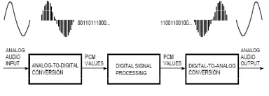
The conversion from the analog to the digital domain begins by sampling the audio input in regular, discrete intervals of time and quantizing the sampled values into a discrete number of evenly spaced levels. The digital audio data consists of a sequence of binary values representing the number of quantizer levels for each audio sample. The method of representing each sample with an independent code word is called pulse code modulation (PCM). Fig 1 shows the digital audio process.
Fig. 1. Digital audio process
2. Adaptive Differential Pulse Code Modulation
Figure below shows a simplified block diagram of an Adaptive differential pulse code modulation (ADPCM) coder. For the sake of clarity, the figure omits details such as bit-stream formatting, the possible use of side information, and the adaptation blocks. The ADPCM coder takes advantage of the fact that neighboring audio samples are generally similar to each other. Instead of representing each audio sample independently as in PCM, an ADPCM encoder computes the difference between each audio sample and its predicted value and outputs the PCM value of the differential. Note that the ADPCM encoder (Figure a) uses most of the components of the ADPCM decoder (Figure b) to compute the predicted values.
The quantizer output is generally only a (signed) representation of the number of quantizer levels. The dequantizer reconstructs the value of the quantized sample by multiplying the number of quantizer levels by the quantizer step size and possibly adding an offset of half a step size. Depending on the quantizer implementation, this offset may be necessary to center the Dequantized value between the quantization thresholds.
996
values. This side information can serve two purposes. First, in some ADPCM schemes the decoder needs the additional information to determine either the predictor or the quantizer step size, or both. Second, the data can provide redundant contextual information to the decoder to enable recovery from errors in the bit stream or to allow random access entry into the coded bit stream.
3. Interactive Multimedia Association (IMA)
The following section describes the ADPCM algorithm proposed by the Interactive Multimedia Association (IMA). This algorithm offers a compression factor of (number of bits per source sample)/4 to 1. Other ADPCM audio compression schemes include the CCITT Recommendation G.721 (32 kilobits per second compressed data rate) and Recommendation G.723 (24 kilobits per second compressed data rate) standards and the compact disc interactive audio compression algorithm.
The IMA ADPCM Algorithm
The IMA is a consortium of computer hardware and software vendors cooperating to develop a de facto standard for computer multimedia data. The IMA’s goal for its audio compression proposal was to select a public-domain audio compression algorithm able to provide good compressed audio quality with good data compression performance. In addition, the algorithm had to be simple enough to enable software-only, real-time decompression of stereo, 44.1-kHz-sampled, audio signals on a 20-megahertz (MHz) 386-class computer. The selected ADPCM algorithm not only meets these goals, but is also simple enough to enable software-only, real-time encoding on the same computer.
The simplicity of the IMA ADPCM proposal lies in the crudity of its predictor. The predicted value of the audio sample is simply the decoded value of the immediately previous audio sample. Thus the predictor block in Figure above is merely a time-delay element whose output is the input delayed by one audio sample interval. Since this predictor is not adaptive, side information is not necessary for the reconstruction of the predictor.
Fig. 2 shows a block diagram of the quantization process used by the IMA algorithm. The quantizer outputs four bits representing the signed magnitude of the number of quantizer levels for each input sample.
Fig. 2. IMA ADPCM quantization.
Adaptation to the audio signal takes place only in the quantizer block. The quantizer adapts the step size based on the current step size and the quantizer output of the immediately previous input. This adaptation can be done as a sequence of two table lookups. The three bits representing the number of quantizer levels serve as an index into the first table lookup whose output is an index adjustment for the second table lookup. This adjustment is added to a stored index value, and the range-limited result is used as the index to the second table lookup.
The summed index value is stored for use in the next iteration of the step-size adaptation. The output of the second table lookup is the new quantizer step size. Note that given a starting value for the index into the second table lookup, the data used for adaptation is completely deducible from the quantizer outputs; side information is not required for the quantizer adaptation.
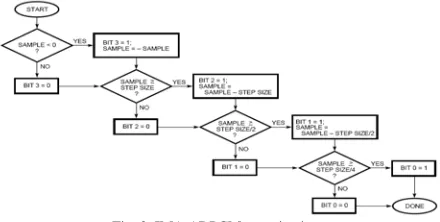
Fig. 3 illustrates a block diagram of the step-size adaptation process, and Tables 1 and 2 provide the table lookup contents.
Fig. 3. IMA ADPCM Step-size Adaptation
IJISET - International Journal of Innovative Science, Engineering & Technology, Vol. 2 Issue 4, April 2015. www.ijiset.com
ISSN 2348 – 7968
997
4. Block Diagram of the IMA ADPCM Encoder
and Decoder to be implemented
In order to implement the IMA ADPCM Encoder and Decoder cores onto Xilinx FPGA, the architecture mentioned in page 3 and Page 6 are enhanced to give more clarity on the bit operations at each level of Encoder and Decoder.
Figures 4 & 5 represent the architecture of IMA ADPCM Encoder and IMA ADPCM Decoder respectively. The same architecture has been considered in Verilog HDL implementation.
IMA ADPCM Encoder Architecture:
Fig. 4. Architecture of IMA ADPCM Encoder Core
IMA ADPCM Decoder Architecture:
Fig. 5. Architecture of IMA ADPCM Decoder Core
5. Implementation Steps
6. Software and Hardware requirements
1. SCILAB – A free version of MATLAB kind of mathematical modeling software
2. Xilinx Spartan 3AN Evaluation kit for validation purpose
3. Xilinx ISE and Xilinx Chipscope Pro software --For ASIC Design
4. Cadence Incisive Verilog HDL simulator 5. Cadence Encounter RTL Compiler
te re S T te sa w sa te in T si si b w S T A in re
est vectors fro esult.
Fi
Simulation Res
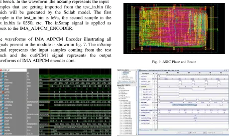
The IMA ADP est bench. In th amples that ar which will be
ample in the t est_in.bin is 0 nputs to the IM
The waveform ignals present ignal represen ench and th waveforms of IM
Fig. 7. I
Simulation Res
The fig. 8 repre
ADPCM Decod
nput signal for
epresents the o
om audio file
ig. 6. test_in.bin fi
sults for IMA
CM Encoder g he waveform ,t
re getting imp generated by test_in.bin is f 0350, etc. The MA_ADPCM_E
s of IMA AD in the module nts the input he outPCM1
MA ADPCM e
IMA ADPCM Enc
sults for IMA
esents the input
der module. Th
r the IMA AD
output of the IM
es. Fig. 6 sho
ile (from scilab mo
ADPCM Enc
gets the input he inSamp rep ported from th y the Scilab
fe9a, the seco e inSamp sign ENCODER.
DPCM Encod is shown in fi samples comi
signal repres encoder core.
coder Test bench w
ADPCM Dec
t and output sig
he inPCM sign
PCM decoder
MA ADPCM d
ows the SCIL
odel)
coder Module
samples from presents the inp he test_in.bin model. The f ond sample in nal is applied
er illustrating ig. 7. The inSa
ng from the sents the out
waveforms
coder Module
gnals for the IM
nal represents
and the outSa
decoder. LAB the put file first the d as all amp test tput MA the amp The SCI Fig. The ASI Figur This pa Validati used for and resu Thus, th is desir Since t utilizatio
ILAB software
8. The simulation
IC implementa
Fig.
re 10. IMA ADPC
aper includes t ion of IMA A r audio compre ulted in a com he compression ed for many the ASIC de on of the chip i
7.
Resu
e model is prop
n results for IMA A
ation is as show
9. ASIC Place and
CM Xilinx Chipsco
8.
Conclu
the ASIC Imp ADPCM Enco
ession of .wav mpressed file i. n leads to bette
applications i esign flow is
is very less.
ults
posed for gener
ADPCM Decoder m
wn in fig. 9.
d Route
ope Implementation
usion
plementation a der and Deco v file using ver
.e ¼ of the or er storage sche in communica s proposed, t
IJISET - International Journal of Innovative Science, Engineering & Technology, Vol. 2 Issue 4, April 2015. www.ijiset.com
ISSN 2348 – 7968
999
References
[1]
“Design and Implementation of ADPCM Based Audio
Compression Using VHDL”, 2012 International Conference on Information and Network Technology (ICINT 2012). [2] DhanashriGawali, Nirija Varma, Tejashri Dixit and SnehaMandowaraInternational Conference on Information and Network Technology IPCSIT vol. 37 (2012) © (2012) IACSIT Press, Singapore.[3] Fred Halsall “Multimedia communications” applications, networks, protocols and standards, 2004.
[4] Mat Hans and Ronald W. Schafer “Lossless compression of digital audio” IEEE SIGNAL PROCESSING MAGAZINE, 1053-5888/01, JULY 2001, pp 21-32.
[5] Davis Yen Pan, “Digital Audio Compression”, Digital Technical Journal Vol. 5 No. 2, Spring 1993.
[6] IMA ADPCM Encoder / Decoder Core Specifications, WiCores Solutions.
[7] Spartan-3A/ 3AN Starter kit Board user guide. [8] Scilab for very beginner by scilab enterprises.
[9] Weng hook “ASIC design flow by verilog coding for logic synthesis”
[10] “Chipscope pro” software provided by Xilinx all programmable.
Biography
Rafeedah Ahamadi Galagali received the bachelor’s degree in Electronics and Communication from Visveswaraya Technological University, Belgaum,
B L D E A’s V.P Dr.P.G.Halakatti college of Engg & Tech., Bijapur, Karnataka, India in 2013. Final year student of Master of Technology in Micro Electronics and Control Systems from
Visveswaraya Technological University, Belgaum, B L D E A’s V.P Dr.P.G.Halakatti college of Engg & Tech., Bijapur, Karnataka, India.