CSEIT1833777 | Received : 05 June 2018 | Accepted : 15 June 2018 | May-June-2018 [ (3)5 : 753-758 ]
© 2018 IJSRCSEIT | Volume 3 | Issue 5 | ISSN : 2456-3307
Modelling and Simulation of Microgrid during Islanding and
Optimization of Distributed Energy Resources
Bhavya BansalDepartment of Electrical Power and Energy System, Ajay Kumar Garg Engineering College , Ghaziabad, India
ABSTRACT
This paper presents a simulation and mathematical model of Microgrid in Autonomous mode. A Microgrid consist of renewable energy sources such as Solar PV system , Fuel cell stack system , Battery energy storage system (BESS) and load. Comparative study of sinusoidal PWM and space vector modulation is done and SVPWM is preferred in controlling of inverter due to its advantage over SPWM. Optimization of DER’S is done to utilize the resources at most keeping the cost in mind.
Keywords : Microgrid, Solar PV system, space vector PWM, Sinusoidal PWM, Islanding operation and inverter.
I.
INTRODUCTIONTo reduce CO2 emission , main cause of Global warming , we need to switch to renewable energy sources from conventional sources. Microgrid is the main focus area and need of hour due to increase in global temperature and climate change. A Microgrid can be defined as a low voltage distribution system to which small modular generating systems are to be connected. It can be installed in a village or town. MG is intended to operate in the following two operating modes.
GRID CONNECTED MODE: In this mode, MG is
connected to main utility grid through a point of common coupling (PCC) switch. MG feeds the load connected to it, wherever MG supplies more than required then it can feed to main grid and when demand is more than the power supplied by Microgrid then main grid helps in satisfying the demand.
EMERGENCY MODE: The MG operates
autonomously , means whenever there is fault or black out condition occurs in main grid then MG
is disconnected from main grid and MG alone feeds the local loads . Here islanding has been explained in detailed.
II.
MODELING OF POWER SOURCES
DER’S used in Microgrid are Solar PV system and fuel cell system with BESS. Modelling of each component of Microgrid is explained in detail.
1. PV system modelling
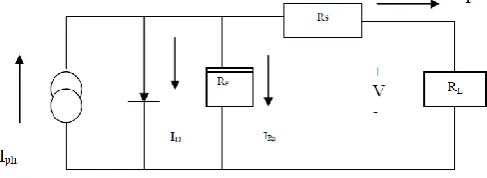
The equivalent circuit of PV cell is shown in figure 1.
Fig. 1. PV cell equivalent circuit
(1) By rearranging the following equation we get
photovoltaic current
(2)
(3) Here Iph- Insolation current
I – Cell current
Io- Reverse saturation current V- cell voltage
Rs- series resistance Rp- parallel resistance VT- Thermal voltage k- Boltzman constant T- Temperature in kelvin q- charge of electron (C)
Simulation block of solar cell and its parameters are shown in figure 2 and figure 3 respectively.
Fig. 2. Simulation block of solar cell
Fig. 3. Solar cell parameters
As one solar cell voltage is 0.5 V. Here each cell has 10 solar cells in built in it giving voltage of 5V. By connecting such 3 cells in series we will get 15V
Fig. 4. Series connection of solar cell in equivalent subsystem in matlab
Now by connecting four such subsystem in series a voltage of magnitude 60 V can be obtained as shown in figure 5.
Fig. 5. Series combination of solar subsystems
Simulation model of solar PV system can be obtained in Matlab simulation using the subsystem of solar cell which is shown in figure 6.
Fig. 6. Simulation model of solar system
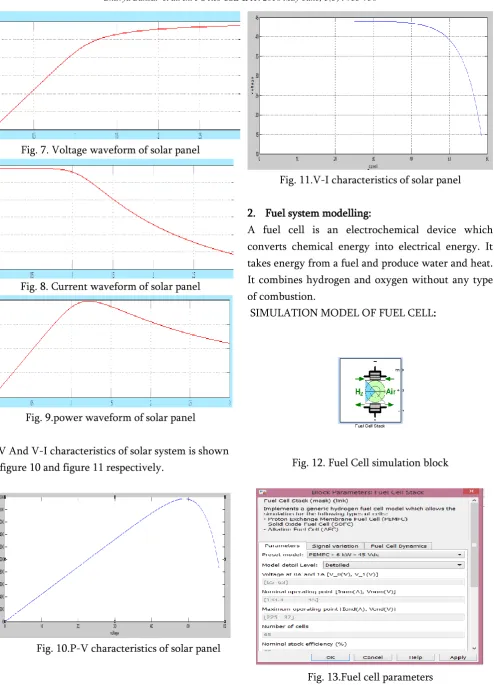
Fig. 7. Voltage waveform of solar panel
Fig. 8. Current waveform of solar panel
Fig. 9.power waveform of solar panel
P-V And V-I characteristics of solar system is shown in figure 10 and figure 11 respectively.
Fig. 10.P-V characteristics of solar panel
Fig. 11.V-I characteristics of solar panel
2. Fuel system modelling:
A fuel cell is an electrochemical device which converts chemical energy into electrical energy. It takes energy from a fuel and produce water and heat. It combines hydrogen and oxygen without any type of combustion.
SIMULATION MODEL OF FUEL CELL:
Fig. 12. Fuel Cell simulation block
3. Boost converter modelling:
It is a step up or PWM boost converter. It comprises of a Dc voltage source Vg, Boost inductor L, Diode D, a controlled switch S, Filter capacitor C and the load resistance R.
When switch S is closed (ON STATE) current starts flowing through inductor and increase linearly. Diode D is reverse biased .
When switch S is open (OFF STATE), The
Fig. 14.Internal diagram of boost converter and subsystem of boost converter
VALUES OF DIFFERENT PARAMETERS IN BOOST CONVERTER:
Inductor L 100mh
Capacitor C 100µF
Duty cycle of MOSFET 0.725
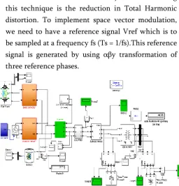
4. PWM Inverter : width modulation i.e. PWM. Major benefit of using this technique is the reduction in Total Harmonic distortion. To implement space vector modulation, we need to have a reference signal Vref which is to be sampled at a frequency fs (Ts = 1/fs).This reference signal is generated by using αβy transformation of three reference phases.
Fig. 15.MIicrogrid simulation model in island model
III.
OPTIMIZATION OF DISTRIBUTED ENEGRYSOURCES
Designing of Microgrid is a very important phase as we have to consider cost of every component used in system. So to get optimised value of power of each source we have assumed cost of each source. It can be changed depending upon market values.
As the cost of 1 KW of solar panel is between Rs. 55000 to 60000 .
Fuel cell stack cost is Rs. 10,000 per KW. Battery cost around Rs. 7600 for 1 KW .
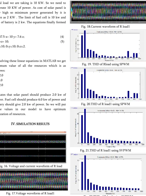
Total load we are taking is 10 KW. So we need to generate 10 KW of power. As cost of solar panel is very high so minimum power generated by it is taken as 2 KW . The limit of fuel cell is 10 kw and that of battery is 2 kw. The equations finally formed are:
C= 57.5 x+ 10 y+ 7.6 z; (4) x+y+z= 10; (5) 2≤x≤10; 0≤y≤10; 0≤z≤2. (6)
By solving these linear equations in MATLAB we get optimum value of all the resources which is as follows:
X= 2.0 Y=6.0 Z= 2.0
It states that solar panel should produce 2.0 kw of power. Fuel cell should produce 6.0 kw of power and battery should give 2.0 kw of power. So we will put these values in our model to have optimum utilization of resources.
IV.
SIMULATION RESULTSFig. 16. Voltage and current waveform of R load
Fig. 17.Voltage waveform of R load1
Fig. 18.Current waveform of R load1
Fig. 19. THD of Rload using SPWM
Fig. 20.THD of R load1 using SPWM
Fig. 21.THD of R load1 using SVPWM
V.
CONCLUSIONAs per the simulation results it can be concluded that the THD during SPWM is around 32.72% and with SVPWM it is reduces to 14.79%. So depending upon the results it is preferred to use SVPWM over SPWM for controlling of output voltage of inverter. Here Microgrid is working efficiently and feeding a load of 10 KW. Detailed study of each renewable source is shown in this paper. Further optimization of DER’S is also studied and done using MATLAB.
VI.
ACKNOWLEDGEMENTThe author would like to thanks her M.TECH supervisor Dr. Bhupal singh, HOD of Electrical engineering department, Ajay kumar garg engineering college Ghaziabad.
VII.
REFERENCES[1]. Prerna Gaur and Sunita Singh 2017 "Investigations on Issues in Microgrids", Journal of Clean Energy Technologies, Vol. 5, No. 1, January 2017
[2]. Thendral.V1, Sathish Kumar.K 2015 "Power Quality Enhancement in Grid connected Microgrid While Supplying Non-Linear Loads" International Journal for Research in Applied Science & Engineering Technology (IJRASET) [3]. Jankovic Z et al 2014 Average modeling of a
three-phase inverter for integration in a microgrid. In: Proceedings of the 2014 IEEE
Energy Conversion Congress and
Exposition(ECCE), pp. 793-799
[4]. Ohta Y et al 2013 Controller design of a grid-tie inverter bypassing DQ transformation. In: Proceedings of the 2013 IEEE 52nd Annual Conference on Decision and Control (CDC), pp. 2927-2932
[5]. Karuppaswamy A 2007 Synchronous reference
and Harmonic Current Compensation. M.Tech. Report, Calicut: NIT
[6]. Erickson R W and Maksimovic D 2007 Fundamentals of power electronics, Springer Science and Business Media, pp. 331-375 [7]. Chandorkar M C, Divan D M and Adapa R
1993 Control of parallel connected inverters in standalone AC supply systems. IEEE Trans. Ind. Appl. 29(1): 136-143
[8]. Glavin M. 2012 Optimisation of a hybrid energy storage system for autonomous photovoltaic applications [PhD Dissertation]. Galway: National University of Ireland; 2012. [9]. Parfomak P. 2012 Energy storage for power
grids and electric transportation: A technology assessment. Congressional Research Service; 2012
[10]. N Hatzaiargyriou, H. Asano, R. Iravani, C. Marnay, 2007 "Micro-grids: An overview of
ongoing research, development and
demonstration projects", IEEE Power and Energy magazine, pp. 78-94, July/August 2007. [11]. Engler A., "Applicability of Droops in Low
Voltage Grids",2004 International Journal of Distributed Energy Sources, Vol.1, number 1, pp 3-15, September 2004. [2] F. D. Kanellos, N. D. Hatziargyriou, "The effect of variable speed wind turbines on the operation of weak distribution networks," IEEE Trans.Energy Conversion, vol. 17, pp.543-548, Dec. 2002. [12]. Sun Z 2006 Switched linear systems: control
and design. Springer Science and Business Media, pp. 178-222
[13]. T.E Hoff, H.J Wenger, and B.K. Farmer,1996 "Distributed generation-An alternative to electric utility investments in system capacity", Energy Policy, 24(2):137 - 147, 1996