Calculation of the Electromagnetic Field of a Rectangular Waveguide
with Chiral Medium
Islam J. Islamov1, *, Elshad G. Ismibayli1, Mehman H. Hasanov2, Yusif G. Gaziyev1, Simnara R. Ahmadova1, and Rashid S. Abdullayev1
Abstract—A rectangular metallic waveguide with a chiral medium is considered in this article. The field distribution inside a rectangular waveguide is investigated. The task is considered in a full vector setting. The mixed finite element method is used to calculate the rectangular waveguide with a chiral medium.
1. INTRODUCTION
The intensive development of various areas of the radio-electronic industry requires the development of fundamentally new materials, strongly interacting with electromagnetic waves. Metamaterials are artificial substances whose interaction with the electromagnetic field is significantly different from the interaction of ordinary natural materials. Among the new metamaterials of particular interest are bianisotropic, biisotropic, in particular, artificial media with strong chirality [1–6].
At the same time, metamaterials find wide practical applications, for example, in building integrated optical devices and microcircuits, various waveguide systems, designing antennas and absorbing coatings with given electrodynamic properties, as well as in many other areas of radio engineering and applied electrodynamics.
Biisotropic media are the most common type of linear isotropic medium. The main difference of the biisotropic medium from the usual dielectric or magnet is the presence of a magneto-electric coupling, due to which additional terms appear in the material equations [1, 2]:
D=εE+ξH,B=ςE+μH, (1)
whereξ = (k−iχ), ς= (k+iχ).
In these expressions, εis the dielectric constant of the medium; μ is the magnetic permeability; k
is the parameter of Tellegen; χ is the parameter of chirality of the medium. The material equations are written in the frequency domain for the harmonic time dependence of the form exp(−iωt). An electric or magnetic field applied to a biisotropic medium simultaneously leads to the appearance of both electric and magnetic polarization.
An important subclass of biisotropic media is chiral media, for which k ≡ 0. Chirality is the geometric property of an object not to be combined with its mirror image. A macroscopically homogeneous material is called chiral if it consists of chiral objects, natural (molecules), or artificial.
Artificial biisotropic and bianisotropic media are created by placing metallic resonant particles (“molecules”) in a normal medium, whose dimensions are smaller than the wavelength of electromagnetic radiation in a certain range [1, 2].
Received 18 April 2019, Accepted 19 June 2019, Scheduled 3 July 2019
* Corresponding author: Islam Jamal Islamov ([email protected]).
1 Department of Electrodynamics and Radio Electronic Means, Faculty of Radio Engineering and Telecommunication, Azerbaijan
Electromagnetic field {E,H} propagating in a chiral substance splits into two independent components {E±,H±}, which behave as if they spread in ordinary non-chiral media with effective parameters ε± =ε(1±χr), μ±=μ(1±χr), whereχr=χ/√εμ. One of the waves {E±,H±} becomes the reverse wave in the case of|χr|>1 in artificial chiral media.
It should be noted that in the field of chiral insertion the field is hybrid, with the result that with a certain choice of parameters such a system can serve as a converter of one type of waves into another [7].
2. THE CURRENT STATE OF THE ISSUE
As you know, chiral media waveguides are widely used to transmit electromagnetic energy at a distance. To date, many scientific studies have been conducted on the propagation of electromagnetic fields of microwave devices with chiral media. The classical method of separation of variables solved scattering problems on a homogeneous chiral circular cylinder [8], a sphere [9], a spherical layer [10], a multi-layer circular cylinder [11], a chiral-metal cylinder [12], and an impedance sphere with a multi-layer of chiral coatings [13]. In [14], the method of surface integral equations was used to solve the problem of scattering of an electromagnetic wave on a homogeneous two-dimensional chiral cylinder of arbitrary cross section. A variant of the discrete source method is proposed for solving the problem of electromagnetic scattering on a three-dimensional homogeneous chiral body bounded by a smooth surface of an arbitrary shape [15]. In [16], this version was generalized to the case of a structure that was an ideally conducting body covered by a homogeneous chiral shell.
As can be seen from the above work, questions on the study of electromagnetic fields inside a rectangular waveguide with chiral media using the finite element method have not been studied.
Therefore, the study of electromagnetic fields inside a rectangular waveguide with chiral media using the finite element method is very new.
3. PROBLEM STATEMENT
Let us consider a rectangular waveguide with infinite ideally conducting walls located at the distancea
from each other and an inhomogeneity in the form of an insert from a chiral substance (Fig. 1). The insert is located in areaz∈[0, z0].
Figure 1. Waveguide with chiral insert.
Let the insertion material be characterized by parameters ε, μ and χ, and the waveguide filling material in the region outside the insert — by parameters ε0 and μ0.
We investigate the problem of diffraction of an electromagnetic wave incident on an insert from the region z = −∞. Suppose that the incident wave is one of the normal waveguide waves or a linear combination of them. In order to formulate a boundary value problem in region D = {x∈[0, a], z∈[0, z0]}, it is necessary to set boundary conditions at z= 0 andz=z0.
Normal waves of TE-type in the considered waveguide have the form [17–28]:
Emn,± = (iωμ0/c)
2/aexp (±iˆγnz) (πn/a) sin (πnx/a)ey, (2)
where ˆγn=k20−(πn/a)2, k02 =ε0μ0ω2/c2, n= 1,2, . . . , and the normal TM-type waves are:
Een,± = ∓iγnexp (±iγnz)2/a(πn/a) cos (πnx/a)ex+ (πn/a)22/aexp (±iγnz) cos (πnx/a)ez,(4)
Hen,± = (iωε0/c)
2/aexp (±iγnz) (πn/a) cos (πnx/a)ey, (5)
whereγn=k20(πn/a)2, n= 1,2, . . .
In regionz∈(0, z0), the electromagnetic field satisfies the Maxwell system of equations.
rotE= (iω/c)B, divD= 0,
rotH=−(iω/c)D, divB= 0 (6)
and material equations
D=εE−iχH, B=μH+iχE (7)
Since the planes bounding the waveguide are ideally conducting, the boundary conditions forx= 0 and x=aare as follows:
Ey|x=0 =Ey|x=a= 0, Ez|x=0 =Ez|x=a= 0. (8) Atz= 0 and z=z0, we use the conjugation conditions
[ez,E]|z=0 =
ez,Eext|z=0, [ez,E]z=z0 =
ez,Eextz=z0, (9)
[ez, H]|z=0 =
ez, Hext|z=0, [ez, H]z=z0 =
ez, Hextz=z0, (10)
where{Eext,Hext}is the field outside the insert.
Since in the considered problem, the exciting waveguide wave {Eins+ ,Hins+ }, which is one of the normal waves or some combination of them, falls on an insert from regionz=−∞, in the region to the left of the insert, i.e., atz <0, fieldEextis a combination of incident and reflected waves:
Eext= ∞
n=1
RmnEmn,−+RneEen,− +Eins+ , Hext= ∞
n=1
RmnHmn,−+RneHen,− +Hins+ (11)
In the area to the right of the insertion, i.e., atz > z0, theEextfield is a combination of transmitted waves:
Eext= ∞
n=1
TnmEmn,++TneEen,+ , Hext= ∞
n=1
TnmHmn,++TneHen,+ . (12)
Express the coefficients of reflection and passage through the values of the desired field E at the boundaries of the chiral insert. To do this, consider in more detail the conjugation conditions (9) at
z= 0 and z=z0:
eyEx|z=0−exEy|z=0= ∞
n=1
−exRmnEy,n,m −z=0+eyRneEx,n,e −z=0
+eyEx,ins+z=0−exEy,ins−
z=0. (13)
Comparing the right and left sides of equality (13), we obtain
Ex,ins++
∞
n=1
RenEx,n,e −
z=0
=Ex|z=0,
Ey,ins++
∞
n=1
RmnEy,n,m −
z=0
=Ex|z=0, (14)
We substitute into these equalities explicit expressions for the components of the electric field of normal waves
Ex,ins+(x,0)− ∞
n=1
Reniγn
2/a(πn/a) cos(πnx/a) = Ex(x,0), (15)
Ey,ins+(x,0) + ∞
n=1
Rmn (iωμ0/c)
From Equation (16) we get
Ren = (ia/γnπn)
2/a a
0
Ex(x,0)−Ex,ins+(x,0)
cos (πnx/a)dx, (17)
Rmn = −(ica/ωμ0πn)
2/a a
0
Ey(x,0)−Ey,ins+(x,0)
sin (πnx/a)dx. (18)
Similarly, we find the relationship of the transmission coefficients Tne and Tnm with the values of the components of field E on the boundary z =z0 of the chiral insert. Consider pairing conditions at
z=z0:
∞
n=1
TneEx,n,e +|z=z0 =Ex|z=z0 ,
∞
n=1
TnmEy,n,m +|z=z0 =Ey|z=z0 . (19)
Substituting into these equalities the explicit form of the components of the electric field of normal waves, we obtain
∞
n=1
Tneiγnexp (iγnz0)
2/a(πn/a) cos (πnx/a) = Ex(x, z0), (20)
∞
n=1
Tnm(iωμ0/c) exp (iγˆnz0)
2/a(πn/a) sin (πnx/a) = Ey(x, z0), (21)
where we find the expressions for the transmission coefficients:
Tne = −(ia/γnπn) exp (−iγnz0)
2/a a
0
Ex(x, z0) cos (πnx/a)dx, (22)
Tnm = −(ica/ωμ0πn) exp (−iˆγnz0)
2/a a
0
Ey(x, z0) sin (πnx/a)dx. (23)
It should be noted that when a plane electromagnetic wave is reflected from a chiral layer inside a rectangular waveguide, a cross-polarization (depolarization) phenomenon occurs. In a chiral medium, a plane electromagnetic wave is converted into two waves with right-round polarization and left-handed polarization, with different angles of refraction. The structure of the reflected field includes components with perpendicular (falling) and parallel (cross) polarizations. As a result, the reflected electromagnetic wave will have elliptical polarization.
It should be noted that the traveling wave mode is obtained in a line only if it is loaded with an active resistance equal to the wave one. At a different value of the load resistance in the line, a more complex process is obtained. Consider the case when the line is open at the end, that is, when the load resistance is infinitely large. Since there is no load resistance at the end of the open line, the energy of the traveling wave cannot be absorbed at the end of the line, but the wave cannot continue to move away from the generator because the line is broken. The traveling wave, having reached the end of the open line, is reflected and moves back to the generator. Thus, two traveling waves propagate in the line: one — the incident one — moves from the generator to the end of the line, and the other — reflected one — moves in the opposite direction.
Physically, the reflection process can be explained as follows. When the incident wave reaches the end of the line, charges begin to accumulate there, and consequently, an additional potential difference arises. It acts like the voltage of some generator and excites a new traveling wave in the line, moving from the end of the line to its beginning, i.e., the reflected wave.
Neglecting losses in the line, we can assume that the energy of the reflected wave is equal to the energy of the incident wave. As a result of the addition of two waves having the same amplitude and moving towards each other, so-called standing waves arise, which differ sharply from traveling waves.
4. GENERALIZED STATEMENT OF THE INITIAL TASK
of the chiral medium
rotH=−(iω/c) (εE−iχH), rotE= (iω/c) (μH+iχE). (24) Eliminating the vector Hfrom Equation (24), we get
rot1
μrotE+ ω
crot χ μE+
ω c
χ
μrotE− ω2 c2 ε−χ 2 μ
E= 0. (25)
Let us take such sufficiently smooth test functionsE∗that satisfy the boundary conditions (8). Let us multiply Equation (25) by the vector E∗ and integrate the result over the domainD:
D
E∗rot1
μrotEdS+ ω
c
D
E∗rotχ μEdS+
ω c
D
E∗χ
μrotEdS− ω2 c2 D ε−χ 2 μ
E∗EdS = 0. (26)
Let’s transform the first integral on the left side of equality (26):
D
E∗rot1
μrotEdxdz =
D 1
μrotE
∗rotEdxdz−
∂D 1
μ(n,[E
∗, rotE])dl
= z0 0 a 0 1
μrotE
∗rotEdxdz− a
0 1
μ[ez,E
∗]rotE|
z=z0dx+ a
0 1
μ[ez,E
∗]rotE|
z=0dx . (27)
Similarly transform the addend
D
E∗rotχ
μrotEdS =
D
χ μErotE
∗−
∂D
χ μ(n,[E
∗,E])dl
= z0 0 a 0 χ μErotE
∗dxdz− a
0
χ μ[ez,E
∗]·E|z
=z0 dx+ a
0
χ μ[ez,E
∗]·E|z
=0dx . (28)
So, Equation (26) takes the form z0 0 a 0 1
μrotE
∗rotEdxdz+ω
c z0 c a 0 χ μErotE
∗dxdz+ω
c z0 0 a 0 χ μE
∗rotEdxdz
−ω2
c2 z0 0 a 0 ε−χ 2 μ
E∗Edxdz−
a
0 1
μ[ez,E
∗]rotE|z=z0 z=0 +
ω cχE|
z=z0 z=0
= 0. (29)
We use the conjugation conditions (9)–(10) with z =z0 and z= 0 in order to transform the last integral in equality (29). We use Maxwell’s equations
rotE = (iω/c) (μH+iχE), z∈(0, z0), (30)
rotEext = (iω/c)μ0Hext, z∈(−∞,0)∪(z0,+∞). (31)
Multiply these equations vector by ez and rewrite them in the form
[ez,(rotE+ (ωχ/c)E)]/μ= (iω/c) [ez,H], z∈(0, z0),
ez, rotEext/μ0= (iω/c)
ez,Hext, z∈(−∞,0)∪(z0,+∞).
(32)
Using the conjugation conditions (10), from relations (32) we obtain the equality
μ0[ez,(rotE+ (ωχ/c)E)]|z=0,z0 =μ
Therefore, Equation (29) takes the form z0 0 a 0 1
μrotE
∗rotEdxdz+ω
c z0 0 a 0 χ μErotE
∗dxdz+ω
c z0 0 a 0 χ μE
∗rotEdxdz
−ω2
c2 z0 0 a 0 ε−χ 2 μ
E∗Edxdz+ a
0 1
μ0
E∗ez, rotEext
zz==0z0dx= 0. (34)
Using an explicit expression for field Eext
rotEext=
⎧ ⎪ ⎪ ⎨ ⎪ ⎪ ⎩
rotE+ins+ ∞
n=1
RenrotEen,−+RmnrotEmn,− ,
∞
n=1
TnerotEen,++TnmrotEmn,+ ,
z <0,
z > z0, (35)
we get
ez, rotEext z=0
= ey
−∂Ey,ins+
∂z −
∞
n=1
Rmn ∂E
m y,n,−
∂z
z=0 −ex
∂Ex,ins+
∂z − ∂Ez,ins+
∂x +
∞
n=1
Ren
∂Ex,n,e − ∂z −
∂Eez,n,− ∂x
z=0
= ey ⎧ ⎨ ⎩−
∂Einsy,+
∂z
z=0 +2i
a
∞
n=1 ˆ
γnsinπnx
a
a
0
Eyx,0−Ey,ins+
x,0sinπnx
a dx ⎫ ⎬ ⎭
−ex
⎧ ⎨ ⎩
∂Ex,ins+
∂z − ∂Ez,ins+
∂x
z=0 −k02
2i a ∞ n=1 1
γncos
πnx a a 0
Exx,0−Ex,ins+
x,0cosπnx a dx ⎫ ⎬ ⎭ (36) and
ez, rotEext|z=z0 = −ey ∞
n=1
Tnm∂E
m y,n,+ ∂z
z=z0
−ex
∞
n=1
Tne
∂Ex,n,e +
∂z −
∂Ez,n,e +
∂x
= −ey2i a
∞
n=1 ˆ
γnsinπnx
a
a
0
Eyx, z0
sinπnx
a dx
= exk02 2i a ∞ n=1 1
γncos
πnx a
a
0
Exx,0cosπnx
a dx
. (37)
Using equalities (36) and (37) and writing down the vectors Eand E∗ in Equation (34) by component, we obtain a generalized formulation of the problem: find a vector E ∈ H(rot, D), such that for any vector E∗∈H(rot, D),satisfying the boundary conditions (8),the equality
a 0 z0 0 1 μ
∂E∗y ∂z
∂Ey
∂z + ∂Ey∗
∂x ∂Ey
∂x + ∂Ex∗
∂z ∂E
∂z + ∂Ez∗
∂x ∂Ez
∂x − ∂Ex∗
∂z ∂Ez
∂x − ∂E∗z
∂x ∂Ex ∂z dxdz +ω c a 0 z0 0 χ μ
−∂Ey∗
∂z Ex+
∂Ex∗ ∂z −
∂Ez∗ ∂x
Ey+∂E ∗ y
∂x Ez− ∂Ey
∂z E
∗ x+Ey∗
∂Ex ∂z − ∂Ez ∂x
+Ez∗∂Ey ∂x
dxdz
−ω2
c2 a 0 z0 0 ε−χ 2 μ
E∗Edxdz−2ik
2 0
μ0a ∞ n=1 1 γn a 0
Ex∗(x, z0) cosπnx
a dx
a
0
Ex(x, z0) cosπnx
−2ik20
μ0a ∞ n=1 1 γn a 0
Ex∗(x,0) cosπnx
a dx
a
0
Ex(x,0) cosπnx
a dx
− 2i
μ0a ∞ n=1 γn a 0
Ey∗(x, z0) sinπnx
a dx
a
0
Ey(x, z0) sinπnx
a dx
− 2i
μ0a ∞ n=1 γn a 0
Ey∗(x,0) sinπnx
a dx
a
0
Ey(x,0) sinπnx
a dx
= − 1
μ0 ⎧ ⎨ ⎩ a 0
Ex∗(x,0)·
∂Exins
∂z − ∂Ezins
∂x z=0 dx+ a 0
Ey∗(x,0)∂E ins y ∂z z=0 dx ⎫ ⎬ ⎭
−2ik20
μ0a ∞ n=1 1 γn a 0
Ex∗(x,0) cosπnx
a dx
a
0
Exins(x,0) cosπnx
a dx
− 2i
μ0a ∞ n=1 γn a 0
Ey∗(x,0) sinπnx
a dx
a
0
Eyins(x,0) sinπnx
a dx. (38)
5. SOLUTION OF THE PROBLEM BY THE METHOD OF MIXED FINITE ELEMENTS
As noted in [29], when solving initial-boundary problems in regions with chiral filling, it is advisable to use projection methods. When solving waveguide problems using projection-grid methods, nonphysical solutions may appear [30, 31]. One of the ways to deal with non-physical solutions is to use such formulations of the initial problem, or such systems of basic functions, which would exclude the appearance of fictitious solutions. The approach based on the application of the mixed finite element method [32–34] is appropriate. This method was used in [35] to calculate a plane-parallel waveguide with a non-chiral insert. Since it turned out to be very effective, it was chosen to calculate the chiral waveguide under consideration.
We introduce in the waveguide region in the plane Oxz a rectangular grid: zj = j ·Δz, j = 0, J , xi =i·Δx, i= 0, I. Select the basic functions of the following form:
Ni(ξ) =
⎧ ⎨ ⎩
(ξi+1−ξ)/(ξi+1−ξi), (ξ−ξi−1)/(ξi−ξi−1),
0, ξ ∈(−∞, ξi−1)∪(ξi+1,+∞),
Pi,i+1(ξ) =
1, ξ ∈[ξi, ξi+1],
0, ξ ∈(−∞, ξi)∪(ξi+1),+∞
(39)
We will look for an approximate solution of problem (38) as an expansion in basis functionsNi(ξ)
and Pi,i+1(ξ): ⎧
⎪ ⎪ ⎪ ⎪ ⎪ ⎪ ⎪ ⎪ ⎪ ⎪ ⎪ ⎨ ⎪ ⎪ ⎪ ⎪ ⎪ ⎪ ⎪ ⎪ ⎪ ⎪ ⎪ ⎩
Ex(x, z) = I−1
i=0 J
j=0
Exi,jNj(z)Pi,i+1(x),
Ey(x, z) = I−1
i=1 J
j=0
Eyi,jNj(z)Ni(x),
Ez(x, z) = I−1
i=1 J−1
j=0
Ezi,jPj,j+1(z)Ni(x).
(40)
take the values
1) E∗(x, z) = {Nj(z)Pi,i+1(x)}ex, i= 0,(I−1), j= 0, J; (41)
2) E∗(x, z) = {Nj(z)Ni(x)}ey, i= 1,(I−1), j = 0, J; (42)
3) E∗(x, z) = {Pi,i+1(z)Nj(x)}ez, i= 1,(I−1), j= 0,(J−1). (43)
Imagine the desired vector of field values in grid nodes in the form
ψ=
⎧ ⎪ ⎪ ⎨ ⎪ ⎪ ⎩
Exi,0 !
i=0,(I−1)
,Exi,1, . . . ,Ei,Jx ;Eyi,0, Eyi,1 !
i=1,(I−1)
, . . . ,Eyi,J; Ezi,0 !
i=1,(I−1)
,Ezi,1, . . . ,Ezi,J−1 ⎫ ⎪ ⎪ ⎬ ⎪ ⎪ ⎭
T
. (44)
Then the system of equations for finding coefficients can be written in matrix form
Aψ=F, (45)
whereFis the column of the right parts, which is determined by the parameters of the electric component
Eins(x, z), incident on the wave insert.
(a) (b)
(c)
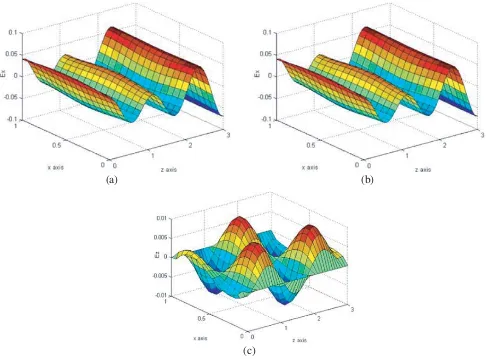
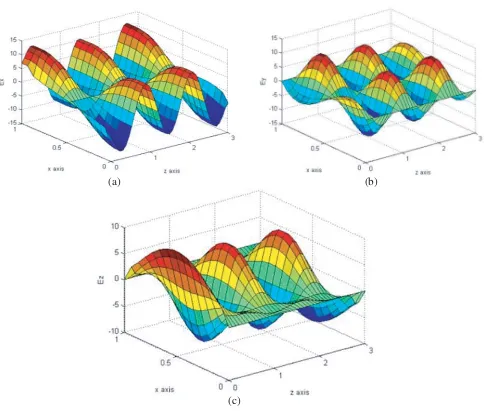
Figure 2. Field components inside the insert in case χ= 0.01: Ex-field is (a), Ey-field is (b) andEz
6. RESULTS OF NUMERICAL SIMULATION
Testing of the proposed algorithm was carried out on a dielectric-filled waveguide. Then, a series of calculations of the field inside the insert with a nonzero chirality parameter was performed.
In the case when the incident wave is the main (n0 = 1) wave of the TE-type
E+ins=
0, Einsy,+,0 , Ey,ins+(x, z) =A0exp (iγˆn0z) sin (πn0x/a) (46) with a frequency ofω/c= 5, and all the parameters of the waveguide, except the chirality parameterχ, are unchanged and have the forma= 1, z0 = 3, ε0 =μ0= 1. The results in Figs. 2–6 were obtained.
(a) (b)
(c)
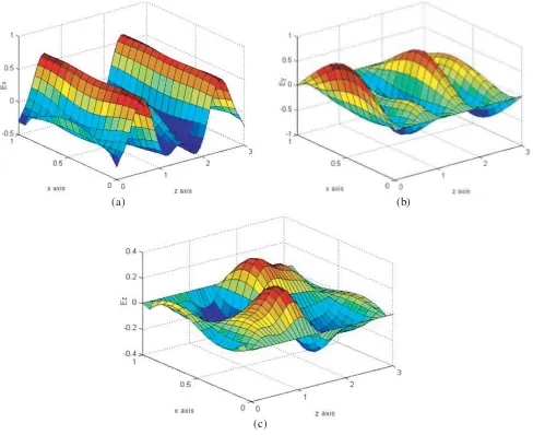
Figure 3. Field components inside the insert in caseχ= 0.5: Ex-field is (a), Ey-field is (b) and Ezis (c).
Figs. 3 and 4 show the results of calculating the components of the electric field inside the insert for the values of the chirality parameter approaching the critical valueχc =√εμ(in the considered case
χc = 1).
As long as the chirality parameter remains below the critical value, the wave fields in the medium with equivalent parameters ε±,μ± remain direct waves, since they areε±>0 andμ± >0. The result of the interference of these waves can be seen in Figs. 3 and 4.
(a) (b)
(c)
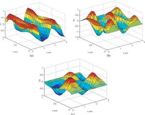
Figure 4. Field components inside the insert in caseχ= 0.8: Ex-field is (a), Ey-field is (b) and Ezis (c).
(c)
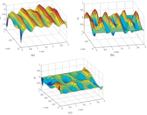
Figure 5. Field components inside the insert in case χ= 1.01: Ex-field is (a), Ey-field is (b) andEz
is (c).
(a) (b)
(c)
In the case when the incident wave is the main TM-type wave:
Eins+ = Ex,ins+,0, Ez,ins+ , (47)
Ex,ins+(x, z) = ˜A0iγn0(πn0/a) exp (iγn0z), (48)
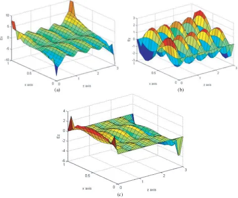
Ez,ins+(x, z) = ˜A0(πn0/a)2exp (iγn0z) sin (πn0x/a) (49) with a frequency ofω/c= 5, and all the parameters of the waveguide, except the chirality parameterχ, are unchanged and have the forma= 1, z0 = 3, ε0 =μ0= 1. The results in Figs. 7–11 were obtained.
(a) (b)
(c)
Figure 7. Field components inside the insert in case χ= 0.01: Ex-field is (a), Ey-field is (b) andEz
is (c).
In the case of a sufficiently small chirality parameter χ= 0.01, the components Ex and Ez of the electric field inside the insert vary slightly compared with the corresponding components of the field in the empty waveguide. In this case, due to the magneto-electric coupling, a non-zero component of the electric field Ey appears.
Figs. 8 and 9 show the results of calculating the components of the electric field inside the insert for the values of the chirality parameter approaching the critical value χc =√εμ.
(a) (b)
(c)
Figure 8. Field components inside the insert in caseχ= 0.5: Ex-field is (a), Ey-field is (b) and Ezis (c).
a direct wave in an equivalent medium with parameters ε+, μ+, and a reverse wave in an equivalent medium with parameters ε−,μ−.
7. DISCUSSION OF THE OBTAINED NUMERICAL RESULTS
(a) (b)
(c)
Figure 9. Field components inside the insert in caseχ= 0.8: Ex-field is (a), Ey-field is (b) and Ezis (c).
(c)
Figure 10. Field components inside the insert in case χ= 1.01: Ex-field is (a),Ey-field is (b) andEz
is (c).
(a) (b)
(c)
Figure 11. Field components inside the insert in case χ= 1.1: Ex-field is (a),Ey-field is (b) andEz
the cutoff frequency of the main mode, there are a couple of modes, called bifurcated, with different propagation constants and the same cutoff frequency. Thus, we obtain two values of the propagation constant for a fixed frequency.
8. CONCLUSION
The paper proposes an algorithm for calculating a flat electromagnetic shielded waveguide with chiral insertion by the method of mixed finite elements, which prevents the appearance of non-physical solutions in electromagnetic problems. Studies show that the method of mixed finite elements is very effective for the numerical solution of mathematical models of wave-guiding systems with chiral filling. It is shown that in the field of chiral insertion the field is hybrid, with the result that with a certain choice of parameters such a system can serve as a transducer of one type of wave to another.
The developed algorithm can be fairly easily generalized to the case of biisotropic and bianisotropic filling, as well as to the case of three-dimensional waveguides of arbitrary cross section.
A program built on the basis of the proposed method can be used as a program module for solving a direct problem in a general program for solving an inverse problem of synthesizing a waveguide system with a complex filling that has specified technical characteristics.
Thus, the developed numerical and mathematical method allows to solve problems of modeling complex biisotropic and bianisotropic materials, which contributes to their use in the development and study of new devices and systems that have wide practical application.
REFERENCES
1. Shcherbinin, V. I., B. A. Kochetov, A. V. Hlushchenko, and V. I. Tkachenko, “Cutoff frequencies of a dielectric-loaded rectangular waveguide with arbitrary anisotropic surface impedance,” IEEE Transactions on Microwave Theory and Techniques, Vol. 67, No. 2, 577–583, 2019.
2. Kesari, V. and J. P. Keshari, “Hybrid-mode analysis of circular waveguide with chiral dielectric lining for dispersion characteristics for potential application in broadbanding a gyro-traveling-wave tube,”Journal of Electromagnetic Waves and Applications, Vol. 33, No. 2, 204–214, 2019.
3. Ji, Z. Q., K. X. Wang, and H. Wong, “Circularly polarized dielectric rod waveguide antenna for millimeter-wave applications,” IEEE Transactions on Antennas and Propagation, Vol. 66, No. 10, 5080–5087, 2018.
4. Meyer, A., K. Kruger, and M. Schneider, “Dispersion-minimized rod and tube dielectric waveguides at w-band and d-band frequencies,” IEEE Microwave and Wireless Components Letters, Vol. 28, No. 7, 555–557, 2018.
5. Shestopalov, Y. and E. Kuzmina, “Symmetric surface waves along a metamaterial dielectric waveguide and a perfectly conducting cylinder covered by a metamaterial layer,” Advanced Electromagnetics, Vol. 7, No. 2, 91–98, 2018.
6. Bachiller, C., H. Esteban, F. Diaz, J. V. Morro, and V. E. Boria, “Radio-frequency performance comparison of several H-plane rectangular waveguide filters loaded with circular dielectric posts,”
IET Microwaves Antennas &Propagation, Vol. 10, No. 5, 536–545, 2016.
7. Freirea, M. J., R. Marqu´es, and F. Medina, “Planar magnetoinductive wave transducers: Theory and applications,” Appl. Phys. Lett., Vol. 85, 4439, 2004.
8. Bohren, C. F., “Scattering of electromagnetic waves by an optically active cylinder,”Journal Colloid Interface Science, Vol. 66, No. 1, 105–109, 1978.
9. Bohren, C. F., “Light scattering by an optically active sphere,”Chem. Phys. Letters, Vol. 29, No. 3, 458–462, 1974.
10. Bohren, C. F., “Scattering of electromagnetic waves by an optically active spherical shell,”Journal Chem. Phys., No. 4, 1556–1571, 1975.
12. Neganov, V. A. and O. V. Osipov, “Scattering of plane electromagnetic waves by the chiral-metal cylinder,”Letters to the Journal of Technical Physics, Vol. 26, No. 1, 77–83, 2000 (in Russian). 13. Uslenghi, P. L. E., “Scattering by an impedance sphere coated with a chiral layer,”
Electromagnetics, Vol. 10, No. 2, 201–211, 1990.
14. Fedorenko, A. I., “Solution of the problem of electromagnetic wave scattering on a homogeneous chiral cylinder using the method of surface integral equations,”Radio Engineering and Electronics, Vol. 40, No. 3, 381–393, 1995 (in Russian).
15. Dmitrenko, A. G., A. I. Mukomolov, and V. V. Fisanov, “A numerical method for solving problems of electromagnetic scattering on a three-dimensional chiral body,” Radio Engineering and Electronics, Vol. 43, No. 8, 910–914, 1998 (in Russian).
16. Dmitrenko, A. G. and S. V. Korogodov, “The scattering of electromagnetic waves on an ideally conducting body in a chiral shell,” News of Universities. Radio Physics, Vol. 41, No. 4, 495–506, 1998 (in Russian).
17. Zhao, J.-S. and W. C. Chew, “Integral equation solution of Maxwell’s equations from zero frequency to microwave frequencies,”IEEE Transactions on Antennas and Propagation, Vol. 48, No. 10, 1635– 1645, 2000.
18. Chew, W. C., M. S. Tong, and B. Hu, “Integral equation methods for electromagnetic and elastic waves,” Journal Synthesis Lectures on Computational Electromagnetics, Vol. 3, No. 1, 1–241, 2008. 19. He, B., C. Lu, N. N. Chen, D. S. Lin, M. Rosu, and P. Zhou, “Time decomposition method for the general transient simulation of low-frequency electromagnetics,” Progress In Electromagnetics Research, Vol. 160, 1–8, 2017.
20. Islamov, I. J., E. G. Ismibayli, M. H. Hasanov, Y. G. Gaziyev, and R. S. Abdullayev, “Electrodynamics characteristics of the no resonant system of transverse slits located in the wide wall of a rectangular waveguide,” Progress In Electromagnetics Research, Vol. 80, 23–29, 2018. 21. Islamov, I. J., E. G. Ismibayli, Y. G. Gaziyev, S. R. Ahmadova, and R. Sh. Abdullayev, “Modeling of
the electromagnetic field of a rectangular waveguide with side holes,”Progress In Electromagnetics Research, Vol. 81, 127–132, 2019.
22. Chen, S. C. and W. C. Chew, “Electromagnetic theory with discrete exterior calculus,” Progress In Electromagnetics Research, Vol. 159, 59–78, 2017.
23. Lindell, I. V., “Plane-wave propagation in electromagnetic PQ medium,” Progress In Electromagnetics Research, Vol. 154, 23–33, 2015.
24. He, S., F. Sun, S. Guo, S. Zhong, L. Lan, W. Jiang, Y. Ma, and T. Wu, “Can Maxwell’s fish eye lens really give perfect imaging? Part III. A careful reconsideration of the evidence for subwavelength imaging with positive refraction,”Progress In Electromagnetics Research, Vol. 152, 1–15, 2015. 25. He, Y., H. Qin, Y. J. Sun, J. Y. Xiao, R. L. Zhang, and J. Liu, “Hamiltonian time integrators for
Vlasov-Maxwell equations,”Physics of Plasmas, Vol. 22, No. 12, 124503–4, 2015.
26. Epstein, C. L., L. Greengard, and M. O’Neil, “Debye sources, Beltrami fields, and a complex structure on Maxwell fields,”Communications on Pure and Applied Mathematics, Vol. 68, No. 12, 2237–2280, 2015.
27. Stratis, I. G. and A. N. Yannacopoulos, “Some remarks on a class of inverse problems related to the parabolic approximation to the Maxwell equations: A controllability approach,” Mathematical Methods in the Applied Sciences, Vol. 38, No. 17, 3866–3878, 2015.
28. Hess, M. W., S. Grundel, and P. Benner, “Estimating the inf-sup constant in reduced basis methods for time-harmonic Maxwell’s equations,”IEEE Transactions on Microwave Theory and Techniques, Vol. 63, No. 11, 3549–3557, 2015.
29. Balbastre, J. V. and L. Nuno, “Modelling the propagation of electromagnetic waves across complex metamaterials in closed structures,” Journal of computational and Applied Mathematics, Vol. 352, 40–49, 2018.
of Neural Engineering, Vol. 16, No. 2, 024001, 2019.
31. Tsuburaya, T., Y. Okamoto, and S. Sato, “Fast computation of linear systems based on parallelized preconditioned MRTR method supported by block-multicolor ordering in electromagnetic field analysis using edge-based finite element method,” Electronics and Communications in Japan, Vol. 100, No. 8, 59–70, 2017.
32. Ciarlet, P., S. Fliss, and C. Stohrer, “On the approximation of electromagnetic fields by edge finite elements. Part 2: A heterogeneous multiscale method for Maxwell’s equations,” Computers
& Mathematics with Applications, Vol. 73, No. 9, 1900–1919, 2017.
33. Kurachka, K. S., “Numerical modeling of a influence of a nanoparticle pair on the electromagnetic field in the near zone by the vector finite elements method,” Computer Optics, Vol. 42, No. 4, 542–549, 2018.
34. Shi, D. Y., M. H. Li, and Z. Z. Li, “A nonconforming finite element method for the stationary Smagorinsky model,” Applied Mathematics and Computation, Vol. 353, 308–319, 2018.