Available online: https://edupediapublications.org/journals/index.php/IJR/ P a g e | 1147
Performance Evaluation of Artificial Intelligence Controller for
Brushless DC Motor Driven household refrigerator Compressor
P. GunaSakhar & S. Munisekhar
1PG Student, Dept of EEE, Siddhartha Institute of Engineering & Technology, Puttur. 2Associate Professor, Dept of EEE, Siddhartha Institute of Engineering & Technology, Puttur.
1[email protected],2m[email protected] Abstract: Household refrigerator is a daily-need
home electrical device and operates practically all the year. In household refrigerator compressor applications, Brushless DC motors (BLDCM) are most predominantly used. Here, an artificial intelligence controller is used for effective speed regulation of BLDCM. In general, artificial intelligence controllers (AIC) provide better transient performance and results steady state error. The PI speed controller gives good steady state performance but poor transient performance. For getting an efficient performance, the referred artificial intelligence PI controller combines the merits of the above two controllers. Also, this paper presents relative study among PI, AIC and hybrid fuzzy PI controller for a BLDCM. In Matlab/Simulink environment, the BLDCM with proposed controller is designed and simulated. Results prove the predominance of proposed artificial intelligence PI controller for BLDC motors.
Keyword: Brushless DC motor (BLDCM), Artificial intelligence Controller (AIC), PI Controller (PI), Hysteresis Current Controller (HCC).
I. INTRODUCTION
EFFICIENCY and cost are the major concerns in the development of low-power motor drives targeting household applications such as fans, water pumps, blowers, mixers, etc. [1], [2]. The use of the brushless direct current (BLDC) motor in these applications is becoming very common due to features of high efficiency,
high flux density per unit volume, low maintenance requirements, and low electromagnetic-interference problems [1]. These BLDC motors are not limited to household applications, but these are suitable for other applications such as medical equipment, transportation, HVAC, motion control, and many industrial tools [2]–[4]. A BLDC motor has three phase windings on the stator and permanent magnets on the rotor [5], [6]. The BLDC motor is also known as an electronically commutated motor because an electronic commutation based on rotor position is used rather than a mechanical commutation which has disadvantages like sparking and wear and tear of brushes and commentatorassembly [5].
Available online: https://edupediapublications.org/journals/index.php/IJR/ P a g e | 1148 the literaturewhich has gained importance
because of high efficiency ascompared to two-stage PFC converters due to low componentcount and a single switch for dc link voltage control and PFC
Operation [9], [10].
The choice of mode of operation of a PFC converter is acritical issue because it directly affects the cost and rating ofthe components used in the PFC converter. The continuousconduction mode (CCM) and discontinuous conduction mode(DCM) are the two modes of operation in which a PFC converteris designed to operate [9], [10]. In CCM, the current inthe inductor or the voltage across the intermediate capacitorremains continuous, but it requires the sensing of two voltages(dc link voltage and supply voltage) and input side currentfor PFC operation, which is not cost-effective. On the otherhand, DCM requires a single voltage sensor for dc link voltagecontrol, and inherent PFC is achieved at the ac mains, but atthe cost of higher stresses on the PFC converter switch; hence,DCM is preferred for low-power applications [9], [10].
The conventional PFC scheme of the BLDC motordrive utilizes a pulse width-modulated voltage source inverter(PWM-VSI) for speed control with a constant dc link voltage.This offers higher switching losses in VSI as the switchinglosses increase as a square function of switching frequency. Asthe speed of the BLDC motor is directly proportional to theapplied dc link voltage, hence, the speed control is achieved bythe variable dc link voltage of VSI. This allows the fundamentalfrequency switching of VSI (i.e., electronic commutation) andoffers reduced switching losses.Singh and Singh [11] have proposed a buck–boost converterfeeding a BLDC motor based on the concept of constantdc link voltage and PWM-VSI for speed control
which hashigh switching losses. A single-ended primary-inductance converter(SEPIC)-based BLDC motor drive has been proposed byFor further improvement in efficiency, bridgeless (BL) convertersare used which allow the elimination of DBR in the frontend [13]–[21]. A buck–boost converter configuration is bestsuited among various BL converter topologies for applicationsrequiring a wide range of dc link voltage control (i.e., buckingand boosting mode). Jang and Jovanovich [13] and Huber et al.[14] have presented BL buck and boost converters, respectively.
These can provide the voltage buck [13] or voltage boost [14],[15] which limits the operating range of dc link voltage control.Wei et al. [16] have proposed a BL buck–boost converterbut use three switches which is not a cost-effective solution.A new family of BL SEPIC and Cuk converters has beenreported in the literature [17]–[21] but requires a large numberof components and has losses associated with it.
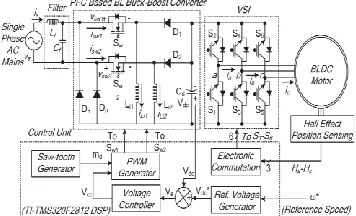
This paper presents a Fuzzy based PFC - BL buck–boost converter-fed BLDCmotor drive with variable dc link voltage of VSI for improvedpower quality at ac mains with reduced components.
Fig. 1. Proposed BLDC motor drive with front-end BL buck–boost converter.
Available online: https://edupediapublications.org/journals/index.php/IJR/ P a g e | 1149 Fig. 1 shows the proposed BL buck–
boost converter-basedVSI-fed BLDC motor drives. The parameters of the BLbuck–boost converter are designed such that it operates indiscontinuous inductor current mode (DICM) to achieve aninherent power factor correction at ac mains. The speed control
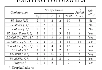
TABLE I
COMPARATIVE ANALYSIS OF PROPOSED BL BUCK–BOOST CONVERTERWITH
EXISTING TOPOLOGIES
of BLDC motor is achieved by the dc link voltage control of VSI using a BL buck–boost converter. This reduces the switching losses in VSI due to the low frequency operation of VSI for the electronic commutation of the BLDC motor.
The performance of the proposed drive is evaluated for a wide range of speed control with improved power quality at ac mains. Moreover, the effect of supply voltage variation at universal ac mains is also studied to demonstrate the performance of the drive in practical supply conditions. Voltage and current stresses on the PFC converter switch are also evaluated for determining the switch rating and heat sink design. Finally, a hardware implementation of the proposed BLDC motor drive is carried out to demonstrate the feasibility of the proposed drive over a wide range of speed control with improved power quality at ac mains.
A brief comparison of various configurations reported in the literature is
tabulated in Table I. The comparison is carried out on the basis of the total number of components (switch—Sw, diode—D, inductor— L, and capacitor—C) and total number of components conducting during each half cycle of supply voltage. The BL buck [13] and boost [14], [15] converter configurations are not suitable for the required application due to the requirement of high voltage conversion ratio. The proposed configuration of the BL buck– boost converter has the minimum number of components and least number of conduction devices during each half cycle of supply voltage which governs the choice of the BL buck–boost converter for this application.
III. OPERATING PRINCIPLE OF PFC BL BUCK–BOOST CONVERTER
The operation of the PFC BL buck– boost converter is classified into two parts which include the operation during the positive and negative half cycles of supply voltage and during the complete switching cycle.
A. Operation during Positive and Negative Half Cycles of Supply Voltage
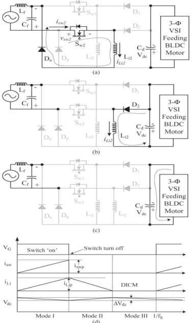
In the proposed scheme of the BL buck– boost converter, switches Sw1 and Sw2 operate for the positive and negative half cycles of the supply voltage, respectively. During the positive half cycle of the supply voltage, switch Sw1, inductor Li1, and diodes D1 and Dpare operated to transfer energy to dc link capacitor Cd as shown in Fig. 2(a)–(c). Similarly, for the negative half cycle of the supply voltage, switch Sw2, inductor Li2, and diodes D2 and Dnconduct as shown in Fig. 3(a)–(c). In the DICM operation of the BL buck–boost converter, the current in inductor Li becomes discontinuous for certain duration in a switching period. Fig. 2(d) shows the waveforms of different parameters during the positive and negative half cycles of supply voltage.
Available online: https://edupediapublications.org/journals/index.php/IJR/ P a g e | 1150 Three modes of operation during a
complete switching cycle are discussed for the positive half cycle of supply voltage as shown hereinafter.
Mode I: In this mode, switch Sw1 conducts to charge the inductor Li1; hence, an inductor current iLi1 increases in this mode as shown in Fig. 2(a). Diode Dpcompletes the input side circuitry, whereas the dc link capacitor Cd is discharged by the VSI-fed BLDC motor as shown in Fig. 3(d).
Fig. 2. Operation of the proposed converter in different modes (a)–(c) for a positive half cycles
of supply voltage and (d) the associated waveforms. (a) Mode I. (b) Mode II. (c) Mode III. (d) Waveforms for positive and negative half
cycles of supply voltage.
Mode II: As shown in Fig. 2(b), in this mode of
operation, switch Sw1 is turned off, and the stored energy in inductor Li1 is transferred to dc link capacitor Cd until the inductor is completely discharged. The current in inductor Li1 reduces and reaches zero as shown in Fig. 3(d).
Mode III: In this mode, inductor Li1 enters
discontinuous conduction, i.e., no energy is left in the inductor; hence, current iLi1 becomes zero for the rest of the switching period. As shown in Fig. 2(c), none of the switch or diode is conducting in this mode, and dc link capacitor Cd supplies energy to the load; hence, voltage Vdc across dc link capacitor Cd starts decreasing. The operation is repeated when switch Sw1 is turned on again after a complete switching cycle.
Similarly, for the negative half cycle of the supply voltage, switch Sw2, inductor Li2, and diodes Dnand D2 operate for voltage control and PFC operation.
IV. DESIGN OF PFC BL BUCK–BOOST CONVERTER
Available online: https://edupediapublications.org/journals/index.php/IJR/ P a g e | 1151 The relation governing the voltage conversion
ratio for a buck–boost converter is given as [22]
Fig. 3. Operation of the proposed converter in different modes (a)–(c) for a negative half cycles of supply voltage and (d) the associated waveforms. (a)Mode I. (b) Mode II. (c)Mode III. (d)Waveforms during complete switching cycle.
Fig. 4. Supply current at the rated load on BLDC motor for different values of input side inductors with supply voltage as 220 V and dc link voltage as 50 V.
The proposed converter is designed for dc link voltage control from 50 V (Vdc min) to 200 V (Vdcmax) with a nominal value (Vdc des) of 100 V; hence, the minimum and the maximum duty ratio (dmin and dmax) corresponding to Vdc min and Vdcmax are calculated as 0.2016 and 0.5025, respectively. Design of Input Inductors (Li1 and Li2)
The value of inductance Lic1, to operate in critical conduction mode in the buck–boost converter, is given as [23]
whereR is the equivalent load resistance, d is the duty ratio, and fsis the switching frequency. Now, the value of Lic1 is calculated at the worst
duty ratio of dmin such that the converter operates in DICM even at very low duty ratio. At minimum duty ratio, i.e., the BLDC motor operating at 50 V (Vdc min), the power (Pmin)
is given as 90 W (i.e., for constant torque, the load power is proportional to speed). Hence,
Available online: https://edupediapublications.org/journals/index.php/IJR/ P a g e | 1152 The values of inductances Li1 and Li2 are taken
less than 1/10th of the minimum critical value of inductance to ensure a deep DICM condition [24]. The analysis of supply current at minimum duty ratio (i.e., supply voltage as 220 V and dc link voltage as 50 V) is carried out for different values of the inductor (Li1 and Li2). Fig. 4 shows the supply current at the input inductor’s value as Lic, Lic/2, Lic/5, and Lic/10, respectively. The supply current at higher values of the input side inductor is highly distorted due to the inability of the converter to operate in DICM at peak values of supply voltages.
Hence, the values of inductors Li1 and Li2 are selected around 1/10th of the critical inductance and are taken as 35 μH. It reduces the size, cost, and weight of the PFC converter.
V. Fuzzy controller
Fuzzy logic uses fuzzy set theory, in which a variable is member of one or more sets, with a specified degree of membership. Fuzzy logic allow us to emulate the human reasoning process in computers, quantify imprecise information, make decision based on vague and in complete data, yet by applying a “defuzzification” process, arrive at definite conclusions.
The FLC mainly consists of three blocks
Fuzzification
Inference
Defuzzification RULES:
If input is NEGATIVE then output is POSITIVE
If input is ZERO then output is ZERO If input is POSITIVE then output is NEGATIVE
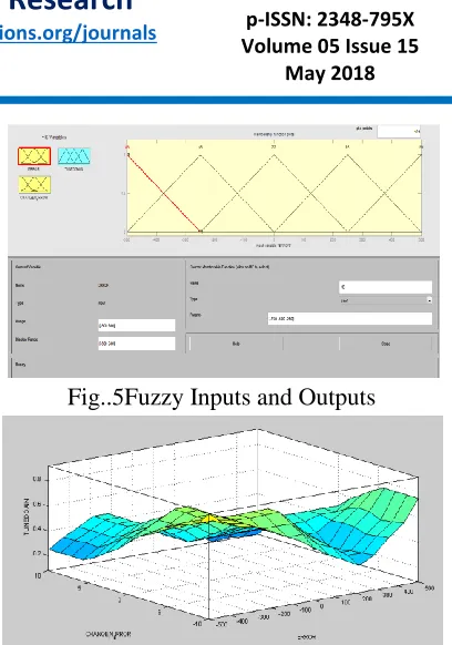
Fig..5Fuzzy Inputs and Outputs
Figure 6 Surface of the Fuzzy logic controller
VI.SIMULATED PERFORMANCE OF PROPOSED BLDC MOTOR DRIVE
The performance of the proposed BLDC motor drive is simulated in MATLAB/Simulink environment using the Sim- Power-System toolbox. The performance evaluation of the proposed drive is categorized in terms of the performance of the BLDC motor and BL buck– boost converter and the achieved
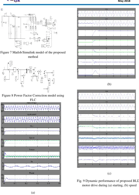
Available online: https://edupediapublications.org/journals/index.php/IJR/ P a g e | 1153 Figure 7 Matlsb/Simulink model of the proposed
method
Figure 8 Power Factor Correction model using FLC
(a)
(b)
(c)
Available online: https://edupediapublications.org/journals/index.php/IJR/ P a g e | 1154 control, and (c) supply voltage variation at rated
conditions.
Fig.10 % of the Total Harmonic Distortion of Input current
VII CONCLUSION
A PFC BL buck–boost converter-based VSI-fed BLDC motor drive has been proposed targeting low-power applications. A new method of speed control has been utilized by controlling the voltage at dc bus and operating the VSI at fundamental frequency for the electronic commutation of the BLDC motor for reducing the switching losses in VSI. The front-end BL buck–boost converter has been operated in DICM for achieving an inherent power factor correction at ac mains. A satisfactory performance has been achieved for speed control and supply voltage variation with power quality indices within the acceptable limits of IEC 61000-3-2. Moreover, voltage and current stresses on the fuzzy based PFC switch have been evaluated for determining the practical application of the proposed scheme. Finally, an experimental prototype of the proposed drive has been developed to validate the performance of the proposed BLDC motor drive under speed control with improved power quality at ac mains. The proposed scheme has shown satisfactory performance, and it is a recommended solution applicable to low-power BLDC motor drives.
REFERENCES
[1] C. L. Xia, Permanent Magnet Brushless DC
Motor Drives and Controls. Hoboken, NJ, USA:
Wiley, 2012.
[2] J. Moreno, M. E. Ortuzar, and J. W. Dixon, “Energy-management system for a hybrid electric vehicle, using ultracapacitors and neural networks,” IEEE Trans. Ind. Electron., vol. 53, no. 2, pp. 614– 623, Apr. 2006.
[3] Y. Chen, C. Chiu, Y. Jhang, Z. Tang, and R. Liang, “A driver for the singlephase brushless dc fan motor with hybrid winding structure,” IEEE Trans.Ind. Electron., vol. 60, no. 10, pp. 4369–4375, Oct. 2013.
[4] X. Huang, A. Goodman, C. Gerada, Y. Fang, and Q. Lu, “A single sided matrix converter drive for a brushless dc motor in aerospace applications,” IEEE Trans. Ind. Electron., vol. 59, no. 9, pp. 3542–3552, Sep. 2012.
[5] H. A. Toliyat and S. Campbell, DSP-Based
Electromechanical Motion Control. Boca Raton, FL,
USA: CRC Press, 2004.
[6] P. Pillay and R. Krishnan, “Modeling of permanent magnet motor drives,” IEEE Trans. Ind. Electron., vol. 35, no. 4, pp. 537–541, Nov. 1988.
[7] Limits for Harmonic Current Emissions
(Equipment Input Current ≤16 A Per Phase), Int. Std. IEC 61000-3-2, 2000.
[8] S. Singh and B. Singh, “A voltage-controlled PFC Cuk converter based PMBLDCM drive for air-conditioners,” IEEE Trans. Ind. Appl., vol. 48, no. 2, pp. 832–838, Mar./Apr. 2012.
[9] B. Singh, B. N. Singh, A. Chandra, K. Al-Haddad, A. Pandey, and D. P. Kothari, “A review of single-phase improved power quality acdc converters,” IEEE Trans. Ind. Electron., vol. 50, no. 5, pp. 962–981, Oct. 2003.
[10] B. Singh, S. Singh, A. Chandra, and K. Al-Haddad, “Comprehensive study of single-phase ac-dc power factor corrected converters with high-frequency isolation,” IEEE Trans. Ind. Informat., vol. 7, no. 4,
pp. 540–556, Nov. 2011.
Available online: https://edupediapublications.org/journals/index.php/IJR/ P a g e | 1155 with reduced sensor buck-boost PFC converter,” in
Proc. 4th ICETET, Nov. 18–20, 2011, pp. 180–184.
[12] T. Gopalarathnam and H. A. Toliyat, “A new topology for unipolar brushless dc motor drive with high power factor,” IEEE Trans. Power Electron., vol. 18, no. 6, pp. 1397–1404, Nov. 2003.
[13] Y. Jang and M. M. Jovanovi´c, “Bridgeless high-power-factor buck converter,” IEEE Trans. Power Electron., vol. 26, no. 2, pp. 602–611, Feb. 2011.
[14] L. Huber, Y. Jang, and M. M. Jovanovi´c, “Performance evaluation of bridgeless PFC boost rectifiers,” IEEE Trans. Power Electron., vol. 23, no. 3, pp. 1381–1390, May 2008.
[15] A. A. Fardoun, E. H. Ismail, M. A. Al-Saffar, and A. J. Sabzali, “New ‘real’ bridgeless high efficiency ac-dc converter,” in Proc. 27th Annu.IEEE
APEC Expo., Feb. 5–9, 2012, pp. 317–323.
[16] W. Wei, L. Hongpeng, J. Shigong, and X. Dianguo, “A novel bridgeless buck-boost PFC converter,” in IEEE PESC/IEEE Power Electron. Spec.Conf., Jun. 15–19, 2008, pp. 1304–1308. [17] A. A. Fardoun, E. H. Ismail, A. J. Sabzali, and M. A. Al-Saffar, “New efficient bridgeless Cuk rectifiers for PFC applications,” IEEE Trans.Power Electron., vol. 27, no. 7, pp. 3292–3301, Jul. 2012. [18] A. A. Fardoun, E. H. Ismail, A. J. Sabzali, and M. A. Al-Saffar, “A comparison between three proposed bridgeless Cuk rectifiers and conventional topology for power factor correction,” in Proc. IEEE ICSET, Dec. 6–9, 2010, pp. 1–6.
[19] M. Mahdavi and H. Farzaneh-Fard, “Bridgeless CUK power factor correction rectifier with reduced conduction losses,” IET Power Electron., vol. 5, no. 9, pp. 1733–1740, Nov. 2012.
[20] A. J. Sabzali, E. H. Ismail, M. A. Al-Saffar, and A. A. Fardoun, “New
bridgeless DCM Sepic and Cuk PFC rectifiers with low conduction and switching losses,” IEEE Trans. Ind. Appl., vol. 47, no. 2, pp. 873–881, Mar./Apr. 2011.
[21] M. Mahdavi and H. Farzanehfard, “Bridgeless SEPIC PFC rectifier with reduced components and conduction losses,” IEEE Trans. Ind. Electron., vol. 58, no. 9, pp. 4153–4160, Sep. 2011.
[22] N. Mohan, T. M. Undeland, and W. P. Robbins, Power Electronics: Converters, Applications and
Design. Hoboken, NJ, USA: Wiley, 2003.
[23] A. Emadi, A. Khaligh, Z. Nie, and Y. J. Lee, Integrated Power Electronic Converters and Digital
Control. Boca Raton, FL, USA: CRC Press,2009.
[24] D. S. L. Simonetti, J. Sebastian, F. S. dos Reis, and J. Uceda, “Design criteria for SEPIC and Cuk converters as power factor pre-regulators in discontinuous conduction mode,” in Proc. Int. Electron. Motion ControlConf., 1992, vol. 1, pp. 283–288.
[25] V. Vlatkovic, D. Borojevic, and F. C. Lee, “Input filter design for power factor correction circuits,” IEEE Trans. Power Electron., vol. 11, no. 1, pp. 199–205, Jan. 1996.
P.Guna Sekhar pursuing M.Tech degree in the stream of Power Electronics (PE) from Siddhartha Institute of Engineering & Technology ,Puttur,Chittoor, Andhra Pradesh.
S.Munisekhar He Pursuing his Phd in JNTUA. He received his M.Tech from A.I.T.S,
(AUTONOMOUS) Rajampet. B.Tech. from