IJEDR1402050
International Journal of Engineering Development and Research (www.ijedr.org)1588
Simulation of Shunt Active Filter for Compensation
of Nonlinear Load Currents
1
Anoop H. Budhrani,
2Dr. Chirag K.Vibhakar
1PG Student, 2Professor1Electrical Engineering Department, 1
V. V. P. Engineering College, Rajkot, India
1[email protected], 2[email protected]
________________________________________________________________________________________________________
Abstract— The continuous increasing use of power electronic device in power system creates pollution issues in the system. Most of the power quality issues is power system are due to the use of nonlinear loads as they introduce current harmonics in the system.Shunt active filters are efficient devices to solve for problems related to current harmonics and series active filters are capable to solve problems related to voltage harmonics. Shunt active filters compensate for current harmonics by injecting equal but opposite compensating current.
Index Terms— Nonlinear load, SAF, p-q theory, Hysteresis current control.
______________________________________________________________________________________________________
I.INTRODUCTION
Power Quality is an important term in Power system. There are number of power quality issues which affect the performance of power system. Transients, Power factor, Harmonics, EMI, etc. Poor power quality issues are mainly due to voltage and current harmonics which are produced due to wide spread use of power electronic devices and nonlinear loads because they inject current harmonics in the system.
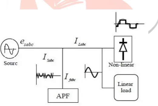
Fig. 1: Power system with non-linear load.
Fig. 1 shows a linear load and a non linear load connected to power system. The current of non linear load contains harmonics and so supply current IS also contains harmonics. This harmonic content in power line will cause problems such as power losses in distribution system, interference with communication systems, etc.
International standards concerning electrical power quality (IEEE-519, IEC 61000, EN 50160, among others) impose that electrical equipments and facilities should not produce harmonic contents greater than specified values, and also specify distortion limits to the supply voltage. Meanwhile, it is mandatory to solve the harmonic problems caused by those equipments already installed.
II.SHUNT ACTIVE FILTER
IJEDR1402050
International Journal of Engineering Development and Research (www.ijedr.org)1589
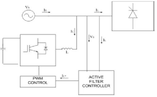
Fig. 2: Block diagram of Shunt Active FilterShunt Active Filter consists of two main blocks: (1) The PWM converter (power processing) (2) The active controller (signal processing).
The PWM converter is used for synthesizing the compensating current that should be drawn from the power system. Active filter controller is used to generate the compensating reference current, which are continuously passed to the PWM converter.
Figure 2 shows the block diagram of shunt active filter showing a voltage fed converter with a PWM current controller and shunt active filter controller which works in a closed loop manner. The converter should have high switching frequency so that harmonics current are accurately compensated. Generally, fPWM > 10fhmax where, fhmax is the frequency of highest order harmonic current. Figure also shows a DC capacitor along with IGBT which indicated active filter is built of voltage source converter.
III.CONTROL TECHNIQUES FOR SHUNT ACTIVE FILTER
Control strategy plays a major role in performance of shunt active filter, which consists of the following stages: 1. Source voltage and load current signals are sensed
2. Compensation currents are calculated using a control theory
3. The gating signals are generated for the active converter using PWM, Fuzzy logic or Hysteresis control techniques. In the second stage the compensating current can be generated by the following two domain methods:
a) Time Domain b) Frequency Domain
Frequency domain methods make use of Fast Fourier Transform (FFT). These methods are not preferred for calculating compensating currents due to their large computational time. Time Domain methods make use of instantaneous values to generate compensating current. There are two main time domain methods.1. The instantaneous active and reactive power or p-q theory 2. Synchronous reference frame or d-q theory In both these methods first voltages and currents are transformed from abc frame to stationary reference frame (p-q) or synchronously rotating frame (d-q).
A. The p-q Theory
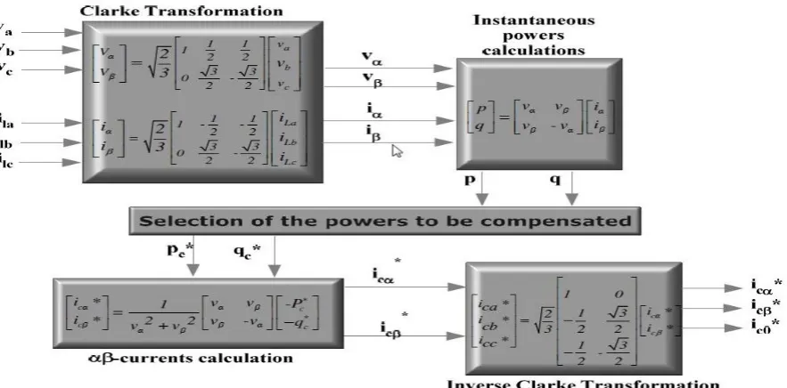
"The Generalized Theory of the Instantaneous Reactive Power in Three-Phase Circuits", also known as instantaneous power theory or p-q theory was proposed by Akagi in 1983. It is valid for steady state and transitory operation and it is based on the instantaneous values with or without neutral wire for three phase power system. Firstly the three phase voltages and current are transformed to α-β-0 coordinates with the help of Clark’s transformation then the instantaneous values of active and reactive power are calculated.
IJEDR1402050
International Journal of Engineering Development and Research (www.ijedr.org)1590
Fig. 3: Control method for shunt current compensation based on p-q theoryB. Hysteresis Current Control Technique
Hysteresis current control techniques offer very good dynamic response and simplicity in generating the gating signals for active converter.
Fig. 4: Hysteresis current control technique
In this method a feedback current control technique is used so that actual current continuously follows the command current limited by a hysteresis band. Above figure explains working of hysteresis controller for a half bridge inverter. The control circuit generates the sine reference current wave of desired magnitude and frequency, and it is compared with actual phase current wave. As the current exceeds a prescribe hysteresis band, the upper switch in half bridge is turned off and lower switch is turned on, as a result the output voltage transition from +0.5Vd to -0.5Vd and the current starts to decay. In same way as current crosses the lower band limit, the lower switch is turned off and the upper switch is turned on.
IJEDR1402050
International Journal of Engineering Development and Research (www.ijedr.org)1591
Figure 5 explains working of hysteresis technique. The source reference current is compared with source current and their difference is given to the hysteresis band which will generate the required gating signal for the active inverter. Here the switching frequency does not remain same but changes along with the current waveform.IV.SIMULATION RESULTS
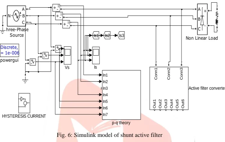
Shunt active filters are used to deal with the problems related to current harmonics due to the use of non linear loads in the system. Shunt active filter provide compensation for current harmonics and also help to maintain DC link voltage. Among many available methods to generate reference current for active filter, in this thesis instantaneous power theory (p-q theory) is used to generate reference current and then this signals are given to hysteresis current controller for generating switching signals. Figure 6 shows the Simulink model of shunt active filter using p-q theory and hysteresis current control technique.
Fig. 6: Simulink model of shunt active filter
Here a series RL load is used along with universal bridge as a non linear load. Simulations results are shown of, source voltage and load current before compensation of harmonics current and also results are shown of shun active filter currents, source current and dc link voltage after the compensation of non linear load currents.
Figure 7 shows MATLAB Simulink model for hysteresis current control in which the actual current continuously follows reference current within a proper hysteresis band upper and lower limits. Hysteresis current control decides the switching action of voltage source inverter.
Fig. 7: Simulink model for Hysteresis Current Control
Figure 8 shows MATLAB Simulink model for PI controller block which is used to maintain the DC link voltage which is proportional to difference between the actual and the reference voltages. The design of PI control parameters is difficult for a complex system hence they are obtained by trial and error method.
The actual value of DC link capacitor voltage is compared with a constant reference value of 700 V which is shown in fig. 8. Discrete,
Ts = 1e-006 s. powergui In1 In2 In3 In4 In5 In6 In7 p-q theory Vs v + -v + -v + -N A B C Three-Phase Source A B C +
-Non Linear Load
Is HYSTERESIS CURRENT Is3 Is2 Is1 i +-i +-i +-O u t1 O u t2 O u t3 O u t4 O u t5 O u t6 C o n n 1 C o n n 2 C o n n 3
Active filter converter
IJEDR1402050
International Journal of Engineering Development and Research (www.ijedr.org)1592
Fig. 8: Simulink model of PI controllerThe results of simulation of shunt active filter ware verified using MATLAB software. Table 1 shows the simulation parameters used for the simulink model.
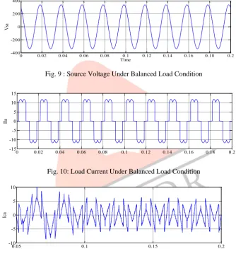
Fig. 9 : Source Voltage Under Balanced Load Condition
Fig. 10: Load Current Under Balanced Load Condition
Fig. 11: Compensation Current Under Balanced Load Condition
Fig. 12: Source Current Under After Compensation
Vo
PI
Discrete PI C ontroller2 700
0 0.02 0.04 0.06 0.08 0.1 0.12 0.14 0.16 0.18 0.2
-400 -200 0 200 400
Time
Vsa
0 0.02 0.04 0.06 0.08 0.1 0.12 0.14 0.16 0.18 0.2
-15 -10 -5 0 5 10 15
Il
a
0.05 0.1 0.15 0.2
-10 -5 0 5 10
Ica
0.05 0.1 0.15 0.2
-20 -10 0 10 20
Is
IJEDR1402050
International Journal of Engineering Development and Research (www.ijedr.org)1593
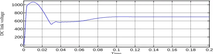
Fig. 13: DC Link Voltage Under Balanced Load ConditionTable 1
Simulation parameters
Source voltage (ph-ph, rms) 415 V
Source frequency 50 Hz
Load Resistance 50 Ω
Load Inductance 1 mH
DC side voltage 700 V
DC side capacitance 1000 μF
The results of source voltage, load current, compensation current and source current are shown in figure 9-13. The THD of source current has decreased from 30.55 % to 3.71 % after compensation. Simulation results show the effectiveness of shunt active power in reducing the current harmonics and improving the THD in source current.
Fig. 14: Harmonic spectrum of source current before compensation
Fig. 15: Harmonic spectrum of source current after compensation
0 0.02 0.04 0.06 0.08 0.1 0.12 0.14 0.16 0.18 0.2
0 200 400 600 800 1000
Time
DC
lin
k
vo
ltag
e
0 2 4 6 8 10 12 14 16 18 20
0 20 40 60 80 100
Harmonic order
Fundamental (50Hz) = 12.39 , THD= 30.55%
Mag
n
itu
de
0 2 4 6 8 10 12 14 16 18 20
0 20 40 60 80 100
Harmonic order
Fundamental (50Hz) = 12.38 , THD= 3.71%
Mag
ni
tu
IJEDR1402050
International Journal of Engineering Development and Research (www.ijedr.org)1594
The THD of source current are shown in Fig. 14 & Fig. 15. THD of source are 30.55% before compensation and 3.71% after compensation.V.CONCLUSION
A shunt active power filter has been investigated for power quality improvement. Various simulations are carried out to analyze the performance of the system. Simulation results show that the use of nonlinear load injects current harmonics in the system. The THD in case of nonlinear load are 30.55% which are reduced to 3.71% after compensation.
From literature survey it can be conclude that shunt active filter is a useful device for compensation of current harmonics due to nonlinear loads. The THD due to nonlinear loads can be brought to limits according to IEEE standards by using shunt active filter.
REFERENCES
[1] C. Shankaran, ―Power Quality‖, CRC press, 2002, pp: 1-23.
[2] R.C. Dugan, M. F. Mc Granaghan, ―Electrical power system quality‖, Mc Grow Hill publication.
[3] Hirofumi Akagi, ―New Trends in Active Filters for Power Conditioning‖, IEEE TRANSACTIONS ON INDUSTRY APPLICATIONS, VOL 32, NO 6, NOVEMBER DECEMBER 1996.
[4] Bhim Singh, Kamal Al-Haddad, Ambrish Chandra, ―A Review of Active Filters for Power Quality Improvement‖, IEEE TRANSACTIONS ON INDUSTRIAL ELECTRONICS, OCTOBER 1999.
[5] Hirofumi Akagi, ―Active Harmonic Filters‖, PROCEEDINGS OF THE IEEE, VOL. 93, NO. 12, DECEMBER 2005. [6] H Akagi, ―Instantaneous Power Theory & Applications To Power Conditioning‖, V John Wiley & Sons Publication.
[7] S.D. Round and D.M.E. Ingram, ―An Evaluation of Techniques for Determining Active Filter Compensating Currents in Unbalanced Systems‖.
[8] Suresh. Mikkili, A.K. Panda, ―PI Controller based Shunt Active Filter for Mitigation of Current Harmonics with p-q Control strategy using Simulation and RTDS Hardware’.
[9] Joao L. Afonso, H. J. Ribeiro da Silva and Julio. S.Martins ―Active Filters For Power Quality Improvement‖ 2001 IEEE Porto Power Tech.
[10] Francisco C., ―Harmonics & Power Systems‖, CRC Press.
[11] Fang Zheng Peng, ―Application issues of active power filter‖, international conference, Las Vegas, 1998, IEEE industry Applications Magazine, September/October 1998.
[12] Joao Afonso, Carlos Couto, Julio Martins, ―Active Filters with Control Based on the p-q Theory‖, IEEE Industrial Electronics Society Newsletter, vol. 47, nº 3, Sept. 2000.