DOI: 10.1051/epjconf/20158201047 C
Owned by the authors, published by EDP Sciences, 2015
Research of energy efficiency direct-heating systems with
sequential connection of space heaters with different
methods of heat consumption regulation
Maxim N. Morozovaand Pavel A. Strizhak
National Research Tomsk Polytechnic University, 634050 Tomsk, Russia
Abstract. A model of the building heating system, consisting of energy source, a distributed automatic control system, elements of individual heating unit and heating system is designed. Application Simulink of mathematical package Matlab is selected as a platform for the model. There are the specialized application Simscape libraries in aggregate with a wide range of Matlab mathematical tools allow to apply the “acausal” modeling concept. The conducted research of single-pipe heating system configuration and automatic control system allowed comparing the integral parameters of the systems with local and individual regulation. The results of research of thermal condition premises, situated in the extreme movement direction of the coolant are given. The conclusions about the possibility of increasing the operational efficiency of single-pipe heating system configuration in the implementation of distributed control systems are presented.
1. Introduction
In recent years issues of energy conservation, improving energy and resource efficiency are considered decisive in many countries [1,2].
Particular attention, as a rule, is given to activities aimed at improving the energy efficiency of administrative and industrial purposes buildings and facilities [3–9].
There are several active requirements for a modern heating system. On the one hand it is necessary to maintain the microclimate parameters at a comfortable level and on the other – it is required increasing energy efficiency of engineering building life support systems.
The aim of this work is to investigate a single-pipe building heating system in case of local regulation in heating unit and also in the case of individual regulators.
2. Simulation object
As a simulation object, a district heating system of a typical administrative building (for Russia) has been selected. The system consists of the individual heating unit (IHU), mainline inlet and outlet pipes,
aCorresponding author:[email protected]
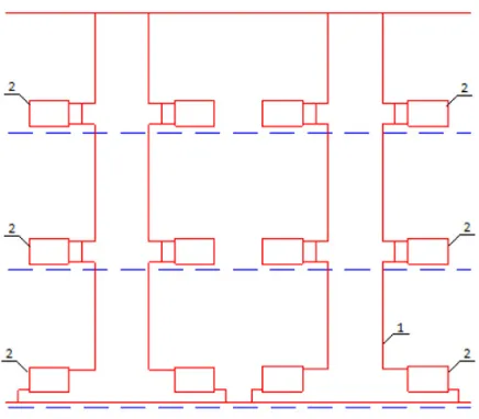
Figure 1. A schematic diagram of a single-pipe building heating system by a vertical configuration: 1 – water pipe, 2 – heating appliance.
risers, heating appliance and control valve. Heat supply of the building is provided by the central heating unit at the temperature chart 95/70◦C.
Entry heat supply system into the building carried out through heat metering point of IHU. The IHU has been designed under the “independent scheme” using pump circulation and mixing the coolant from the return pipeline to the feed [10,11]. The building heating system’s feature is the availability of both single- and double-pipe configurations.
As modeling object a vertical single-pipe configuration with overhead coolant distribution and heating appliances, connected in sequential groups, has been selected in this research work (Fig.1).
The system is a combined (heating appliances installed on the upper floors provided with a bypass, the lower floor – flow system).
3. Model of the building district heating system
The thermal model of the building has been developed to evaluate the energy efficiency of pipe heating systems with different methods of regulation.
The application Simulink of the mathematical package Matlab [12] has been selected as a platform for a model. An extension package Simscape, which implements a “physical” simulation concept [13], has also been applied to develop the model.
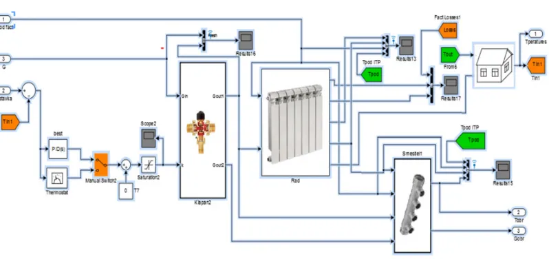
Model implementation in the Matlab package is based on representing of each individual functional component [12,13] in the form of s-functions and subsystems blocks (Figs.2,3).
The law of energy conservation for a typical premise is at the basis of the thermal model of the building heating system [14].
To simulate different mechanisms of heat transfer between model components laws Fourier, describing the mechanism of conductivity heat transfer and the Newton-Richman (convective heat transfer) has been applied [14].
Figure 2. The main thermal model blocks of the building district heating system.
Figure 3. A part of premise model.
In this context the model can be used as a tool at the technical-and-economic assessment development of energy management systems in accordance with ISO 50001:2011 “Energy management systems – Requirements with guidance for use” [15].
An example of applied problem is realization of an individual building thermal mode [16–19]. This assumes implementation of low heat demand mode, where the temperature of indoor air is reduced to an allowable parameters “heat-humidity” mode, regulatory documents, as well as economic reasons.
4. Modelling results
To achieve the set purpose of investigations, a series of numerical experiments has been carried out, aimed to analyze the influence of the external disturbing factor (outside temperature Tout) on premises thermal mode, containing the heating system:
1) with individual regulation;
Table 1. Results of system reaction at the external disturbing factor influence.
Outdoor temperature Regulation time treg, s ×104
Tout,◦C Premise 3rd floor (No 3) Premise 2nd floor (No 2) Premise 1st floor (No 1)
5. . .0 0,0608 0,0776 0,2655
0. . .−5 0,0628 0,1296 0,2661
−5. . .−10 0,0621 0,1284 0,2243
−10. . .−15 0,0623 0,0872 5,9
−15. . .−20 0,0598 0,0867 4,55
−20. . .−25 0,0585 0,088 4,58
−25. . .−30 0,0582 0,0925 4,6
−30. . .−35 0,067 0,1067 4,63
−35. . .−40 0,0532 0,1607 4,117
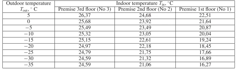
Table 2. Results of building thermal mode research in case of local regulation with weather compensator at the external disturbing factor influence.
Outdoor temperature Indoor temperatureTin,◦C
Tout,◦C Premise 3rd floor (No 3) Premise 2nd floor (No 2) Premise 1st floor (No 1)
5 26,37 24,68 22,51
0 25,68 23,92 21,64
−5 25,49 23,49 20,87
−10 25,32 23,05 20,04
−15 25,15 22,61 19,24
−20 24,97 22,18 18,45
−25 24,79 21,75 17,66
−30 24,59 21,32 16,89
−35 24,59 21,06 16,27
In each series of experiments three rooms located on different floors of the building (Fig.1) has been considered: vertical single-pipe configuration with sequential connections of heating appliances. As an external disturbing factor outside air temperatureTouthas been accepted. Temperature change has been
set in the range [−40;5]◦C with increments of 5◦C.
Comparative analysis of the first series modeling results showed that individual control of heating appliances provides stabilization of the controlled parameter – indoor air temperatureTin.
Estimation of the transient processes quality has been conducted by the regulation time treg. After modeling the specified temperature range of the external disturbing factor Tout obtained data have been processed. Results of this process are summarized in Table1.
Analysis of data (Table1) leads to the conclusion about the regulation time increasing for the 1st floor premise. The latter is explained by lack of coolant temperature at the inlet to the heating appliances. The individual (distributed) automatic control system cannot cope with its main objective – stabilizing indoor room temperature.
Comparative analysis of the second series modeling results showed that under the considered weather conditions the absence of individual regulation does not allow the heating system to maintain optimal thermal conditions of the premises (Table2).
Also, the analysis shows that the 3rd floor indoor air temperatureTinis inflated in the whole range
of external disturbing factor influence Tout during the entire heating season.
Uneven coolant distribution at heating appliances is the most important disadvantage of single-pipe heating systems. This problem cannot be solved even in case of installation modern controller with weather compensator (“weather-dependent” algorithm) in IHU.
Research has been shown that total modernization of heat supply system by installing individual regulators of heat consumption (distributed system) in addition to centralized controller allows getting qualitatively new opportunities. In this case, it becomes available to maintain the individual premises thermal modes, precise control in accordance with the PID, PD or PI-laws exclude overruns heat, which caused by inflated indoor air temperatureTin.
In this case there is an automatic coolant redistribution between heating appliances. Functioning of the considered system becomes the most optimal (in the hydraulic balance term) in the implementation of automatic balancing valves, which compensate the negative influence of individual regulators.
5. Conclusions
A model of the building district heating system, which allows investigating the problems of widespread single-pipe heating systems in closed to reality operating conditions has been developed.
The conducted researches provide an opportunity to evaluate the efficiency of various heating systems and its regulation variants: centralized in IHU using “weather-dependent” algorithm separately and also combined with individual regulation of heat consumption.
It is shown that even a single-pipe heating system configuration allows maintaining the building indoor climate parameters in the optimal range with less power consumption only in case of implementation of distributed control system (a combination of local regulation in IHU and individual – in each premise).
The reported study is supported by the Ministry of Education and Science of the Russian Federation Grant (project 2.1321.2014).
References
[1] V. Roshchanka, M. Evans, Playing hot and cold: how can Russian heat policy find its way toward
energy efficiency (Pacific Northwest National Laboratory, Washington, 2012)
[2] G. Keikkala, A. Kask, J. Dahl, V. Malyshev, V. Kotomkin, Energ. Policy B 35, 1452 (2007) [3] A. Korppo, N. Korobova, Energ. Policy B 42, 213 (2012)
[4] A. Boute, Pace Envtl. L. Rev. B 29, 746 (2012)
[5] Z. Wang, Y. Ding, G. Geng, N. Zhu, Energy Convers. Manage. B 77, 233 (2014) [6] G. Dall’O, L. Sarto, Energy and Build. B 67, 298 (2013)
[7] G. Mustafaraj, D. Marini, A. Costa, M. Keane, Appl. Energy B 130, 72 (2014)
[8] T. Berger, C. Amann, H. Formayer, A. Korjenic, B. Pospischal, C. Neururer, R. Smutny, Energy and Build. B 80, 517 (2014)
[9] M.D. Moldovan, I. Visa, M. Neagoe, B.G. Burduhos, Energy Procedia B 48, 924 (2014) [10] M. Zago, A. Casalegno, R. Marchesi, F. Rinaldi, Energies B 4, 2115 (2011)
[11] O. Ibrahim, F. Fardoun, R. Younes, H. Louahlia-Gualous, Build. Environ. B 72, 259 (2014) [12] M. Kiyan, E. Bingöl, M. Melikoglu, A. Albostan, Energy Convers. Manage. B 72, 147 (2013) [13] D. Broman, P. Fritzson, Proceedings of the 2nd International workshop on equation-based
object-oriented languages and tools, 59 (Paphos, Cyprus, 2008)
[14] P. Lauenburg, J. Wollerstrand, Proceedings of the 11th International Building Performance
[15] C. Eccleston, F. March, T. Cohen, Inside Energy: The Handbook for Implementing an ISO 50001
Energy Management Systems (CRC Press, 2011)
[16] M. Wallace, R. McBride, S. Aumi, P. Mhaskar, J. House, T. Salsbury, Chem. Eng. Sci. B 69, 45 (2012)
[17] S. Privara, Z. Vana, E. Zacekova, Energy and Build. B 55, 341 (2012)
[18] M. Maasoumy, M. Razmara, M. Shahbakhti, A. Sangiovanni Vincentelli, Energy and Build. B 77, 377 (2014)