ISSN (Print) : 2320 – 3765 ISSN (Online): 2278 – 8875
I
nternational
J
ournal of
A
dvanced
R
esearch in
E
lectrical,
E
lectronics and
I
nstrumentation
E
ngineering
(An ISO 3297: 2007 Certified Organization)
Vol. 5, Issue 2, February 2016
Comparisons of Different Controller for
Position Tracking of DC Servo Motor
Shital Javiya1, Ankit Kumar2
Assistant Professor, Dept. of IC, Atmiya Institute of Technology & Science, Rajkot, Gujarat, India1 PG Student, Dept of IC, Atmiya Institute of Technology & Science, Rajkot, Gujarat, India2
ABSTRACT:The accurate position control of DC servo motor is an important issue in industrial.This paper present position tracking of DC servo motor using different control strategy. Control strategy is requires to minimizing the steady state error. Here consider the no of controller like PID controller using different tuning method and MPC controller. This paper identifies and describes the design choices related to a PID controller and predictive controller for a DC servo motor. Performance of these controllers has been verified through simulation using MATLAB/SIMULINK software. According to the simulation results the Comparisons between PID (ZN), PID (GG) and MPC controller are given in this paper. The tuning method was more efficient in improving the step response characteristics such as, reducing the rise time, settling time and maximum overshoot in Position control of DC servo motor. Model predictive controller method gives the best performance and superiority of MPC method compare to other controller.
KEYWORDS:MPC, ZN, GG, PID, LQR
I.INTRODUCTION
Recently, DC servo motors have been widely used as robotics manipulation, actuator for automation control process, mechanical motion and direct drive application. Thus, we consider DC servo motor for position tracking because DC motor has some limitation to precision measurement of position rather than speed. For dc servomotor, rotor inertia are very small and time constant are extremely small. Therefore the result of motors has very high torque-to-inertia ratios for commercially available application. Thus, present work is based on DC servo motor SISO system for position control using control tool MATLAB. First, It is used to obtain the transfer function using mathematical model to design the PID controller. Then effectiveness of the design is checked by using MATLAB/Simulink. It was created simulation model at the MATLAB programmed and design a proportional integral derivative controller. Generally, DC servo motors has uncertain and nonlinear characteristics which degrade performance of PID controller. As we know motor is fast dynamic system and its sampling time is in milliseconds, this work intended to implement MPC on fast dynamic system. This work is to design a MPC controller for servo motor systems.
ISSN (Print) : 2320 – 3765 ISSN (Online): 2278 – 8875
I
nternational
J
ournal of
A
dvanced
R
esearch in
E
lectrical,
E
lectronics and
I
nstrumentation
E
ngineering
(An ISO 3297: 2007 Certified Organization)
Vol. 5, Issue 2, February 2016
II. BASICS OF DC SERVO MOTOR
The DC servo motor is basically a torque transducer that converts electric energy into mechanical energy. The small laboratory motors are servomotors, which is uses for positioning control in a variety of automation applications. DC servo motor is an electromechanical device in which the electrical input determines the position of motor armature. The armature is driven by an external DC voltage that produces the motor torque and the motor speed. The DC servo motor is used extensively in control systems, it is necessary to establish mathematical models of dc servo motors for analytical applications.
Fig 1: Basic servo system block diagram
The servomotors used in many industries today are used in a closed-loop servo system. A reference input is sent to the error detector which compare error signal with feedback signal and generate the error signal. Error signal given to the controller to minimize the error. Controller output fed to the DC servo motor to control the speed as well as Position of the servomotor. Directly mount the servomotor in a feedback device (like as an encoder or tachometer). This device changes mechanical motion into electrical signals and is used as a feedback loop. This feedback loop is then sent to the error detector, which compares the actual operation with that of the reference input. If there is an error, that error is fed directly to the controller, which makes the necessary corrections. In many servo systems, both velocity and position are monitored and measured.A normal servo is used to control an angular motion of between 0 and 180 degrees. The 360° rotation servos are continuous rotation servo. With the continuous rotation servo you can only control the direction and speed of the servo, but not the position of shaft. PWM is used for the control signal of servo motors. However, unlike DC motors it’s the duration of the positive pulse that determines the position, rather than speed, of the servo shaft.Servo motors work with full torque at high speeds. Servo motors have a position sensing device attached to the drive motor that reports the actual position of the motor shaft back to the motor controller.
III. SYSTEM MODEL AND SPECIFICATION
In this dc servo motor can be consider as a linear SISO system having 3rd order transfer function.The speed and position of a DC servo motor can be varied by controlling the field flux, the armature resistance or the terminal voltage applied to the armature circuit. The three most common speed control methods are field resistance control, armature voltage control, and armature resistance control. Here we consider the armature voltage control because servo motor is less sensitive to change in field current. In torque equation field flux is large enough. Thus, every small change in armature current Ia becomes much sensitive to the servo motor. As the armature of DC servo is less inductive and more resistive, time constant of armature winding is small enough. Thus dynamic response of armature controlled DC servo motor is much faster than that of field controlled DC servo motor.
ISSN (Print) : 2320 – 3765 ISSN (Online): 2278 – 8875
I
nternational
J
ournal of
A
dvanced
R
esearch in
E
lectrical,
E
lectronics and
I
nstrumentation
E
ngineering
(An ISO 3297: 2007 Certified Organization)
Vol. 5, Issue 2, February 2016
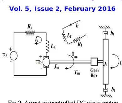
Fig 2: Armature controlled DC servo motor
The torque T is delivered by the motor is proportional to the product of the armature current Ia and the air gap flux Φ.
Ʈ= .
= .
Where, is constant. The torque can be written as,
Ʈ= . . .
Ʈ= .
Where, is also propositional constant. The back emf is proportional to the angular velocity,
= .
The speed of an armature controlled DC servo motor is controlled by the armature voltage Ea, which is supplied by a power supply .The differential equation for the armature circuit is by using Kirchhoff's voltage law,
+ + =
The armature current creates the torque which is applied to the inertia and friction is
+ =Ʈ
Taking the Laplace transforms of the above three differential equations,
( ) =
. . ( )
(
+
) ( ) +
. . ( ) =
( )
( + ) ( ) = . ( )
( ) =
(
+
)
( )
−
. . ( )
ISSN (Print) : 2320 – 3765 ISSN (Online): 2278 – 8875
I
nternational
J
ournal of
A
dvanced
R
esearch in
E
lectrical,
E
lectronics and
I
nstrumentation
E
ngineering
(An ISO 3297: 2007 Certified Organization)
Vol. 5, Issue 2, February 2016
( ) =
( )
−
. . ( )
(
+
)(
+
)
( )
( )
=
+ (
+
)
+ (
+
)
Fig 3. Model of DC servo motor
This transfer function is the Position control of DC servo motor. Estimation of model is done by system identification tool in MATLAB. According to this find the DC servo motor parameters to find the final system model transfer function.Finally, the transfer function of the DC servo motor is given as,
( )
( )
=
0.023
0.0046
+ 0.0269
+ 0.03053 +
0.001533
DC servo motor parameter
1) J-moment of inertia 0.02 kg.m2 2) Kt-torque constant 0.023 NM/A 3) Kb-electromotive force constant 0.023 Vs/rad
4) bm-linear viscous friction 0.03 Nms/rad 5) R-resistance 2 Ω 6) L-inductance 2.3 mH
IV. PID CONTROLLER FOR DC SERVO MOTOR
In the open loop control of actual DC servo motor that the motor positions start to drift over time indicating continuous addition of error within the same system. Second handed that should have no way to enforce the output of the motor to track the input voltage in the absence of any feedback loop. For open loop system feedback gain is not presented. Thus, it cannot give accurate output of shaft position for servo motor. To overcome this problem we used feedback loop in the system. In feedback path consider the feedback devices like Potentiometer, encoder, resolver etc. Its output compare with the desirable (Reference) input and generate the some error signal is degrade by using a controller. Controller output is control signal fed to the system model to control the position of servo motor. For controller purpose first use conventional PID of different tuning method.
ISSN (Print) : 2320 – 3765 ISSN (Online): 2278 – 8875
I
nternational
J
ournal of
A
dvanced
R
esearch in
E
lectrical,
E
lectronics and
I
nstrumentation
E
ngineering
(An ISO 3297: 2007 Certified Organization)
Vol. 5, Issue 2, February 2016
( ) =
∗
( ) +
( ) ( ) +
( )
( )
Where,
Kp : Proportional gain, a tuning parameter
Ki : Integral gain, a tuning parameter
Kd :Derivative gain, a tuning parameter e(t) : Error = Set Point – Present Value t : Time or instantaneous time
Methods of PID tuning:
No of PID tuning method are available for system control. Conventional PID tuning method, Ziegler-Nichols, Pole placement, Good-gain method and other soft computing method also present to gets accurate system output. Here two methods are applied first Ziegler-Nichols (Z-N) and second Good-Gain method for PID tuning.
[1] Z-N Method
Ziegler-Nichols method is a conventional PID tuning method. This method also known as online or continues cycling or ultimate gain tuning method. Ziegler-Nichols represented two methods way 1) Step response method 2) Frequency response method. Here applied based on the frequency response method for tuning the PID controller. In this method derivative time ( ) is set to zero and integral time ( ) set to infinity. This is used to get the initial PID setting of the systems. It has ultimate gain and frequency (Ku and Pu) from initial graph. Critical gain ( ) and periodic oscillations
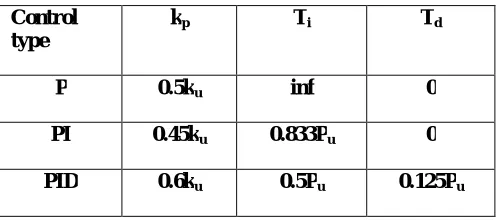
( ).Values of , are determined using the given formulas =0.6* , = / and = ∗ . Where, , , are calculated by using the formulas given in below table, Pu=2 / .
Table 1: Z-N tuning parameter
Control type
kp Ti Td
P 0.5ku inf 0
PI 0.45ku 0.833Pu 0
PID 0.6ku 0.5Pu 0.125Pu
[2] Good-Gain method
ISSN (Print) : 2320 – 3765 ISSN (Online): 2278 – 8875
I
nternational
J
ournal of
A
dvanced
R
esearch in
E
lectrical,
E
lectronics and
I
nstrumentation
E
ngineering
(An ISO 3297: 2007 Certified Organization)
Vol. 5, Issue 2, February 2016
V. SIMULINK MODEL OF PID CONTROLLER FOR DC SERVO MOTOR
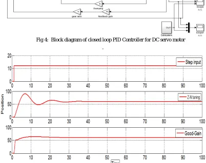
Fig 4: Block diagram of closed loop PID Controller for DC servo motor
Fig 5: Simulink Results of DC servo motor with PID controller
VI. MPC CONTROLLER FOR DC SERVO MOTOR
ISSN (Print) : 2320 – 3765 ISSN (Online): 2278 – 8875
I
nternational
J
ournal of
A
dvanced
R
esearch in
E
lectrical,
E
lectronics and
I
nstrumentation
E
ngineering
(An ISO 3297: 2007 Certified Organization)
Vol. 5, Issue 2, February 2016
construction of model from the input and the output data is known as model identification.Thus we need the ability to efficiently predict the future output behaviour of the system. By using a state-space model, the current information required for predicting ahead is represented by the state variable at the present time. A cost function is minimized subject to constraints to compute an optimal vector (u (k), u (k+1), u(k+2),.., u (k+1)) controls of future input signals at sample k over a specified time horizon, which is usually called control horizon . Finally the optimal value of control vector is then applied to the plant. Predictive horizon defines as at each sampling time instant k, the model of the plant (system) is used to predict the future behavior of the controlled plant over a specified time horizon. MPC controller has easy tuning method.MPC Minimize the operating cost and meeting constraints (optimization, economic).Superior for processes with large number of manipulated and controlled variables (Multivariable, MIMO).
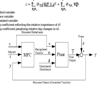
=
(
−
) +
∆
xi
= i -th controlled variabler
= i -th reference variableui
= i -th manipulated variableW
= weighting coefficient reflecting the relative importance ofxi
W
= weighting coefficient penalizing relative big changes inui
.Fig 6: Block Diagram of a SISO Model Predictive Control Toolbox
The information about the controlled process and prediction of the response of the process values according to the manipulated control variables are done by the process model. In order to design a good controller for a plant, model is usually required a controller designed on the basis of a model often works well than the one designed without a model. The object of this model is to predict the latest value taken by the noise (Disturbance).The process of construction of model from the input and the output data is known as model identification. There are mainly three components are available in MPC structure like as, the process model, the cost function and the optimizer. Then the error is reduced by the minimization of the cost function. Usually the cost function depends on the error between the future reference variable and the future controlled variable within limited time horizon. In the last step various types of optimization techniques are used and the output gives to the input sequence for the next prediction horizon.
ISSN (Print) : 2320 – 3765 ISSN (Online): 2278 – 8875
I
nternational
J
ournal of
A
dvanced
R
esearch in
E
lectrical,
E
lectronics and
I
nstrumentation
E
ngineering
(An ISO 3297: 2007 Certified Organization)
Vol. 5, Issue 2, February 2016
input and output disturbances. Increase the PH makes system critically damped with minimum settling time and no peak overshoot, further increase in PH makes system over damped increasing settling time.
Fig 7: Simulink model of MPC for DC servo system
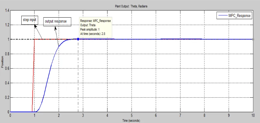
Fig 8: Simulation results of MPC controller for DC servo motor
ISSN (Print) : 2320 – 3765 ISSN (Online): 2278 – 8875
I
nternational
J
ournal of
A
dvanced
R
esearch in
E
lectrical,
E
lectronics and
I
nstrumentation
E
ngineering
(An ISO 3297: 2007 Certified Organization)
Vol. 5, Issue 2, February 2016
Table 2: Performance comparisons of different methods
Sr.No. Performance Index Z-N PID tuning Good-Gain PID Tuning
MPC
1 Rise time 5.2(sec) 4.03(sec) 1.57(sec) 2 Settling time 96.7(sec) 30.4(sec) 2.8(sec) 3 Peak Overshoot 24.7(%) 15.3(%) 0(%) 4 Steady state error 5(%) 2.5(%) 1.25(%)
Here, we can seen from table closed loop system response has very large rise time and settling time. And Peak Overshoot is also higher percentage. Using the PID controller we get better performance compare to without controller. However, for PID controller we need to tune the control parameter by using different tuning method. Thus, we would used two PID tuning method first, Ziegler- Nichols and second, Good-Gain. Ziegler- Nichols has more accurate transient response compare to closed loop system without controller such as, rise time, settling time and Peak overshoot is less. It has good performance but not sufficient for high performance system. So that, applied other method Good-Gain. It has very less rise time and settling time. And Peak overshoot is also very less compare to Z-N method. But it is not sufficient small parameter to achieve the good performance of servo system. Thus, MPC controller is used to get best performance of servo system.MPC has very small rise time 1.57 sec only compare to PID controller. Also, settling time is very less compared to other controller. MPC has zero percentage Peak overshoot.
VII.CONCLUSION
The basics concept of PID controller should be completed. The simulation of Closed-Loop DC servo motor using PID controller and MPC controller are done in MATLAB. Also applied two PID tuning method for Position control of DC servo motor. The use of the PID algorithm for control does not guarantee optimal control of the system or system stability. Thus, we use the higher performance controller Model Predictive Controller to achieve best system performance.MPC controller has very small rising time, less peak overshoot and less settling time.
REFERENCES
[1] Sidney R. Bowes, Fellow, Derrick Holliday “New Natural Observer Applied to Speed-Sensor less DC Servo and Induction Motors” IEEE Transaction Industrial Electronics, Vol. 51, No. 5, pp. 1025-1032, October – 2004.
[2] Gwo-Ruey Yu, Ming-Hung Tseng and Yuan-Kai Lin “Optimal Positioning Control of a DC Servo Motor Using Sliding Mode” IEEE Conference Control Applications, pp, 272-277 September – 2004
[3] Ali Mohamed Yousef “Experimental Set up Verification of Servo DC Motor Position Control Based on Integral Sliding Mode Approach” Wseas Transaction on Systems and Control, Vol. 7, pp. 87-96, July – 2012, Egypt
[4] Rong-Jong Wai , Rajkumar Muthusamy “ Fuzzy-Neural-Network Inherited Sliding-Mode Control for Robot Manipulator Including Actuator Dynamics”IEEE Transaction Neural Networks and Learning systems, Vol. 24, NO. 2, pp. 274-280, February -2013
[5] Vladim´ır Bob´al – Petr Chalupa – Marek Kubalˇc´ık “Self–Tuning Predactive Control Of Nonlinear Servo Motor” Journal of Electrical Engineering Vol. 61, pp. 365–372 , - 2010
[6] Nan yang,Dewei Li,Jun Zhang,Yugeng Xi “Model predictive controller design and implementation on FPGA with application to motor servo system”Science direct journal of control engineering Vol. 20, pp. 1229-1235, November - 2012.
[7] Piotr J. Serkies and Krzysztof Szabat “Application of the MPC to the Position Control of the Two-Mass Drive System” IEEE Transaction Industrial Electronics, VOL. 60, pp.3679-3688, September – 2013
[8] Guoyang Cheng and Jin-Gao Hu” An Observer-Based Mode Switching Control Scheme for Improved Position Regulation in Servo motors” IEEE-Transaction Control Systems Technology, Vol. 22, ,pp. 1883-1891, September – 2014
[9] Khalil. Mohamed, Ahmed.El Mahdy and Mohamed.Refai, “Model Predictive Control Using FPGA” International Journal of Control Theory and Computer Modeling (IJCTCM) Vol.5, April – 2015, Cairo, Egypt
BIOGRAPHY