ISSN (Print) : 2320 – 3765 ISSN (Online): 2278 – 8875
I
nternational
J
ournal of
A
dvanced
R
esearch in
E
lectrical,
E
lectronics and
I
nstrumentation
E
ngineering
(A High Impact Factor, Monthly, Peer Reviewed Journal)
Website: www.ijareeie.com
Vol. 7, Issue 3, March 2018
Speed Control of Smart Car using Fuzzy
Logic Controller
Arnob Senapati1, Akash Maitra2, Sumit Mondal3, Bodhisatwa Bhattacharya4, Binanda Kishore Mondal5, Abhishek Kumar Kashyap6
UG Student, Dept. of ICE, Calcutta Institute of Engineering and Management, West Bengal, India1,2,3
Assistant Professor, Dept. of EE, Adamas Institute of Technology, West Bengal, India4
Assistant Professor, Dept. of ICE, Calcutta Institute of Engineering and Management, West Bengal, India5, 6
ABSTRACT: The speed control system is one of the interesting terms in control system engineering. In this paper our target is to control and improve the performance of the speed of a smart car. To fulfill our desired aim we have used PID controller with different tuning rules like Ziegler-Nichols, Tyreus-Luyben and AMIGO. For speed control system PID controller does not give satisfactory output for our system because of the presence of nonlinearity. Therefore, in this system we have implemented Fuzzy Logic Controller to get the better response of this system. Fuzzy Logic Controller developed using real time data of the plant, that’s why it gives accurate response than conventional controllers. A comparative study between Fuzzy and conventional controllers has been done in this paper.
KEYWORDS: PID controller, Fuzzy logic controller, Z-N tuning, T-L tuning, Smart Car, Speed Control, Amigo tuning.
I. INTRODUCTION
Nowadays technology is growing rapidly, so with the demand of technology we have to develop a system which can be used in modern day applications. Cars are one of the most important inventions of science. It symbolizes the progress of science. But still a lot of inconvenience is faced by us due to traffic signals, slippery road, accidents etc. In this case Intelligent Transportation System (ITS) has come in recent years to solve these problems. But the research on the ITS field is not so easy due to many problems that’s why the Smart Car comes in the research field because in case of process control of smart cars, it can reflect the basic characters and the keys of the ITS field[4-5]. That’s why researching about the smart car system may provide a good outcome that can be implemented in further studies. A Smart Car includes modern technology like GPS detection, car positioning system, speed control, obstruction detection, distance measurement and many more but the speed control is the most important and challenging aspect of a Smart Car. In this project PID controller is used to control the Speed but due to the system with time delay it will not give the satisfactory result. To improve the performance and control of the speed, concept of Fuzzy Logic Controller is introduced in Smart Car [1-2].
In many research papers PID controller with ZN, TL rule and IMC controller is also used for control speed of smart car. The controllers could not give the satisfactory result. So, in this paper AMIGO tuning rule is introduced and give much better result. Many researches implement the software techniques in hardware like wireless remote control method.
II. MATHEMATICAL MODEL OF SMART CAR
Intelligent vehicle technologies are very important nowadays for enhancement of road safety, road transportation, operational efficiency and increasing driving pleasure. Intelligent or autonomous vehicle technology is subjected to drive the vehicle autonomously along the road with no or limited assistance from humans. Advanced sensors and Microprocessors are added in intelligent vehicles to provide extra features like safety, navigation, car parking etc.
ISSN (Print) : 2320 – 3765 ISSN (Online): 2278 – 8875
I
nternational
J
ournal of
A
dvanced
R
esearch in
E
lectrical,
E
lectronics and
I
nstrumentation
E
ngineering
(A High Impact Factor, Monthly, Peer Reviewed Journal)
Website: www.ijareeie.com
Vol. 7, Issue 3, March 2018
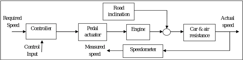
Fig 1: Model of a smart car
The block diagram of a smart car is given below. Which shows how the speed, road inclination are measured with the added car and air resistance by the controller. The controller takes necessary control action to give desired output.
Required Actual Speed speed
Control Measured Input speed
Fig 2: Block diagram of Car Let us define,
U = Input (Unit Step) V = Velocity (m/sec)
M = Mass of the car (Kg) = 200 B = Friction (Newton) =1
= Continuous time delay = 0.5
The mathematical equation of the smart car system is given below:
M ( )= U (t) – B*V (t) --- (i)
By applying Laplace Transform on equation (i) we get, s*M*v(s) = u(s) – B*v(s) --- (ii)
Therefore from equation (ii) we get the transfer function of the system as,
( )
( )= --- (iii)
It is challenging to build an accurate model of the car’s physical properties with the reason of power voltage, the wind resistance and the road friction keep changing. That’s why a time lag can be used with the system to obtain most accurate performance, which is defined as follows,
( )
( ) = --- (iv)
Now by putting the values of M, B and τ we get the smart car mathematical model as follows, Controller Pedal
actuator
Engine Car & air resistance Road
inclination
ISSN (Print) : 2320 – 3765 ISSN (Online): 2278 – 8875
I
nternational
J
ournal of
A
dvanced
R
esearch in
E
lectrical,
E
lectronics and
I
nstrumentation
E
ngineering
(A High Impact Factor, Monthly, Peer Reviewed Journal)
Website: www.ijareeie.com
Vol. 7, Issue 3, March 2018
( )
( ) =
. --- (v)
III. SPEED CONTROL OF SMART CAR USING PID CONTROLLER
PID control algorithm is the most classical technique to control speed and position of various systems. They are widely used in industry and have been universally accepted for controlling the machineries and equipments. The popularity of PID controllers can be attributed partly to their robust performance in a wide range of operations, functional simplicity and straightforward manner. PID control is implemented as either stand-alone control, or on DCS, SCADA and PLC control systems.
Fig 3: Simulink Model of PID controller
A. Tuning of PID
controller:-PID controllers are probably the most widely used industrial controller. controller:-PID tuning method is a popular method of tuning PID controller. In closed loop tuning method, a critical gain is introduced in the forward path of the control system. The high value of the gain takes the system to the verge of instability. It creates oscillation and from the oscillations, the value of frequency and time are calculated. After calculating the value of and we are able to determine the parameters of PID controller. There are many types of tuning rule available such as Ziegler-Nichols, Cohen and Coon, Astrom and Hagglund, Tyreus-Luyben etc. Here we apply Z-N, T-L and Amigo tuning rule and
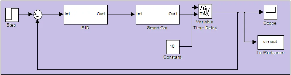
Fig 4: Simulink Model of Smart Car System with PID controller
Ziegler-Nichols tuning rule:-
ISSN (Print) : 2320 – 3765 ISSN (Online): 2278 – 8875
I
nternational
J
ournal of
A
dvanced
R
esearch in
E
lectrical,
E
lectronics and
I
nstrumentation
E
ngineering
(A High Impact Factor, Monthly, Peer Reviewed Journal)
Website: www.ijareeie.com
Vol. 7, Issue 3, March 2018
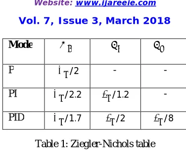
Table 1: Ziegler-Nichols table
From the sustained oscillation of system’s simulink model we get the value of ultimate gain = 30.4 and ultimate period = 42. Which implies that proportional gain ( ) = 18.24, integral gain ( = ) as 0.8685and derivative gain ( = ∗ ) as 91.9296.
Fig 5: Response of Smart car system using Z-N method
2. Tyreus-Luyben tuning rule:
Tyreus-Luyben tuning method is the improvement of the Ziegler-Nichols method. The objective of this method is to make the system response less oscillatory.
The tuning formula for T-L rule for getting the PID parameters and the response by using T-L tuning rule is given below:
Table 2: Tyreus-Luyben table
Mode P /2 - -
PI /2.2 /1.2 -
PID /1.7 /2 /8
Mode PI /3.2 2.2 -
ISSN (Print) : 2320 – 3765 ISSN (Online): 2278 – 8875
I
nternational
J
ournal of
A
dvanced
R
esearch in
E
lectrical,
E
lectronics and
I
nstrumentation
E
ngineering
(A High Impact Factor, Monthly, Peer Reviewed Journal)
Website: www.ijareeie.com
Vol. 7, Issue 3, March 2018
As we get the and value from the sustained oscillation and by putting those values on the table. Which implies proportional gain ( ) = 13.81, integral gain ( = ) =0.1494 and derivative gain ( = ∗ ) = 92.0666.
Fig 6: Response of Smart car system using T-L method
3. Amigo (Approximate M- constraint Integral Gain Optimization) tuning rule:
From the Z-N tuning rule we cannot get the satisfactory response. So many modifications were done on the Z-N method to get the satisfactory result. Amigo tuning rule is a rule where the entire procedure is same as Z-N but this rule consists of applying a set of equations to calculate the parameters of the controller. The behavior of the systems which can be approximated by First Order Plus Dead Time model or Integrating Plus Dead Time model, on those systems Amigo tuning rule can be applied.
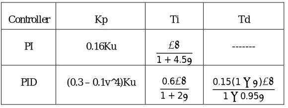
The Amigo tuning table and the response of the system by Amigo tuning method is given below:
Table 3: Amigo tuning table
Now in the case of Amigo controller also we calculate the K , and values from the Ku and values measured from the sustained oscillation graph. Then we get the control parameters proportional gain ( ) = 9.119, integral gain ( = ) =0.4139 and derivative gain ( = ∗ ) = 57.35.The response of the smart car system with the Amigo control action is given below:
Controller Kp Ti Td
PI 0.16Ku
1 + 4.5
---
PID (0.3 – 0.1v^4)Ku 0.6
1 + 2
ISSN (Print) : 2320 – 3765 ISSN (Online): 2278 – 8875
I
nternational
J
ournal of
A
dvanced
R
esearch in
E
lectrical,
E
lectronics and
I
nstrumentation
E
ngineering
(A High Impact Factor, Monthly, Peer Reviewed Journal)
Website: www.ijareeie.com
Vol. 7, Issue 3, March 2018
Fig 7: Response of Smart car system using Amigo tuning rule
IV. SPEED CONTROL OF SMART CAR USING FUZZY LOGIC CONTROLLER
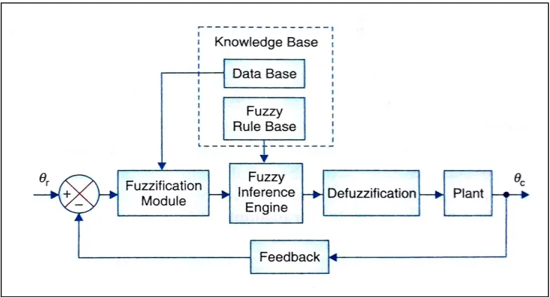
The Fuzzy Logic Controller is intended to have two fuzzy state variables and one control variable for accomplishing speed control of the Smart Car. Fuzzy Controllers are very simple conceptually. They consist of an input stage, a processing stage, and an output stage. The input stage maps sensor or other inputs, such as switches, thumbwheels, and so on, to the appropriate membership functions and truth values. The processing stage invokes each appropriate rule and generates a result for each, then combines the results of the rules. Finally, the output stage converts the combined result back into a specific control output value. The most common shape of membership functions is triangular, although trapezoidal and bell curves are also used, but the shape is generally less important than the number of curves and their placement. In Figure 8 shows a block diagram of Fuzzy logic based control system.
ISSN (Print) : 2320 – 3765 ISSN (Online): 2278 – 8875
I
nternational
J
ournal of
A
dvanced
R
esearch in
E
lectrical,
E
lectronics and
I
nstrumentation
E
ngineering
(A High Impact Factor, Monthly, Peer Reviewed Journal)
Website: www.ijareeie.com
Vol. 7, Issue 3, March 2018
For the fuzzy logic controller the input variables are error (E) and rate change of error (∆ ), and the output variable is controller output (Speed). Triangular membership functions are used for input variables and the output variable. Each variable has 5 membership functions. Thus, there were total 25 rules generated. The universe of discourse of error, rate of error and output are [0, 100], [0, 100] and [0, 150] respectively.
The rule base framed for Smart Car is tabulated in Table 5. Linguistic variables for error, rate of error and controller output are tabulated in Table 4.
Table 4: Linguistic variables
Table 5: Rule Base Framed for Smart Car
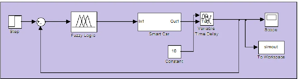
Figure (9) shows the Fuzzy logic controller designed in MATLAB Simulink by using the rule base designed above in table5. It shows the simulink model for Smart Car.
Fig 9: Simulink Model of the Smart Car with Fuzzy Logic Controller
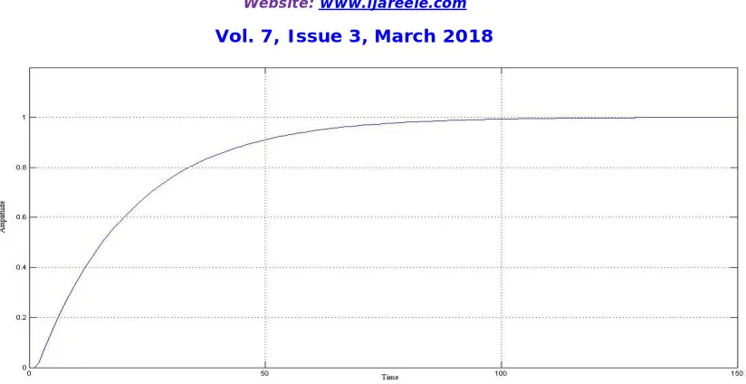
The corresponding Amplitude vs. Time Plot for Fuzzy Logic Controller shown in Figure (10). NL NS ZE PS PL
Negative Large
Negative Small
Zero Error
Positive Small
Positive Large
E/∆E NL NS ZE PS PL PL ZE PS PL PL PL
PS NS ZE PS PL PL
ZE NL NS ZE PS PL
NS NL NL NS ZE PS
ISSN (Print) : 2320 – 3765 ISSN (Online): 2278 – 8875
I
nternational
J
ournal of
A
dvanced
R
esearch in
E
lectrical,
E
lectronics and
I
nstrumentation
E
ngineering
(A High Impact Factor, Monthly, Peer Reviewed Journal)
Website: www.ijareeie.com
Vol. 7, Issue 3, March 2018
Fig 10: Response of the Smart Car system using Fuzzy Logic Controller
V. RESULT
Here the performance of PID controller with different tuning rules and Fuzzy controller are analyzed. The result has shown the performance of different controllers with better responses and tuning the controller gains for different cases such as eliminating overshoot, rise time and steady state error. The data analysis for different controller are tabulated below (Table6)
Table 6: The Data Analysis of Speed Control of a Smart Car
VI. CONCLUSION
In this paper we propose a scheme regarding speed control of a smart car which is based on Fuzzy controller and also we have analyzed the performance of it. Here, we have also use PID controller with different tuning rule and they give satisfactory result but not up to the mark. That’s why; we have used Fuzzy Logic Controller and get better response which is superior to PID. Meanwhile, the Fuzzy Logic Controller has a good ability to accommodate. Speed control based on Fuzzy Logic Controller attains good stability, zero overshoot and reduces the difficulty for parameter adjustment. In application the Fuzzy Logic Controller is less demanding and has strong operability. Here, we get good response but not the best response, so to achieve the best response, in future; we may use Internal Model Controller, Adaptive Controller and Neuro-Fuzzy Controller. In order to achieve best speed control we need more precise and a depth study of these subject.
Transfer Function Non linear Controller Rise Time (Tr)
(sec)
Settling Time (Ts)
(sec)
Maximum Overshoot (M %) Smart Car PID controller with Z-N
tuning rule
20 108 63.8
Smart Car PID controller with T-L tuning rule
42 213 10
Smart Car PID controller with Amigo tuning rule
31 231 52.4
ISSN (Print) : 2320 – 3765 ISSN (Online): 2278 – 8875
I
nternational
J
ournal of
A
dvanced
R
esearch in
E
lectrical,
E
lectronics and
I
nstrumentation
E
ngineering
(A High Impact Factor, Monthly, Peer Reviewed Journal)
Website: www.ijareeie.com
Vol. 7, Issue 3, March 2018
ACKNOWLEDGEMENT
I hereby express my sincere gratitude to the Assistant prof. B.K.Mandal, Dept. of Instrumentation and Control Engineering for providing us with the necessary arrangement for the completion of our project. Also express my sincere gratitude to the Assistant prof. A.K.Kashyap to guide me in every step for the completion of the project. Without their valuable guidance and support the project would not have been a success. I thank them for the good will and encouragement extended to us.
REFERENCES
[1] Nagrath, I.J. and M. Gopal, Control Systems Engineering, 3rd edition, New Age Publishers, 2000.
[2] Driankov, D., H. Hellendoorn and M. Reinfrank,An Introduction to Fuzzy Control,2nd edition, Springer International Student Edition, 2001. [3] František Duchoň, Peter Hubinský, Jaroslav Hanzel, Andrej Babinec,Michal Tölgyessy, Intelligent Vehicles as the Robotic Applications, Procedia Engineering, Volume 48, 2012, Pages 105-114.
[4] Procedia Engineering, Volume 48, 2012, Pages 105-114, Visionbasedintelligent vehicles: State of the art and perspectives, Roboticsand Autonomous Systems, Volume 32, Issue 1, 31 July 2000, Pages1-16.
[5] A.I. Chelovechkov, B.M. Chistoserdov, S.V. Baidikov, A two-loop frequency-domain electromagnetic induction system for detection ofanomalous objects, Russian Geology and Geophysics, Volume 49,Issue 8, August 2008, Pages 628-632.
[6] Aurelio Piazzi, Antonio Visioli, A noncausal approach for PID control, Journal of Process Control, Volume 16, Issue 8, September2006, Pages 831-843.
[7] Wayne M. Saslow, Chapter 12 - Faraday's Law of Electromagnetic Induction, Electricity, Magnetism, and Light, 2002, Pages 505-558.
[8] Benoit Dupont de Dinechin, Christophe Monat, Patrick Blouet, Christian Bertin, DSP-MCU processor optimization for portable applications, Microelectronic Engineering, Volume 54, Issues 1–2, December 2000, Pages 123-132467.
[9] Yang, X.-l.: Application of PID Arithmetic in Aptitude Vehicle. Experiment Science and Technology (August 2010)