Improved SRF Controller Based on DVR for Grid Connected Wind Energy
System
1
MALOTH CHANDRA SEKHAR NAIK, 2B.ANUSHA, 3DASANAM SHIREESHA
1
M.E. in EE Department, Indian institute of Science, Bangalore (iisc Bangalore)
2
M.Tech Scholar, Dept of EEE, CMRCET, Hyderabad
3
Assitant Professor, Dept of EEE, CMRCET, Hyderabad
1[email protected], 2[email protected], 3[email protected]
Abstract- The production of wind generation has expanded considerably today. The main problem with wind generation system is to regulate the voltage at wind turbine terminals even under abnormal grid conditions. This is mainly as a result of consumption of non active power from the grid during grid disturbances. This paper presents an improved Synchronous Reference Frame control namely Dual Decouple Synchronous Reference Frame (DDSRF) control for Dynamic Voltage Restorer (DVR) to upgrade the dynamic response of wind energy system. The main objective of the proposed control strategy is to stabilize the voltage at the wind turbine terminals under symmetrical sag/swell and asymmetrical fault conditions. Simulation studies have been performed in MATLAB/SIMULINK to manifest the effectiveness of proposed control strategy. The superiority of the proposed control strategy over conventional SRF method is demonstrated under unbalanced conditions through MATLAB simulation results
Keywords Dynamic voltage restorer (DVR); Low Voltage Ride Through Capability (LVRT); Point of Interconnection (POI); Dual Decouple Synchronous reference frame control technique (DDSRFT).
1. INTRODUCTION
The escalating infiltration of wind energy has enforced the transmission network operators to define latest grid codes to maintain the grid discipline, which is a challenging task for power engineers. Earlier, the wind turbines were tolerable to cut off during abnormal condition due to its small share of total generation systems. Of late, increased diffusion levels of wind farms badly affect the grid stability. To circumvent these problems, the grid operators in most of the countries have recognized the rigorous grid codes to meet LVRT capability.. Hence, wind generator disconnection is not possible during any outage in grid to defend the grid from voltage instability problems [1], [2]. Most of the existing wind turbines today are operating either with DFIG or PMSG using power electronic devices [3-5]. However, considerable share of fixed speed induction generators with no power electronics are still in operation all over the world. The important problem with fixed speed induction generator is the incompetence to withstand during voltage disturbance in the grid. Any voltage disturbance such as sag or swell occurring in in grid leads to torque unbalance between wind turbine and induction generator, which in turn increases the shaft speed and stress on mechanical drive system. In this situation wind generators are normally detached from the grid for safeness. But latest grid codes demand that the wind turbines must remain connected despite the disturbances in the grid to comply the latest grid
and precise information about the grid parameters is required for DVR control algorithm. Hence, this paper explores, an improved SRF control method, which is based on Dual Decouple synchronous Reference Frame (DDSRF) PLL for DVR control is
presented. The remainder of the paper is organized as follows. Section 2 elucidates grid code requirement for wind farm. Section 3 presents about the DVR and proposed control scheme. Section 4 summarizes the simulation results. Section 5 draws the conclusions.
2. CONNECTION OF WIND FARMS TO GRID: GRID CODE REQUIREMENTS
Fig. 1. Grid code requirements for LVRT With the fast raise in installation of wind generators,
it becomes obligatory to necessitate wind farms to perform as much as possible as conventional generators to maintain voltage and frequency both in steady state as well as in transient condition. Conventionally wind turbines are cut off from the grid during abnormal conditions in the grid. Under abnormal grid conditions, the voltage dip at the wind farm terminals cause the stator current to rise and leads to annihilation of the machine. In the past, the concentration of wind turbine was little and detachment of wind farm from the power network was not a major problem. In present state, the dispersion of wind farms is high and detachment of wind farms creates serious voltage instability problem. To avoid this condition, the grid operators have defined grid codes to meet the ride through capability under adverse voltage disturbances in the grid. The main aim of the grid codes for wind farms is to ensure reliable and secure of the power system.
One of the most important grid code requirements set by transmission system operators for wind farms are Low voltage ride through capability and fault ride through capability. According to latest grid codes, wind farms must be in service for a specific period of time without tripping from the grid under fault conditions. The grid code regulations may differ from nation to nation and from structure to structure. Variable speed wind turbine converters can act as reactive power compensation devices and support the voltage at the wind farm terminals during low voltage conditions. But fixed speed induction generators do not contribute to voltage support as variable speed wind turbines owing to huge reactive power absorbed by induction generators in the course of fault conditions. Hence to enhance the LVRT capability of fixed speed induction generators, DVR is forged at the point of interconnection to control the voltage at the generator terminals.
3. PROPOSED SYSTEM AND PROPOSED DVR CONTROL SCHEME
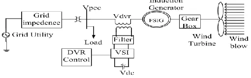
3.1 Proposed system under considerationThe proposed system under consideration is presented in Fig. 2. The DVR is placed between the distribution grid and wind source through injection transformer and filter. DVR adds required compensating voltage through series injection transformer to keep the balanced sinusoidal wind generator voltage during the voltage disturbances in the grid.
Voltage across the wind turbine from the Fig. 2. Vw=Vpcc+VDVR (1)
Where
Vw is the wind generator terminal voltage Vpcc is voltage at the point of interconnection VDVR is the voltage across transformer HV winding
The voltage VDVR is given by (Nh/Nl)*V0
Where
Nh is the number high voltage winding turns Nl is the number low voltage winding turns
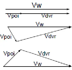
DVR produces controllable voltage V0 (VDVR) with suitable magnitude and phase shift. Under typical conditions, DC/AC converter output voltage VDVR is zero. When the point of interconnection voltage is changed due to voltage disturbances and faults in the grid side, DVR produces controllable magnitude and angle to preserve the voltage at the generator terminals constant as shown in the phasor diagrams in Fig. 3.
Fig. 3. Phasor Diagrams.
3.2 Proposed Control Scheme for DVR
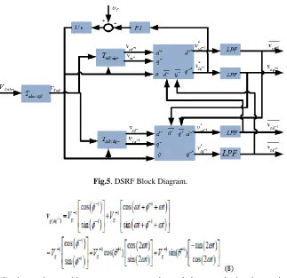
In this section, an improved Dual Decouple Synchronous Reference Frame control technique (DDSRFT) for DVR is presented. Fig. 4 shows the suggested DVR control scheme with DDSRF PLL.
As shown in Fig.4, Dual Double Synchronous Reference Frame (DDSRF) Phased locked loop is utilized for DVR to extract the phase angle and amplitude of the grid voltage to synchronize with wind terminal voltage under polluted grid conditions. Fig. 4 shows the the suggested DVR control scheme with DDSRF PLL. The extraction of phase angle is DDSRF PLL shown in Fig. 5, consists of a decouple
network which incorporates two synchronous reference frames with positive and negative sequence voltage vectors. The dual SRF composes of two rotating reference frames: dq+1, spinning with the positive synchronous speed (W+) and whose angular positive is ϴ’, and dq-1, turning with the opposite synchronous speed (W -) and whose angular positive is -ϴ’. The decoupled network allows appropriate segregation of the negative and positive sequence voltage components from an unbalanced grid voltage vector.
In general three phase grid voltages are expressed as in Eq. (2).
Fig. 4. DVR control scheme.
Fig.5. DSRF Block Diagram.
Eq. (7) and Eq. (8) shows that positive sequence rotating reference frame consists of the negative sequence AC voltage component which rotates at double the grid frequency and the negative sequence rotating reference frame consists of positive sequence voltage component which oscillates at double the grid frequency. These Eq. (7) and Eq. (8) can be considered as inputs to the decoupling network. The
decoupled network is shown in Fig. 6, which completely attenuates, the AC ripples on the dq+1 and dq−1 reference frame signals.
Low pass filter is used to extract the DC Signals from the positive sequence and negative sequence voltage components. The DC signals are cross coupled with decoupled network to eliminate the interactions between sequence components.
The q-axis component of positive sequence SRF is utilized to extract the phase angle with PI and integrator block. The extracted phase angle from DDSRF PLL is utilized to obtain direct axis and quadrature axis components of grid voltage from the unbalanced grid voltage using Park’s transformation. The unbalanced grid voltage contains ac as well as dc component, which is given in Eq. 10 and Eq.11.
As displayed in Fig. 4, the DC voltage controller maintains the DC bus voltage constant by comparing reference DC voltage of VSI and actual DC voltage of VSI.The DC voltage controller output is treated to be loss component of voltage. This loss component of voltage is summed to the d axis component of source voltage to generate the reference d axis component of wind terminal voltage.
The magnitude of fluctuating wind generator voltage Vw is regulated to the reference voltage Vw* by another PI controller. The PI controller output is taken as reactive component of vq. The reference q axis component of fluctuating wind terminal voltage is generated by adding reactive component of wind terminal voltage and dc component of Vsq.
reference wind terminal voltage Vwd* and Vwq* are converted to abc frame by inverse park transformation (Vwa*, Vwb* and Vwc*) .The error between these reference wind terminal voltages and actual measured fluctuating voltage are passed to PWM controller to develope the desired gating signals for voltage source converter. DVR injects necessary compensating voltages (Vca.Vcb, and Vcc) in series with the AC network to maintain wind terminal-voltage balanced and sinusoidal.
4. DISCUSSION OF SIMULATION
RESULTS
4.1. Simulation results
. The test system consists of wind energy system, distribution grid, DVR, coupling transformer and filter. In this section, substantial simulation studies have been accomplished in Matlab Simulink environment to observe the performance of DVR for
Fig. 7. Three phase grid voltage.
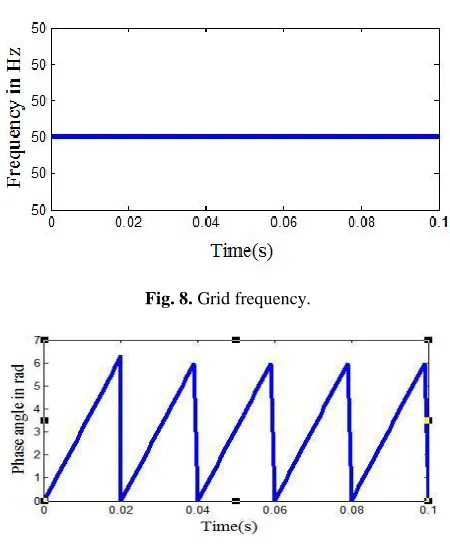
Fig. 8. Grid frequency.
Fig. 9. Phase angle of grid voltage
Fig. 10. Sine and Cosine signals.
4.1.1. Case 1: Dynamic performance of DVR under voltage sag condition
The performance of DVR for grid connected FSIG is demonstrated under dynamic sag condition as shown below. At the begining, the system operates under steady state condition and the balanced sag of 50% is introduced at 0.2 sec and lasts for 100ms as portrayed in Fig. 11. The proposed DVR responds to voltage
Fig. 11.Voltage Sag.
Fig. 12. DVR injected voltage under voltage sag.
Fig. 13. Voltage across wind generator under voltage sag.
In this way DVR protects the wind turbine by reducing the huge stress on the mechanical drive train system. The overshoots in induction generator current and DC link voltage is notably reduced with DVR compensated voltage as depicted in Fig. 16 and Fig. 17. The results portrayed in this case justify DVR control algorithm of to regulate the wind turbine voltage balanced and sinusoidal.
Fig. 15. Induction Generator Electromagnetic torque oscillations under voltage sag.
Fig.16. Induction generator current under voltage sag
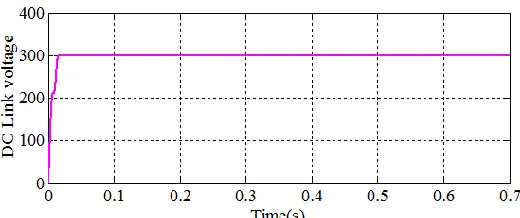
Fig. 17. DC link voltage under voltage sag.
4.1.2: Case 2: Dynamic performance of DVR under voltage swell condition
The effectiveness of DVR on the performance of fixed speed induction generator is demonstrated during voltage swell. In this case, the voltage swell in the grid is initiated as shown in Fig.18 at t=0.2 sec and is cleared after few cycles at 0.3 sec. The proposed DVR responds to voltage swell and injects
Fig. 18. Voltage swell.
Fig. 19. DVR injected voltage under voltage swell.
Fig. 20. Voltage across wind generator under voltage swell.
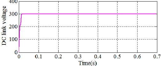
Fig. 21. DC link voltage under voltage swell.
Fig. 23. Electromagnetic torque oscillations under voltage swell.
4.1.3: Case 3: Dynamic performance of DVR under LG fault condition
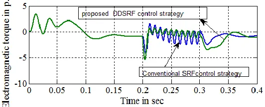
To improve the dynamic performance of DVR, the proposed DVR control strategy has been tested and compared with the conventinal SRF based DVR control under unbalanced condition. An LG fault at grid side is realized at t=0.2sec and persisted up to 0.3sec as shown Fig. 24. The voltage unbalance is clearly noticed with negative sequence component. The DVR injects the compensating voltage which compensates the negative sequence component to
regulate the voltage at the wind turbine terminals. The injected voltage of DVR and voltage at the wind farm terminals is shown in Fig. 25 and Fig. 26. The negative sequence unbalanced voltage component creates the double frequency oscillations in induction generator electromagnetic torque, shaft speed, rotor current.The pulsations in the electromagnetic torque, shaft speed and rotor current are very high with the traditional SRF based DVR control as shown in Figs. 27-30.
Fig. 24. LG fault in the grid side.
Fig. 26. Voltage across wind generator under LG fault.
Fig. 27. Electromagnetic torque under LG fault.
Fig. 28.Induction generator speed under LG fault.
Fig. 29.Induction generator current with SRF control.
Fig. 30. Induction generator current with the proposed DDSRF control.
This causes high stress on the mechanical drive system which inturn leads to disconnection of wind turbine. However, with the proposed control for DVR, the ripples in the electromagnetic torque ,rotor
complex multiple transormations to extract the grid phase angle
5. CONCLUSION
An improved synchronous reference frame control method has been presented in this paper for voltage compensation. The suggested control scheme is tested for symmetric and asymmetric fault conditions. The proposed DVR control algorithm has been confirmed through Matlab/Simulation results. The simulation results show that the ripples and overshoots that appear in DC Link voltage, rotor hub speed and electromagnetic torque are greatly reduced with the help of DVR under adverse grid conditions.. It has also been shown from the results that the application of DVR can productively alleviates voltage dips at the generator terminals and assist the wind turbine to stay connected even under abnormal conditions.The effectiveness of the proposed strategy has been investigated by comparing with the traditional control method under asymmetric fault conditions in MATLAB
References
[1] D. Ramirez, S Martinez, C.A Platero, F. Blazquez, R.M.de Castro, “Low-Voltage Ride-Through Capability for wind Generators based on Dynamic Voltage Restorers”, IEEE Trans. Energy Convers,vol. 26,no.1, pp.195-203,2011.
[2] L. B SHI, C.WANG, L.YAO, Z.WANG, “Analysis of Impact of Grid-Connected Wind Power on Small Signal Stability, Wind Energy”,vol. 14,pp. 517–537,2011.
[3] P. Flannery, G.Venkataramanan, “Unbalanced Voltage Sag Ride-Through of a Doubly Fed Induction Generator Wind Turbine with Series Grid Side Converter”, in:proc. Of IEEE Industry
Applications Society Annual Meeting, IAS, pp.1-8,2008.
[4] D.Santos-Martin, J.L.Rodriguez-Amenedo, S Arnaltes, “Providing ride-through capability to a doubly fed induction generator under unbalanced voltage dips”, IEEE Transactions on Power Electronics, vol.24,no.7, pp.1747-1757,2009. [5] S.M Muyeen,. R. Takahashi, Murata, T. J. Tamura, “A Variable Speed Wind Turbine Control Strategy to Meet Wind Farm Grid Code Requirements”, IEEE Transactions on Power Systems, vol.25,no.1, pp. 331-340,2010.
[6] G. Chicco, M. Molinas, T. Undeland, and G. Viglietti, “Improvement of the transient stability margin in wind systems with a STATCOM”, in:
Proc. Of VI World Energy Syst. Conf., Torino, Italy, pp. 371–376,2006.
[7] M. Molinas, J. A. Suul, and T. Undeland, “Low voltage ride through of wind farms with cage generators: STATCOM versus SVC,” IEEE Trans.Power Electron.,.vol.23,no.3, pp. 1104-1117,2008.
[8] C. Han, A. Q. Huang, M. E. Baran, S. Bhattacharya, W. Litzenberger,L. Anderson, A. L. Johnson, and A. Edris,“STATCOM impact study on the integration of a large wind farm into a weak loop power system”, IEEE Trans. Energy Convers., vol.23,no.1, pp. 226-233,2008.
[9] M. Molinas, J. Are Soul, and T. Undeland, “Low voltage ride through of wind farms with cage generators: STATCOM versus SVC”, IEEE Trans. Power Electron.,vol.23 ,no.3, pp.1104-1117,2008. [10] N. G. Hingorani, “Introducing custom power,”
IEEE Spectr,vol. 32,no.6, pp. 41-48,1995.
[11] J. G. Nielsen, F. Blaabjerg, and N. Mohan, “Control strategies for dynamic voltage restorer compensating voltage sags with phase jump”, in:
Proc. Of IEEE APEC’01, pp.1267–1273,2001. [12] S. Lee, H. Kim, S. K. Sul, and F. Blaabjerg, “A novel control algorithm for static series compensation by use of PQR instantaneous power theory”, IEEE Trans. Power Electron.,vol.19,no.3, pp. 814-827,2004.
[13] M. J. Newman, D. G. Holmes, J. G. Nielsen, and F. Blaabjerg, “A dynamic voltage restorer (DVR) with selective harmonic compensation at medium voltage level”, in:Conf. of IEEE-IAS Annu. Meeting, pp. 1228–1235,2003.
[14] A. Ghosh and A. Joshi, “A new algorithm for the generation of reference voltages of a DVR using the method of instantaneous symmetrical components,”
IEEE Power Eng. Rev.vol.,22,no.1, pp. 63-65,2002. [15] J. G. Nielsen and F. Blaabjerg, “A detailed comparison of system topologies for dynamic voltage restorers, IEEE Trans. Ind. Appl.,vol.41,no.5, pp.1272-1280,2005.