Design & Development of an improvised PACK System using
TRE Technique for Cloud Computing Users
Paruchuri Jeevan Krishna
1; M.Deena Babu
2& Prof.Dr.G.Manoj Someswar
31
M.Tech.(CSE) from Narasimha Reddy Engineering College, Affiliated to JNTUH, Hyderabad, Telangana,
India
2
M.Tech.(CSE), Assistant Professor, Department of CSE, Narasimha Reddy Engineering College,
Affiliated to JNTUH, Hyderabad, Telangana, India
3
B.Tech., M.S.(USA), M.C.A., Ph.D., Principal & Professor, Department Of CSE, Anwar-ul-uloom
College of Engineering & Technology, Affiliated to JNTUH, Vikarabad, Telangana, India
ABSTRACT
In this research paper, we present PACK (Predictive ACKs), a novel end-to-end traffic redundancy
elimination (TRE) system, designed for cloud computing customers. Cloud-based TRE needs to apply a
judicious use of cloud resources so that the bandwidth cost reduction combined with the additional cost of
TRE computation and storage would be optimized. PACK’s main advantage is its capability of offloading
the cloud-server TRE effort to end clients, thus minimizing the processing costs induced by the TRE
algorithm. Unlike previous solutions, PACK does not require the server to continuously maintain clients’
status. This makes PACK very suitable for pervasive computation environments that combine client
mobility and server migration to maintain cloud elasticity. PACK is based on a novel TRE technique,
which allows the client to use newly received chunks to identify previously received chunk chains, which in
turn can be used as reliable predictors to future transmitted chunks. We present a fully functional PACK
implementation, transparent to all TCP-based applications and network devices. Finally, we analyze
PACK benefits for cloud users by using traffic traces from various sources.
Keywords:
Predictive ACKs(PACK); Traffic Redundancy Elimination(TRE); Broad Network Access;
Aggregate Key Transfer; PACK chuncking; Resource Pooling
INTRODUCTION
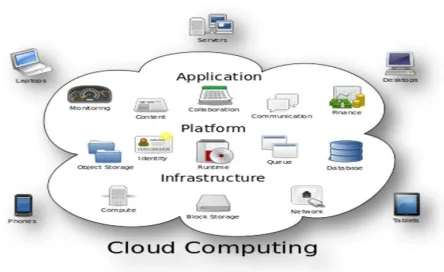
Cloud computing is the use of computing resources (hardware and software) that are delivered as a service over a network (typically the Internet). The name comes from the common use of a cloud-
shaped symbol as an abstraction for the complex infrastructure it contains in system diagrams. Cloud computing entrusts remote services with a user's data, software and computation. Cloud computing consists of hardware and software resources made available on the Internet as managed third-party services. These services typically provide access to advanced software
applications and high-end networks of server computers.
Conference Chair:Prof.Dr.G.ManojSomeswar, Director General, Global Research Academy, Hyderabad, The goal of cloud computing is to apply
traditional supercomputing, or high-performance computing power, normally used by military and research facilities, to perform tens of trillions of computations per second, in consumer-oriented applications such as financial portfolios, to deliver personalized information, to provide data storage or to power large, immersive computer games.[1]
The cloud computing uses networks of large groups of servers typically running low-cost consumer PC technology with specialized connections to spread data-processing chores across them. This shared IT infrastructure contains large pools of systems that are linked together. Often, virtualization techniques are used to maximize the power of cloud computing.
Characteristics and Services Models:
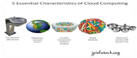
The salient characteristics of cloud computing based on the definitions provided by the National Institute of Standards and Terminology (NIST) are outlined below:
On-demand self-service: A consumer can unilaterally provision computing capabilities, such as server time and network storage, as needed automatically without requiring human interaction with each service’s provider.[2]
Broad network access: Capabilities are available over the network and accessed through standard mechanisms that promote use by heterogeneous thin or thick client platforms (e.g., mobile phones, laptops, and PDAs).
Resource pooling: The provider’s computing
resources are pooled to serve multiple consumers using a multi-tenant model, with different physical and virtual resources dynamically assigned and reassigned according to consumer demand. There is a sense of location-independence in that the customer generally has no control or knowledge over the exact location of the provided resources but may be able to specify location at a higher level of abstraction (e.g., country, state, or data center). Examples of resources include storage, processing, memory, network bandwidth, and virtual machines.[3]
Rapid elasticity: Capabilities can be rapidly and elastically provisioned, in some cases automatically, to quickly scale out and rapidly released to quickly scale in. To the consumer, the capabilities available for provisioning often appear to be unlimited and can be purchased in any quantity at any time.
Measured service: Cloud systems automatically control and optimize resource use by leveraging a metering capability at some level of abstraction appropriate to the type of service (e.g., storage, processing, bandwidth, and active user accounts). Resource usage can be managed, controlled, and reported providing transparency for both the provider and consumer of the utilized service.
Figure 2: Characteristics of cloud computing Services Models:
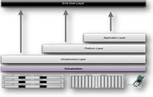
Figure 3: Structure of service models
Benefits of cloud computing:
1. Achieve economies of scale – increase volume output or productivity with fewer people. Your cost per unit, project or product plummets. 2. Reduce spending on technology infrastructure.
Maintain easy access to your information with minimal upfront spending. Pay as you go (weekly, quarterly or yearly), based on demand.[5]
3. Globalize your workforce on the cheap. People worldwide can access the cloud, provided they have an Internet connection.
4. Streamline processes. Get more work done in less time with less people.
5. Reduce capital costs. There’s no need to spend
big money on hardware, software or licensing fees. 6. Improve accessibility. You have access anytime,
anywhere, making your life so much easier! 7. Monitor projects more effectively. Stay within
budget and ahead of completion cycle times. 8. Less personnel training is needed. It takes fewer
people to do more work on a cloud, with a minimal learning curve on hardware and software issues.
9. Minimize licensing new software. Stretch and grow without the need to buy expensive software licenses or programs. [6]
10. Improve flexibility. You can change direction without serious “people” or “financial” issues at stake.
Advantages:
1. Price: Pay for only the resources used.
2. Security: Cloud instances are isolated in the network from other instances for improved security.
3. Performance: Instances can be added instantly for improved performance. Clients have access to the total resources of the Cloud’s core hardware. 4. Scalability: Auto-deploy cloud instances when
needed.
5. Uptime: Uses multiple servers for maximum redundancies. In case of server failure, instances can be automatically created on another server. 6. Control: Able to login from any location. Server
snapshot and a software library lets you deploy custom instances.
7. Traffic: Deals with spike in traffic with quick deployment of additional instances to handle the load.
SYSTEM ANALYSIS
EXISTING SYSTEM
Traffic redundancy stems from common end-users’ activities, such as repeatedly accessing, downloading, uploading (i.e., backup), distributing, and modifying the same or similar information items (documents, data, Web, and video). TRE is used to eliminate the transmission of redundant content and, therefore, to significantly reduce the network cost. In most common TRE solutions, both the sender and the receiver examine and compare signatures of data chunks, parsed according to the data content, prior to their transmission.[7] When redundant chunks are detected, the sender replaces the transmission of each redundant chunk with its strong signature. Commercial TRE solutions are popular at enterprise networks, and involve the deployment of two or more proprietary-protocol, state synchronized middle-boxes at both the intranet entry points of data centers.
DISADVANTAGES OF EXISTING SYSTEM
Conference Chair:Prof.Dr.G.ManojSomeswar, Director General, Global Research Academy, Hyderabad,
The rise of “on-demand” work spaces, meeting rooms, and work-from-home solutions detaches the workers from their offices. In such a dynamic work environment, fixed-point solutions that require a client-side and a server-side middle-box pair become ineffective.
Cloud load balancing and power optimizations may lead to a server-side process and data migration environment, in which TRE solutions that require full synchronization between the server and the client are hard to accomplish or may lose efficiency due to lost synchronization
Current end-to-end solutions also suffer from the requirement to maintain end-to-end synchronization that may result in degraded TRE efficiency.
PROPOSED SYSTEM
In this research paper, we present a novel receiver-based end-to-end TRE solution that relies on the power of predictions to eliminate redundant traffic between the cloud and its end-users. In this solution, each receiver observes the incoming stream and tries to match its chunks with a previously received chunk chain or a chunk chain of a local file. Using the long-term chunks’ metadata information kept locally, the receiver sends to the server predictions that include chunks’ signatures and easy-to-verify hints of the sender’s future data. On the receiver side, we propose a new computationally lightweight chunking (fingerprinting) scheme termed PACK chunking. PACK chunking is a new alternative for Rabin fingerprinting traditionally used by RE applications.
ADVANTAGES OF PROPOSED SYSTEM
Our approach can reach data processing speeds over3 Gb/s, at least 20% faster than Rabin fingerprinting.
The receiver-based TRE solution addresses mobility problems common to quasi-mobile desktop/ laptops computational environments.
One of them is cloud elasticity due to which the servers are dynamically relocated around the
federated cloud, thus causing clients to interact with multiple changing servers.
We implemented, tested, and performed realistic experiments with PACK within a cloud environment. Our experiments demonstrate a cloud cost reduction achieved at a reasonable client effort while gaining additional bandwidth savings at the client side.
Our implementation utilizes the TCP Options field, supporting all TCP-based applications such as Web, video streaming, P2P, e-mail, etc.
We demonstrate that our solution achieves 30% redundancy elimination without significantly affecting the computational effort of the sender, resulting in a 20% reduction of the overall cost to the cloud customer.
INPUT DESIGN
The input design is the link between the information system and the user. It comprises the developing specification and procedures for data preparation and those steps are necessary to put transaction data in to a usable form for processing can be achieved by inspecting the computer to read data from a written or printed document or it can occur by having people keying the data directly into the system. The design of input focuses on controlling the amount of input required, controlling the errors, avoiding delay, avoiding extra steps and keeping the process simple. The input is designed in such a way so that it provides security and ease of use with retaining the privacy. Input Design considered the following things:
What data should be given as input?
How the data should be arranged or coded?
The dialog to guide the operating personnel in providing input.
Methods for preparing input validations and steps to follow when error occur.
OBJECTIVES
design is important to avoid errors in the data input process and show the correct direction to the management for getting correct information from the computerized system.
2. It is achieved by creating user-friendly screens for the data entry to handle large volume of data. The goal of designing input is to make data entry easier and to be free from errors. The data entry screen is designed in such a way that all the data manipulates can be performed. It also provides record viewing facilities.
3.When the data is entered it will check for its validity. Data can be entered with the help of screens. Appropriate messages are provided as when needed so that the user will not be in maize of instant. Thus the objective of input design is to create an input layout that is easy to follow
OUTPUT DESIGN
A quality output is one, which meets the requirements of the end user and presents the information clearly. In any system results of processing are communicated to the users and to other system through outputs. In output design it is determined how the information is to be displaced for immediate need and also the hard copy output. It is the most important and direct source information to the user. Efficient and intelligent output design improves the system’s relationship to help user decision-making.
1. Designing computer output should proceed in an organized, well thought out manner; the right output must be developed while ensuring that each output element is designed so that people will find the system can use easily and effectively. When analysis design computer output, they should Identify the specific output that is needed to meet the requirements.
2.Select methods for presenting information.
3.Create document, report, or other formats that contain information produced by the system.
The output form of an information system should accomplish one or more of the following objectives.
Convey information about past activities, current status or projections of the
Future.
Signal important events, opportunities, problems, or warnings.
Trigger an action.
Confirm an action.
SYSTEM DESIGN
SYSTEM ARCHITECTURE
Figure 4: From Stream to Chain
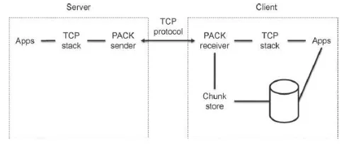
Figure 5: Client Server Architecture DATA FLOW DIAGRAM
1. The DFD is also called as bubble chart. It is a simple graphical formalism that can be used to represent a system in terms of input data to the system, various processing carried out on this data, and the output data is generated by this system. 2. The data flow diagram (DFD) is one of the most
important modeling tools. It is used to model the system components. These components are the system process, the data used by the process, an external entity that interacts with the system and the information flows in the system.
Conference Chair:Prof.Dr.G.ManojSomeswar, Director General, Global Research Academy, Hyderabad, transformations. It is a graphical technique that
depicts information flow and the transformations that are applied as data moves from input to output.
4. DFD is also known as bubble chart. A DFD may be used to represent a system at any level of abstraction. DFD may be partitioned into levels that represent increasing information flow and functional detail.
Figure 6: Data Flow Diagram
UML DIAGRAMS
UML stands for Unified Modeling Language. UML is a standardized general-purpose modeling language in the field of object-oriented software engineering. The standard is managed, and was created by, the Object Management Group.[8]
The goal is for UML to become a common language for creating models of object oriented computer software. In its current form UML is comprised of two major components: a Meta-model and a notation. In the future, some form of method or process may also be added to; or associated with, UML.
The Unified Modeling Language is a standard language for specifying, Visualization, Constructing and documenting the artifacts of software system, as well as for business modeling and other non-software systems.[9]
The UML represents a collection of best engineering practices that have proven successful in the modeling of large and complex systems.
The UML is a very important part of developing objects oriented software and the software development process. The UML uses mostly graphical notations to express the design of software projects.
GOALS:
The Primary goals in the design of the UML are as follows:
1. Provide users a ready-to-use, expressive visual modeling Language so that they can develop and exchange meaningful models.
2. Provide extendibility and specialization mechanisms to extend the core concepts.
3. Be independent of particular programming languages and development process.
4. Provide a formal basis for understanding the modeling language.
5. Encourage the growth of OO tools market.
6. Support higher level development concepts such as collaborations, frameworks, patterns and components.
7. Integrate best practices.
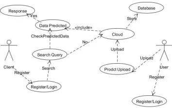
USE CASE DIAGRAM
A use case diagram in the Unified Modeling Language (UML) is a type of behavioral diagram defined by and created from a Use-case analysis. Its purpose is to present a graphical overview of the functionality provided by a system in terms of actors, their goals (represented as use cases), and any dependencies between those use cases.[10] The main purpose of a use case diagram is to show what system functions are performed for which actor. Roles of the actors in the system can be depicted.
Figure 7: Use Case Diagram CLASS DIAGRAM
In software engineering, a class diagram in the Unified Modeling Language (UML) is a type of static structure diagram that describes the structure of a system by showing the system's classes, their attributes, operations (or User
Key generates and encrypts content Upload to cloud
Download encrypt content
Decrypt content
Using Aggregate key Upload Download
methods), and the relationships among the classes. It explains which class contains information.[11]
Figure 8: Class Diagram
SEQUENCE DIAGRAM
A sequence diagram in Unified Modeling Language (UML) is a kind of interaction diagram that shows how processes operate with one another and in what order. It is a construct of a Message Sequence Chart.[12] Sequence diagrams are sometimes called event diagrams, event scenarios, and timing diagrams.
Figure 9: Sequence Diagram
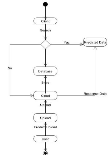
ACTIVITY DIAGRAM
Activity diagrams are graphical representations of workflows of stepwise activities and actions with support for choice, iteration and concurrency.[13] In the Unified Modeling Language, activity diagrams can be used to describe the business and operational step-by-step workflows of components in a system. An activity diagram shows the overall flow of control.
Figure 10: Activity Diagram
Figure 11: Collaborative Diagram
SYSTEM TESTING
Conference Chair:Prof.Dr.G.ManojSomeswar, Director General, Global Research Academy, Hyderabad, TYPES OF TESTS
Unit testing
Unit testing involves the design of test cases that validate that the internal program logic is functioning properly, and that program inputs produce valid outputs. All decision branches and internal code flow should be validated. It is the testing of individual software units of the application .it is done after the completion of an individual unit before integration. This is a structural testing, that relies on knowledge of its construction and is invasive. Unit tests perform basic tests at component level and test a specific business process, application, and/or system configuration. Unit tests ensure that each unique path of a business process performs accurately to the documented specifications and contains clearly defined inputs and expected results.
Integration testing
Integration tests are designed to test integrated software components to determine if they actually run as one program. Testing is event driven and is more concerned with the basic outcome of screens or fields. Integration tests demonstrate that although the components were individually satisfaction, as shown by successfully unit testing, the combination of components is correct and consistent. Integration testing is specifically aimed at exposing the problems that arise from the combination of components.
Functional test
Functional tests provide systematic demonstrations that functions tested are available as specified by the business and technical requirements, system documentation, and user manuals.
Functional testing is centered on the following items:
Valid Input : identified classes of valid input must be accepted.
Invalid Input : identified classes of invalid input must be rejected.
Functions : identified functions must be exercised.
Output : identified classes of application outputs must be exercised.
Systems/Procedures: interfacing systems or procedures must be invoked.
Organization and preparation of functional tests is focused on requirements, key functions, or special test cases. In addition, systematic coverage pertaining to identify Business process flows; data fields, predefined processes, and successive processes must be considered for testing. Before functional testing is complete, additional tests are identified and the effective value of current tests is determined.[15]
System Test
System testing ensures that the entire integrated software system meets requirements. It tests a configuration to ensure known and predictable results. An example of system testing is the configuration oriented system integration test. System testing is based on process descriptions and flows, emphasizing pre-driven process links and integration points.
White Box Testing
White Box Testing is a testing in which in which the software tester has knowledge of the inner workings, structure and language of the software, or at least its purpose. It is purpose. It is used to test areas that cannot be reached from a black box level.
Black Box Testing
Black Box Testing is testing the software without any knowledge of the inner workings, structure or language of the module being tested. Black box tests, as most other kinds of tests, must be written from a definitive source document, such as specification or requirements document, such as specification or requirements document. It is a testing in which the software under test is treated, as a black box .you cannot “see” into it. The test provides inputs and responds to outputs without considering how the software work.
Unit Testing:
Test strategy and approach
Field testing will be performed manually and functional tests will be written in detail.
Test objectives
All field entries must work properly.
Pages must be activated from the identified link. The entry screen, messages and responses must
not be delayed.
Features to be tested
Verify that the entries are of the correct format No duplicate entries should be allowed
All links should take the user to the correct page. Integration Testing
Software integration testing is the incremental integration testing of two or more integrated software components on a single platform to produce failures caused by interface defects.
The task of the integration test is to check that components or software applications, e.g. components in a software system or – one step up – software applications at the company level – interact without error.
Test Results:All the test cases mentioned above passed successfully. No defects encountered.
Acceptance Testing
User Acceptance Testing is a critical phase of any project and requires significant participation by the end user. It also ensures that the system meets the functional requirements.
Test Results: All the test cases mentioned above passed successfully. No defects encountered.
IMPLEMENTATION
MODULES:
1. Data Owner(Alice) 2. Network Storage 3. Aggregate Key Transfer 4. User(Bob)
MODULES DESCRIPTION: Data Owner (Alice):
In this module we executed by the data owner to setup an account on an untrusted server. On input a security level parameter 1λ and the number of ciphertext classes n (i.e., class index should be an integer bounded by 1 and n), it outputs the public system parameter param, which is omitted from the input of the other algorithms for brevity. Network Storage (Drop box):
With our solution, Alice can simply send Bob a single aggregate key via a secure e-mail. Bob can download the encrypted photos from Alice’s Dropbox space and then use this aggregate key to decrypt these encrypted photos. In this Network Storage is untrusted third party server or dropbox.
Aggregate Key Transfer:
A key-aggregate encryption scheme consists of five polynomial-time algorithms as follows. The data owner establishes the public system parameter via Setup and generates a public/master-secret key pair via KeyGen. Messages can be encrypted via Encrypt by anyone who also decides what ciphertext class is asso-ciated with the plaintext message to be encrypted. The data owner can use the master-secret to generate an aggregate decryption key for a set of ciphertext classes via Extract. The generated keys can be passed to delegates securely (via secure e-mails or secure devices) finally; any user with an aggregate key can decrypt any ciphertext provided that the ciphertext’s class is contained in the aggregate key via Decrypt
User (Bob):
The generated keys can be passed to delegates securely (via secure e-mails or secure devices) finally; any user with an aggregate key can decrypt any ciphertext provided that the ciphertext’s class is contained in the aggregate key via Decrypt.
RESULTS & CONCLUSION
Conference Chair:Prof.Dr.G.ManojSomeswar, Director General, Global Research Academy, Hyderabad, REFERENCES
[1] S.S.M. Chow, Y.J. He, L.C.K. Hui, and S.-M. Yiu, “SPICE – Simple Privacy-Preserving Identity-Management for Cloud Environment,” Proc. 10th Int’l Conf. Applied Cryptography and Network Security (ACNS), vol. 7341, pp. 526-543, 2012.
[2] L. Hardesty, Secure Computers Aren’t so Secure. MIT press, http://www.physorg.com/news176107396.html, 2009.
[3] C. Wang, S.S.M. Chow, Q. Wang, K. Ren, and W. Lou, “Privacy-Preserving Public Auditing for Secure Cloud Storage,” IEEE Trans. Computers, vol. 62, no. 2, pp. 362-375, Feb. 2013.
[4] B. Wang, S.S.M. Chow, M. Li, and H. Li, “Storing Shared Data on the Cloud via Security-Mediator,” Proc. IEEE 33rd Int’l Conf. Distributed Computing Systems (ICDCS), 2013.
[5] S.S.M. Chow, C.-K. Chu, X. Huang, J. Zhou, and R.H. Deng, “Dynamic Secure Cloud Storage with Provenance,” Cryptography and Security, pp. 442-464, Springer, 2012.
[6] D. Boneh, C. Gentry, B. Lynn, and H. Shacham, “Aggregate and Verifiably Encrypted Signatures from Bilinear Maps,” Proc. 22nd
Int’l Conf. Theory and Applications of Cryptographic Techniques (EUROCRYPT ’03), pp. 416-432, 2003.
[7] M.J. Atallah, M. Blanton, N. Fazio, and K.B. Frikken, “Dynamic and Efficient Key Management for Access Hierarchies,” ACM Trans. Information and System Security, vol. 12, no. 3, pp. 18:1-18:43, 2009.
[8] J. Benaloh, M. Chase, E. Horvitz, and K. Lauter, “Patient Controlled Encryption: Ensuring Privacy of Electronic Medical Records,” Proc. ACM Workshop Cloud Computing Security (CCSW ’09), pp. 103-114, 2009.
[9] F. Guo, Y. Mu, Z. Chen, and L. Xu, “Multi-Identity Single-Key Decryption without Random Oracles,” Proc. Information Security and Cryptology (Inscrypt ’07), vol. 4990, pp. 384-398, 2007.
[10] V. Goyal, O. Pandey, A. Sahai, and B. Waters, “Attribute-Based Encryption for Fine-Grained Access
Control of Encrypted Data,” Proc. 13th ACM Conf. Computer and Comm. Security (CCS ’06), pp. 89-98, 2006.
[11] S.G. Akl and P.D. Taylor, “Cryptographic Solution to a Problem of Access Control in a Hierarchy,” ACM Trans. Computer Systems, vol. 1, no. 3, pp. 239-248, 1983.
[12] G.C. Chick and S.E. Tavares, “Flexible Access Control with Master Keys,” Proc. Advances in Cryptology (CRYPTO ’89), vol. 435, pp. 316-322, 1989.
[13] W.-G. Tzeng, “A Time-Bound Cryptographic Key Assignment Scheme for Access Control in a Hierarchy,” IEEE Trans. Knowledge and Data Eng., vol. 14, no. 1, pp. 182-188, Jan./Feb. 2002.
[14] G. Ateniese, A.D. Santis, A.L. Ferrara, and B. Masucci, “Provably-Secure Time-Bound Hierarchical Key Assignment Schemes,” J. Cryptology, vol. 25, no. 2, pp. 243-270, 2012.
[15] R.S. Sandhu, “Cryptographic Implementation of a Tree Hierarchy for Access Control,” Information Processing Letters, vol. 27, no. 2, pp. 95-98, 1988.