Design and Simulation of Shunt Active
Power Filter for Harmonic Compensation
Using Fuzzy Logic Controller
Ch. Anusha
M.Tech Student Scholar Department of Electrical & Electronics Engineering, Vignana Bharathi Institute
Of Technology, Ghatkesar; Ranga Reddy; Telangana, India.
Email:anusha.chiruvolu @gmail.com.
Mr. H. Kishan
Assistant Professor Department of Electrical & Electronics Engineering, Vignana Bharathi Institute Of
Technology, Ghatkesar; Ranga Reddy; Telangana, India.
Email:[email protected] @gmail.com.
Abstract-This paper presents a fuzzy logic controlled shunt active power filter used to compensate for harmonic distortion in three-phase four-wire systems. SAPF is one of the key controllers in Flexible Alternating Current Transmission System (FACTS) to control the transmission line voltage and can be used in PS to enhance the power transmission capacity and extend the transient stability. In order to improve the power factor, compensate the reactive power and suppress the total harmonic distortion (THD) drawn from a Non-Linear Diode Rectifier Load (NLDRL) of SAPF, we propose a Hysteresis Current Pulse Width Modulation (HCPWM) technique which is used as control for the switches of the Voltage Source Inverter (VSI) or SAPF. The ability of fuzzy logic to handle rough and unpredictable real world data made it suitable for a wide variety of applications, especially, when the models or processes are too complex to be analyzed by classical methods. In this paper fuzzy logic controller is also used for controlling the DC capacitor voltage. The results show that the proposed controller has fast dynamic response, high accuracy by using MATLAB / SIMULINK are carried out to verify the performance of the proposed controller.
Keywords— Voltage Disturbances, Nonlinear Loads,
PCC, Power Quality, Shunt Active Power Filter
(SAPF), fuzzy logic controller.
I. INTRODUCTION
Harmonics are one of the major concerns in a power system. Harmonics cause distortion in current and voltage waveforms resulting into deterioration of the power system. The first step for harmonic analysis is the harmonics from on-linear loads. The results of such analysis are complex. Over many years, much importance is given to the methods of analysis and control of harmonics. Harmonics present in power system also has non-integer multiples of the fundamental frequency and have a periodic waveform. The harmonics are generated in a power system from two distinct types of loads. First category of loads is described as linear loads [1-2]. The linear time-invariant loads are characterized such that application of sinusoidal voltage results in sinusoidal flow of current. on-linear loads are considered as the second category of loads. The application of sinusoidal voltage does not result in a sinusoidal flow applied sinusoidal voltage for non-linear devices. Harmonic current is isolated by using harmonic filters in order to protect the electrical equipment from getting damaged due to harmonic voltage distortion. They can also be used to improve the power factor.
reliable and efficient operation of overall network. With the advancement in power electronics and digital control technology, the DG systems can now be actively controlled to enhance the system operation with improved PQ at PCC. However, the extensive uses of power electronics based incorporating PQ solution have been proposed. In [3] an inverter operates as active inductor at a certain frequency to absorb the harmonic current. But the exact calculation of network inductance in real-time is difficult and may deteriorate the control performance.
With the advancement in power electronics and digital control technology, the DG systems can now be actively controlled to enhance the system operation with improved PQ at PCC. However, the extensive use of power electronics based equipment and non-linear loads at PCC[3]-[5] generate harmonic currents, which may deteriorate the quality of power. The widespread increase of non-linear loads nowadays, significant amounts of harmonic currents is being injected into power systems. Harmonic currents flow through the power system impedance, causing voltage distortion at the harmonic currents‟ frequencies. The distorted voltage waveform causes harmonic currents to be drawn by other loads connected at the point of common coupling (PCC). The advantages of fuzzy logic controllers over the conventional PI controller are that they do not need an accurate mathematical model; they can work with imprecise inputs, can handle nonlinearity, and may be more robust than the conventional PI controller. Use of fuzzy logic for minimization of harmonics and improvement of power quality is not a new issue rather various authors have introduced some innovative methodologies using these tools[5]. The most important observation from the work reported by various researchers for power quality improvement is the Design of active power filter under „fixed load‟ conditions or for loads with slow and small variation [6]. As loads in practical life are mostly variable, there is the need to design an active power filter, which is capable of maintaining the THD well within the IEEE norms [7], under variable load conditions.
Fig. 1 shows the basic compensation principle of the three phase shunt APF. It is designed to be connected in parallel with the nonlinear load to detect its harmonic and reactive current and to inject into the system a compensating current. In the conventional p-theory based control approach for the shunt APF, the compensation current references are generated based on the measurement of load currents. However, the current feedback from the SAPF output is also required and therefore, minimum six CSs are desired in a unbalanced system. In addition, the reference current calculation algorithm are simplified and easily implemented in the experimental prototype. In the reduced current measurement control algorithm, sensing only three-phase voltages, three source currents and a DC-link voltage is adequate to compute reference currents of the threephaseSAPF. In this way, the overall system design becomes easier to accomplish and the total implementation cost is reduced.
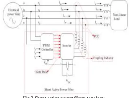
Fig.2.Shunt active power filters topology.
II. VOLTAGE SOURCE CONVERTERS
Fig.3.Principle of Shunt Current Compensation.
Voltage source converters are preferred over current source converter because it has higher efficiency and lower initial cost than the current source converters [3, 4, 9]. They can be readily expanded in parallel to increase their combined rating and their switching rate can be increased if they are carefully controlled so that their individual switching times do not coincide. Therefore, higher-order harmonics can be eliminated by using converters without increasing individual converter switching rates. Because of non linear load current will have harmonics, so load current will be the summation of fundamental and all other harmonics, all harmonics will be integer multiple of fundamental frequency. Load current can be written as
(1)
Instantaneous Load can be written as
(2)
Putting value of iL(t) from equation (1) in equation (2)
(3)
Here PA(t) is active or fundamental power. Only
fundamental component of voltage and current can deliver power to the load and PR(t) is reactive power. Harmonic
power denoted by PH(t). So active or real power drawn by
the load from the source is
(4)
Therefore, source current after compensation will be given by equation (5)
(5)
Where
In a practical converter, there are switching, conducting and capacitor leakage losses. So that losses must be
supplied by the supply or by the grid itself. So total current supplied by supply will be given as
(6) Where isp= peak current supplied by source. whereas =
loss current of converter supplied by the source.
If total harmonic and reactive power of the load is supplied, by the Active Power Filter then there will not be any harmonic in source current and source current will be in phase with the source voltage. Therefore, the total source current including losses will be given as 𝑖𝑠∗ 𝑡 =
𝑖𝑠𝑝𝑠𝑖𝑛𝜔𝑡So compensating current will be given as
(7) It is obvious from above discussion that for instantaneous compensation of reactive power in addition, harmonic power, source (grid) should be able to supply current𝑖𝑠∗ 𝑡 . Therefore, it is necessary to find 𝑖𝑠∗ 𝑡 which is known as reference current.
III.ESTIMATION OF REFERENCE SOURCE CURRENT
The instantaneous currents can be written as
(8)
Source voltage is given by
(9)
If a non-linear load is applied, then the load current will have a fundamental component and harmonic components which can be represented as
(10)
(11) The instantaneous load power can be given as
(12) From the real (fundamental) power drawn by the load is
(13)
(14) Where Ism=I1cosΦ1.
There are also some switching losses in the PWM converter, and hence the utility must supply a small overhead for the capacitor leakage and converter switching losses in addition to the real power of the load. The total peak current supplied by the source is therefore
(15) If the active filter provides the total reactive and harmonic power, then is(t) will be in phase with the utility voltage and purely sinusoidal. At this time, the active filter must provide the following compensation current:
(16) Hence, for accurate and instantaneous compensation of reactive and harmonic power it is necessary to estimate, i.e. the fundamental component of the load current as the reference current. The design of the power circuit includes three main parameters: Lc, Vdc, ref and Cdc.
A. SELECTION OF Lc, Vdc,ref and Cdc
The design of these components is based on the following assumptions:
The AC source voltage is sinusoidal.
To design of Lc, the AC side line current distortion is assumed to be 5%.
Fixed capability of reactive power compensation of the active filter.
The PWM converter is assumed to operate in the linear modulation mode (i.e. 0≤ma≤1).
As per the compensation principle, the active filter adjusts the current ic1 to compensate the reactive power of the load [2]. If the active filter compensates all the fundamental reactive power of the load, is1 will be in phase and ic1 should be orthogonal to Vs. The three-phase reactive power delivered from the active filter can be calculated from a vector diagram
(17) i.e. the active filter can compensate the reactive power from the utility only when Vc1 > Vs.If the PWM converter is assumed to operate in the linear modulation mode (i.e. 0≤ma≤1), the amplitude modulation factor ma is
(18) Where vm=√2 Vc, and hence Vdc = 2√2 Vc1 for ma=1. The
filter inductor Lc is also used to filter the ripples of the converter current, and hence the design of Lc is based on
current of the PWM converter can be given in terms of the maximum harmonic voltage, which occurs at the frequency mfω:
(19)
IV. PI CONTROL SCHEME
Fig.4 APF Control scheme with PI controller.
The error signal is fed to PI controller. The output of PI controller has been considered as peak value of the reference current. It is further multiplied by the unit sine vectors (usa, usb, and usc) in phase with the source voltages to obtain the reference currents (isa*, isb*, and isc*).
These reference currents and actual currents are given to a hysteresis based, carrier less PWM current controller to generate switching signals of the PWM converter [5]. The difference of current template and actual current decides the operation of switches. These switching signals after proper isolation and amplification are given to the switching devices. Due to these switching actions current flows through the filter inductor Lc, to compensate the harmonic current and reactive power of the load, so that only active power drawn from the source.
V. FUZZY LOGICCONTROLLER
definitions and the control rule set; a decision-making logic which, simulating a human decision process, infer the fuzzy control action from the knowledge of the control rules and linguistic variable definitions; a de-fuzzification interface which yields non fuzzy control action from an inferred fuzzy control action [10].
Fig.5. General Structure of the fuzzy logic controller. The fuzzy control systems are based on expert knowledge that converts the human linguistic concepts into an automatic control strategy without any complicated mathematical model [10]..
Fig.6. Block diagram of the Fuzzy Logic Controller (FLC)for proposed converter.
Fig.7. Hysteresis current Modulation
With the hysteresis control, limit bands are set on either side of a signal representing the desired output waveform [6]. The inverter switches are operated as the generated signals within limits. The control circuit generates the sine reference signal wave of desired magnitude and frequency,
and it is compared with the actual signal. As the signal exceeds a prescribed hysteresis band, the upper switch in the half bridge is turned OFF and the lower switch is turned ON. As the signal crosses the lower limit, the lower switch is turned OFF and the upper switch is turned ON. The actual signal wave is thus forced to track the sine reference wave within the hysteresis band limits.
VI.MATLAB/SIMULATIONS RESULTS
Here, the simulation results presented in different cases:
case1: without APF
case2: with APF and PI controller. case3: with APF and fuzzy logic controller. Case1: without APF
Fig.8.Matlab/Simulink Model of without Shunt active power filters topology with PI controller.
Fig.13.source voltage,source current and load current without APF
Fig.11. source current THD for without APF.
Case2: with APF and PI controller
Fig.12.Matlab/Simulink Model of with Shunt active power filters topology with PI controller.
Fig.13.source voltage,source current and load current with PI controller.
Fig.14.Source Voltage and Current are in Phase Using PI Controller.
Fig.15. source current THD for PI controller.
Case3: with APF and fuzzy logic controller.
Fig.16.Matlab/Simulink Model of control diagram for Shunt active power filters topology with fuzzy logic controller.
Fig.17.source current, load current,inverter current and source voltage with fuzzy logic controller.
Fig.19.source current THD for fuzzy logic controller.
VII. CONCLUSION
PI and Fuzzy controller based shunt active power filter simulated n MATLAB are implemented for harmonic and reactive power compensation of the non-linear load at PCC. It is found from the simulation results that shunt active power filter improves power quality of the distribution system by eliminating harmonics and reactive power compensation of non-linear load. The Source current THD is 1.87% for PI controller and 0.22% for fuzzy controller. So we conclude that fuzzy controller has the better performance compared to PI controller. The HCPWM control has successfully eliminated the harmonics and improved the power factor in supply side. The simulation results show the efficiency of the fuzzy logic controller in maintaining the DC voltage set point. Future work, the neuro control technique can be applied to study the proposed system further
REFERENCES
[1] C.-S. Lam, M.-C.Wong Y.-D. Han, “Hysteresis current control of hybrid active power filters” Published in IET Power Electronics, doi: 10.1049/iet-pel.2011.0300
[2] VinodKhadkikar, “Enhancing Electric Power Quality Using UPQC:A Comprehensive Overview” IEEE Transactions on Power Electronics, Vol. 27, No. 5, May 2012
[3] S. Orts-Grau, F. J. Gimeno-Sales, A. Abellán-García, S. Seguí- Chilet, and J. C. Alfonso-Gil, “Improved Shunt Active Power Compensator for IEEE Standard 1459 Compliance” IEEE Transactions on Power Delivery, Vol. 25, No. 4, October 2010
[4] Reyes S. Herrera and Patricio Salmerón, “Instantaneous Reactive Power Theory: A Comparative Evaluation of Different Formulations” IEEE Transactions On Power Delivery, Vol. 22, No. 1, January 2007
[5] Reyes S. Herrera, Patricio Salmerón, and Hyosung Kim, “Instantaneous Reactive Power Theory Applied to
Active Power Filter Compensation: Different Approaches, Assessment, and Experimental Results” IEEE Transactions On Industrial Electronics, Vol. 55, No. 1, January 2008
[6] Yunwei Li, D. MahindaVilathgamuwa and Poh Chiang Loh, “Microgrid Power Quality Enhancement Using a Three-Phase Four-Wire Grid-Interfacing Compensator” IEEE Transactions On Industry Applications, Vol. 41, No. 6, November/December 2005.
[7] A.Elmitwally, SAbdelkader and M.EI-Kateb, “Neural network controlled three-phase four-wire shunt active power filter” IEE Power Generation & transmission Vol. 147, N0.2 March 2000
[8] J. A. Barrado, R. Griñó and H. Valderrama-Blavi, “Power-Quality Improvement of a Stand-Alone Induction Generator Using a STATCOM With Battery Energy Storage System” IEEE Transactions On Power Delivery, Vol. 25, No. 4, October 2010.
[9] Rade M. Ciric, Antonio PadilhaFeltrin, and Luis F. Ochoa, “Power Flow in Four-Wire Distribution Networks—General Approach” IEEE Transactions On Power Systems , Vol. 18, No. 4,November 2003.
[10] P. Salmerón, J. C. Montaño, J. R. Vázquez, J. Prieto, and A. Pérez, “Compensation in Non-sinusoidal, Unbalanced Three-Phase FourWire Systems With Active Power-Line Conditioner” IEE Transactions On Power Delivery, Vol. 19, No. 4, October 2004.
Mr H.KISHAN was graduated in 2006 from Jyothishmathi Institute Of Technology And Science Karimnagar affiliated to
JNTU-HYD in Electrical and Electronics
Engineering. He took his post graduate degree in 2010 from Ramappa Engineering College Warangal affiliated to JNTU-HYD in power systems. His research interest in
Load frequency control, Distribution
systems and Renewable energy resources.
CH.ANUSHA was graduated in 2012 in
first class with distinction from Hyderabad