RESEARCH
Open Access
Effects analysis of imperfections on multi-antenna
transceiving systems
Huiyong Li, Qi An
*, Kexin Jia, Hao Wu and Zishu He
Abstract
Multi-antenna transceiving systems are widely used in high speed wireless communications due to its higher efficiency comparing to its traditional single-antenna counterparts. In this article, the performance effects of some inevitable imperfections are elaborated on multi-antenna transceiving systems. The simulation results are also displayed. An effective method for phase noise elimination is presented and validated using simulation examples.
1. Multi-antenna technology scheme
With the growing development of wireless communica-tions in the current society, the conflict between the ever-increasing service requirements of wireless commu-nications and the resource limitation of radio spectrum becomes increasingly apparent [1,2]. A key technology to solve this problem is multi-antenna techniques, which can enhance the frequency efficiency and link reliability drastically. Compared to the single-antenna communication systems, array gain (i.e., beam forming gain), diversity gain, multiplexing gain, and interference suppression can be obtained by using the multi-antenna communication systems.
In recent communication systems, two of the primary multi-antenna techniques are multi-input multi-output (MIMO) and transceiving beamforming.
MIMO [3,4], which is developed based on the smart antenna technology, has its distinct superiority. In the MIMO systems, the wireless channels are independent, or weakly correlated. Due to its abundant multi-paths, MIMO systems could enhance the system capability greatly [5].
The signal processing flow on transceiving beamform-ing is simple and apt to hardware applications because it does not involve so much prior knowledge and any
complicated algorithm. However, the channels’
consis-tency is so rigorous in demand. Thanks to the narrow beam, the performance will be decrease sharply if any direction error exists.
According to these disadvantages, some inevitable imperfections will be discussed from four different aspects. In the following section, lots of closed-form expressions are derived and verified by the simulation results subsequently.
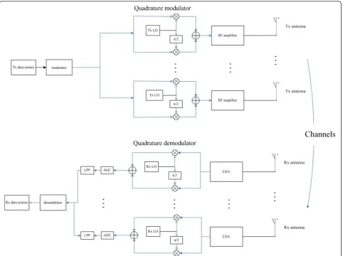
2. Effects analysis of imperfect factors
Considering anN×Ntransceiving beam formation
sys-tem, there are also lots of imperfect elements even if the beams between transmitting and receiving ends are com-pletely in the right direction. Some of these unsatisfactory factors such as narrowband or wideband amplitude and phase error, the amplitude and phase error in in-phase (I) channel, quadrature (Q) channel, and phase noise, are focused in this article. Each of them is added into the ideal model and discussed, respectively (Figure 1).
2.1. Narrowband amplitude and phase error
In this study, we consider the case where the amplitude and phase error in the signal path are narrowband. Denote the output signal of filter in each transmitting
path by s(t), and the output of the mth (m = 1,..., N)
transmitting channel with error by gmejφm. Then the
output of every transmitting antenna can be written as
gmejφm·s(t), wheregm= 1-sm,smis random and
expo-nentially distributed, andjmis uniformly distributed in
the range of [0,θ]. The nth(n= 1,...,N) channel noise is
denoted bynn(t). If the amplitude and phase error exists
in each signal path at both the transmitting and receiv-ing ends, which are expressed as gmejφm and hnejϕn
respectively, the total signal received will be
* Correspondence: [email protected]
School of Electronic Engineering, University of Electronic Science and Technology of China, Chengdu, China
Liet al.EURASIP Journal on Wireless Communications and Networking2012,2012:81 http://jwcn.eurasipjournals.com/content/2012/1/81
N
In the multi-antenna transceiving systems, the coun-terparts of signal-to-noise ratio in single-antenna sys-tems (SNR) will be updated to
SNR=
2.2 Wideband amplitude and phase error
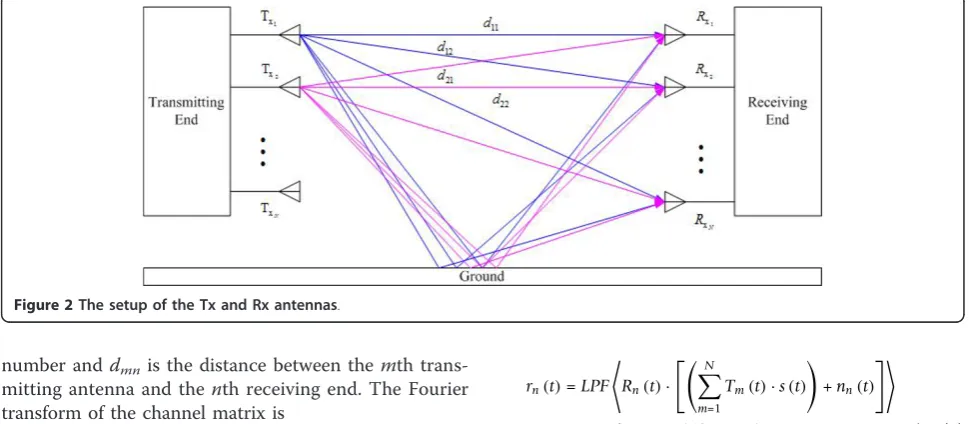
When wideband amplitude and phase error is consid-ered, the signal propogation channel is considered as a matrix [6]:
where hmnrepresents the amplitude fading and phase
difference between themth transmitting antenna and the
nth receiving antenna (Figure 2).
After considering the multi-path transmission, hmn
varies with time and can be modeled as [7]
hmn(t)=δ (t)ejkdmn+bδ (t−τ)ejφmn (5)
where b is the relative amplitude fading,τ is the
coun-ter-shifting, jis the relative phase, k= 2π
λ is the wave
number anddmnis the distance between the mth
trans-mitting antenna and the nth receiving end. The Fourier
transform of the channel matrix is
H(ω)=
Thus, the channel’s total power can be computed as
P=
The received signal vector can be expressed as
⎡
2.3. Amplitude and phase error in in-phase and quadrature channels
The procedure of extracting the in-phase and quadra-ture parts and up-converting brings amplitude and phase error to the receiving signal. The errors in the transmitting and receiving ends have similar expressions, which are modeled [8] as: Tm(t) = 2[km cos(ωt), sin(ωt
+m)] andRn(t) = [lncos (ωt), sin(ωt+gn)]. The kmand
ln (m,n = 1,...,N) represent the amplitude errors and
they are both in the range of [1-ξ,1+ξ], whereξis a tiny
number. The phase errors and g are assumed to be
much less than π
2. After the low-pass filtering, the
received signal of thenth path is
rn(t)=LPF
where Hn represents thenth channel matrix of I/Q
channel and is defined as
Hn=LPF
The sum of the signal from allNchannels is
r(t)=
2.4. The model and correction of phase noise
For both the single-antenna and multi-antenna systems, local oscillator (LO) will bring phase noise inevitably. Usually, the phase noise is assumed to obey the white Gaussian noise model, colored Gaussian noise model, or Wiener model [7,9-11]. Here we consider the Wiener
model and denotes the phase noise for the kth symbol
byejk. The discrete form of phase noise can be written as
ϕ (k)=α·ϕ (k−1)+ϕ (9)
Figure 2The setup of the Tx and Rx antennas.
Liet al.EURASIP Journal on Wireless Communications and Networking2012,2012:81 http://jwcn.eurasipjournals.com/content/2012/1/81
where Δobeys the normal distribution and is
ran-dom generated, that is, Δ~N(0,s2), σ2= 4πf3dB
Fs
,
fΔ3dB is the 3 dB line width, Fs is the sampling
fre-quency, ais a constant near but less than 1. The
rela-tional expression displayed in (9) indicates that the current phase noise is related with its previous moment, which is different to the two other counterparts. Assumed that s(t) is the output signal in each transmit-ting path and all the transmitted signals can be received by every receiving antenna. The sampled received signal in thenth path can be written as
rn(k)=
N·s(k)+nn(k)
ejϕn(k) (11)
whereNdenotes the number of antennas which is the
same for both the transmitting and receiving ends. The
sum of received signals is equivalent to N2 times the
transmitting signal in the ideal case. Then the error can be expressed as
e(k)=
1
N2 N
n=1
rn(k)
−s(k)
=
1
N2 N
n=1
(N·s(k)+nn(k))·ejϕn(k)
−s(k)
=s(k)·
1
N N
n=1
ejϕn(k)
−1
+ 1
N2 N
n=1
nn(k)·ejϕn(k) (12)
Thanks to the especial character, a few approaches are derived to eliminate the errore(n). Gitlin [12] modeled the phase noise as sinusoidal signal and presented self-adaptation and compensation method named finite impulse response-adaptive line enhancer (FIR-ALE).
However, the ability of compensation is limited. Another method, the infinite impulse response-adaptive line enhancer (IIR-ALE) [13] has obvious effect provided many prior information being known. extended Kalman filter (EKF) [14] is used to estimate phase noise by line-arizing first order digital phase locked loop (DPLL), in which, however, the non-convergent condition happens sometimes.
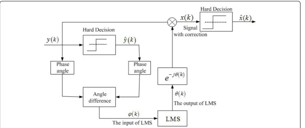
In this article a more accurate method is adopted which is called angle-offset least mean square (AO-LMS). As shown in Figure 3, the angle difference between input signal and its hard-decision results is
Figure 3Algorithm structure of AO-LMS.
used as the input of LMS to estimate the real phase noise.
As an improvement approach to FIR-ALE, the input of LMS algorithm is a more accurate input, which is closer to the real phase offset caused by phase noise. It means a clearer aim and a better compensation ability.
2.5 Simulation results
The four errors introduced above are simulated. We consider a 64-ary QAM multi-antenna system. The transmitting and receiving ends each has 4 antennas.
The sampling rate isfs= 4 MHz. Rooted raised cosine
(RRC) filters are adopted in both the transmitting and receiving ends. The roll-off factor isa = 0.02. The rate of sampling period and symbol period is 2, and the order of RRC is 16. The effects of different factors on the transceiving performance are shown in Figures 4, 5, and 6. As is shown in Figure 4, symbol error rate (SER) gets a sharply increase when the narrowband phase error starts rising. Comparatively, the amplitude error puts a much less influence on it. Figure 5 displays the effect of wideband amplitude and phase error. When the channel fading is small (i.e., b1 = 0.01), the situation is very similar to the ideal case. However, just a little increase of the fading can lead to the rapid rise of SER much less a large value near 1. The amplitude and phase error caused in I/Q channels are measured by another criteria error vector magnitude (EVM) as it is shown in Figure 6. Yet the amplitude error and phase error both have a drastic influence on the transceiver’s performance.
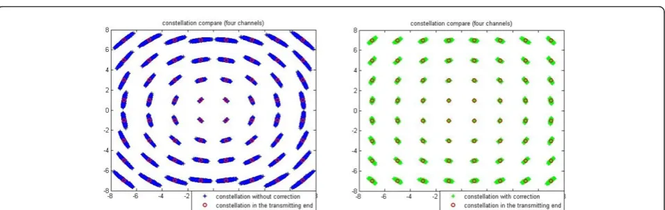
The following simulation results verify the compensa-tion ability of AO-LMS. Constellacompensa-tion before and behind the block of phase noise compensation are shown in Figures 7 and 8. In the view of constellation, the signal with phase noise brings a circular change along the amplitude circles. It is distinctly presented when SNR is large enough. Figure 8 shows that the algorithm adopted can take an apparent clustering even if large Gaussian channel noise exists. On the other hand, as is shown in
Figure 5SER analysis with wideband amplitude and phase error.
Figure 6EVM analysis with I/Q amplitude and phase error.
Figure 7Constellations without and with phase noise compensation (SNR = 15 dB).
Liet al.EURASIP Journal on Wireless Communications and Networking2012,2012:81 http://jwcn.eurasipjournals.com/content/2012/1/81
Figure 9, the symbol error number can decrease sharply to less than one-tenth compared to the number before correction and at least one order of the SNR (dB) is got-ten. Furthermore, the algorithm is adapted to engineer-ing application due to its less tap number. The tap number used in the simulation is 16.
3. Conclusion
Aiming at analyzing the transceiving beam forming sys-tems, some imperfect factors are considered and ana-lyzed theoretically. Phase noise is presented as a more inevitable factor. An effective compensation method is presented and verified by simulation results.
Acknowledgements
The authors would like to thank the support of Fundamental Research Funds for the Central Universities (ZYGX2010J015).
Competing interests
The authors declare that they have no competing interests.
Received: 28 September 2011 Accepted: 5 March 2012 Published: 5 March 2012
References
1. AJ Paulraj, RU Nabar, DA Gore, Introduction to space-time wireless communications [M], (Cambridge University Press, Cambridge, 2002) 2. X Liu, LT Yang, K Sohn, High-Speed Inter-view Frame Mode Decision
Procedure for Multi-view Video Coding, Future Generation Computer Systems (Elsevier), May 2011, doi:10.1016/j.future.2011.05.013
3. D Gesbert, M Shafi, From theory to practice: an overview of MIMO space-time coded wireless systems. IEEE J Sel AreasCommun.21(3), 281–302 (2003). doi:10.1109/JSAC.2003.809458
4. A Goldsmith, SA Jafar, N Jindal, S Vishwanath, Capacity limits of MIMO channels. IEEE J Sel Areas Commun.21(5), 684–702 (2003). doi:10.1109/ JSAC.2003.810294
5. Q He, RS Blum, AM Haimovich, Non-coherent MIMO radar for location and velocity estimation: more antennas means better performance. IEEE Trans Signal Process.58(7), 3661–3680 (2010)
6. T Ingason, H Liu, M Coldrey, A Wolfgang, J Hansryd, Impact of frequency selective channels on a line-of-sight MIMO microwave radio link. Vehicular Technology Conference (VTC 2010-Spring) 1–5 (2010)
7. A Georgiadis, Gain, phase imbalance, and phase noise effects on error vector magnitude. IEEE Trans Veh Technol.53(2), 443–449 (2004). doi:10.1109/TVT.2004.823477
8. Z Chen, FF Dai, Effects of LO phase and amplitude imbalances and phase noise on M-QAM transceiver performance. IEEE Trans Indust Electron.57(5), 1505–1517 (2010)
9. NJeremy Kasdin, Discrete simulation of colored noise and stochastic processes and 1/fαpower law noise generation. Proc IEEE.83(5), 802–827 (1995). doi:10.1109/5.381848
10. S Berger, A Wittneben, Comparison of channel estimation protocols for coherent AF relaying networking in the presence of additive noise and LO phase noise. EURASIP J Wirel Commun Netw.2010(2010)
11. A Georgiadis, Gain, phase imbalance, and phase noise effects on error vector magnitude. IEEE Trans Veh Technol.53(2), 443–449 (2004). doi:10.1109/TVT.2004.823477
12. S Wu, P Liu, Y Bar-Ness, Phase noise estimation and mitigation for OFDM systems. IEEE Trans Wirel Commun.5(12), 3616–3625 (2006)
13. MR Gholami, S Nader-Esfahani, AA Eftekhar, A new method of phase noise compensation in OFDM. IEEE International Conference on Communications (ICC‘03)3443–3446. Vol.5, Issue Date 11-15 May 2003
14. B Farhang-Boroujeny, Pre-equaliser cancellation of sinusoidal phase jitter. IEE Proc Commun.142(4), 216–220 (1995). doi:10.1049/ip-com:19952054
doi:10.1186/1687-1499-2012-81
Cite this article as:Liet al.:Effects analysis of imperfections on multi-antenna transceiving systems.EURASIP Journal on Wireless
Communications and Networking20122012:81. Figure 8Constellations without and with phase noise compensation (SNR = 7 dB).