Development
and
characterization
of
a
flux-pumped
lumped element Josephson parametric amplifier
MartinaEsposito1,∗,JosephRahamim1,AndrewPatterson1,MatthiasMergenthaler1,James Wills1, Giulio Campanaro1, Takahiro Tsunoda1, Peter Spring1, Sophia Sosnina1, Salha Jebari1,KittyRatter1,GiovannaTancredi1,BrianVlastakis1, andPeterLeek1
1Clarendon Laboratory, Department of Physics, University of Oxford, OX1 3PU, United Kingdom
Abstract.Josephson parametric amplification is a tool of paramount impor-tance in circuit-QED especially for the quantum-noise-limited single-shot read-out of superconducting qubits. We developed a Josephson parametric amplifier (JPA) based on a lumped-element LC resonator, in which the inductance L is composed by a geometric inductance and an array of 4 superconducting quan-tum interference devices (SQUIDs). We characterized the main figures of merit of the device, obtaining a−3 dB bandwidthBW=15 MHz for a gainG=21 dB and a 1 dB compression pointP1dB = −115 dBm. The obtained results are promising for the future use of such JPA as the first stage of amplification for single-shot readout of superconducting qubits.
1 Introduction
Josephson parametric amplification has received growing attention in the last decade in the field of circuit quantum electrodynamics (circuit-QED) [1–3] becoming a fundamental tool in superconducting quantum information research [4–14]. By parametrically modulating the in-ductance of one or more Josephson junctions, it is possible to amplify an incoming microwave signal by adding only the minimum amount of noise allowed by quantum mechanics. The major application of this is single-shot readout of superconducting qubits [15].
The mechanism of Josephson parametric amplification can be described in complete analogy to the one of optical parametric amplification, routinely used in laser laboratories [16, 17]. In optics, the refractive index of a non-linear crystal is parametrically modulated in time with a pump field at frequencyωpin order to amplify an input optical signal at frequencyωs, with the creation of an idler field at frequencyωi. Analogously, in superconducting circuits, the non-linear inductance of one or more Josephson junctions is parametrically modulated with a pump field in order to amplify an input signal in the microwave regime, by creating an additional idler field through a wave-mixing process.
The gain process in Josephson parametric amplification can be enhanced by using essentially two approaches; the first consists in embedding the Josephson non-linear elements in a mi-crowave resonator which works in reflection and defines the bandwidth of operation of the amplifier (resonant-JPA) [4–11]; the second approach instead uses a very large number (typ-ically hundreds) of Josephson elements in a long microwave coplanar wave guide working in
(2ωp = ωs+ωi) due to the fact that the inductanceL is proportional to the square of the driving pump current [20]. On the other hand, in flux-pumped JPAs, one or more supercon-ducting quantum interference devices (SQUIDs) are embedded in the resonator; in this case the inductance can be modulated by varying the magnetic flux threading the SQUID loops, generating this time a three-wave-mixing process (ωp=ωs+ωi) because the inductance L is directly proportional to the driving current [20]. This last approach has been demonstrated in several labs [6–8, 10] and has the advantage that the pump signal doesn’t travel through the resonator but it goes through a distinct flux-line, avoiding in this way any noise-contributions from the pump to the amplified signal.
We developed a flux-pumped JPA based on a well established design [10] developed in the Quantronics lab in Saclay, with the target to obtain 20 dB of gain and a minimum band-width of 10MHz. The main difference from the Saclay design is the operational frequency range (our JPA is tunable in the 8-10 GHz range, while the one in [10] works in the 4-6 GHz range). These paremeters have been chosen in order to use the JPA, in future experiments, as first stage of amplification for the readout of a superconducting qubit based on a coaxial architecture recently developed in our lab in Oxford [23]. The basic unit of this architecture is made of a superconducting qubit and a linear resonator which are placed on the two oppo-site sides of a single chip, allowing out-of-plane readout and easy scalability to large arrays of qubits [23]. We configured the JPA design in order to obtain gain in the frequency range (8-10 GHz) which correspond to the resonant frequency of our coaxial linear resonator [23]. In the following, the fabrication details and the characterization measurements of the devel-oped JPA are shown.
2 Circuit design and fabrication parameters
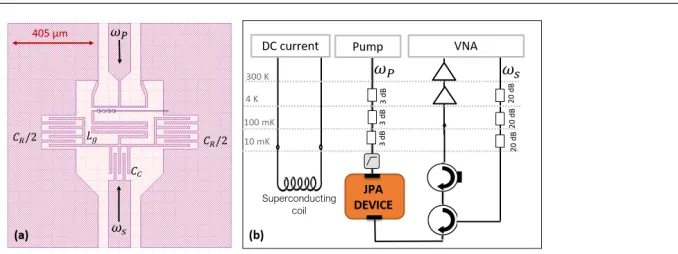
The design of the JPA is shown in figure 1-(a). The LC resonator is made of a capacitance CR = 275 fF, composed by two interdigitated capacitors, and an inductanceL, composed by a meander of inductanceLg =0.27 nH and an array of 4 SQUIDs of inductanceLA. Fi-nally a 50Ωcoplanar wave guide is coupled to the resonator by an interdigitated coupling capacitor of capacitanceCC = 36 fF. The resonance frequency can thus be expressed as
fR =1/p(Lg+LA)(CC+CR).
The device has been fabricated through a single-step electron beam lithography on a 5×5×
0.5 mm sapphire chip, pattering the whole structure by evaporating a 100 nm aluminum layer. The SQUIDs, composed by a 8µm×11µm superconducting loop with two identical junctions
with nominal area of 1.8µm2, have been fabricated with a double-angle evaporation tech-nique. The measured room-temperature resistance of a single SQUID isRSQUID=100±10Ω, from which we infer the single-junction critical currentIC=2.7±0.1µA.
Figure 1. (a) CAD design of the JPA circuit. The coloured part indicates the aluminum layer and the white part indicates the sapphire substrate. A 50Ωcoplanar wave guide, where theωssignal travels,
is coupled to an LC resonator via a coupling capacitorCc. The capacitance of the resonator is given byCRand the inductance is given by the geometric inductanceLgand the Josephson inductance of an array of 4 SQUIDs shorted to ground. The pump signal, at frequencyωpis sent through a flux line that
is distant 15µmfrom the SQUIDs. (b) Schematic drawing of the cryogenic experimental set-up.
OnceLJ1is known, it is possible to estimate two important parameters for the JPA. The first one is the single SQUIDβparameter [24], which takes into account the finite loop inductance of each SQUID and is defined asβ=Lloop/LJ1. It is desirable to keep this parameter low in order to avoid hysteresis problems of the SQUIDs [24, 25]. In our case, estimating the loop inductance as 1 nH perµm, we obtainβ=0.30±0.01.
The second important parameter is the so called participation ratio of the Josephson induc-tance LJ, which is defined as p = LJ/L, where L is the total inductance. In detail, the Josephson inductance can be expressed as follows [10],
LJ= N
2
LJ1
cosx+β2sin2x, (1)
where N indicates the number of SQUIDs andx=πΦ/Φ0, withΦthe applied magnetic flux. On the other hand, the total inductance is,
L=Lg+LA, where LA= β
4NLJ1+LJ. (2)
Using the above expressions (full derivation in [10]) we can estimate the participation ratio, obtaining in our case p = LJ/L = 0.44±0.1. It is also desirable to keep the pparameter low because it quantifies the Kerr non-linearity of the resonator [9], that, in flux-pumped JPA, should be kept low since it leads to saturation effects of the gain reducing the dynamic range [9–11]. It should be noticed that another way to decrease the Kerr non-linearity and increase the dynamic range of the amplifier is to increase the number of SQUIDs in the array [9, 10].
3 JPA characterization measurements
In this section we present the results of the JPA characterization measurements; in particular we show the characterization of the resonance frequency as a function of the DC flux, the gain-bandwidth characterization and the dynamic range characterization.
Φ = ΦDC+ ΦACcos (ωpt+χ), (3)
whereωpis the pump frequency andχa phase offset.
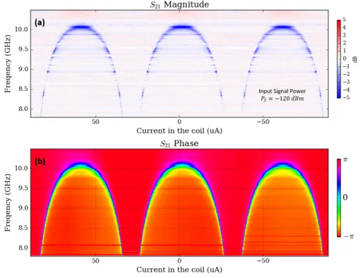
In figure 2 we show the measurement of the resonance frequency fRas a function ofΦDC, for
ΦAC =0.
Figure 2.Magnitude (a) and phase (b) of the VNA scattering parameterS21for a reflection measure-ment of the JPA device as a function of the current sent into the superconducting coil (x-axis) and of input frequency (y-axis).
For each fixed current value we can estimate the resonance frequency fRand the quality factorQby fitting the phase data with a functiong(f)=−2 arctan (2Q(f/fR−1)), where fR andQare free parameters. As an example, in figure 3 we report the data and the obtained best-fit function forΦ = Φ0/4. In this case we obtained a resonant frequency fR≈9.6 and a quality factorQ≈74.
For a fixed ΦDC, it is possible to test the amplification of the system by switching on the pump signal at a frequency fp=2fR+δ(where fRis the resonator frequency at that specific
Figure 3. Magnitude and phase of the VNA scattering parameterS21for a reflection measurement of the JPA device forΦ = Φ0/4. The dashed line indicates the best-fit function for the phase data.
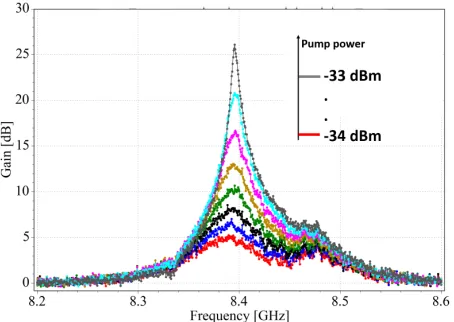
Figure 4.Gain obtained for different pump powers for a resonance frequency fR≈8.4 GHz. Different colors correspond to different input pump powers at the sample. The input signal power at the sample isPs=−20 dBm. The pump frequency isfp=2fR+δ, withδ=10 MHz
.
maximum gainG=25 dB and we obtain a−3 dB bandwidthBW =15 MHz forG=21 dB, which verifies our design target.
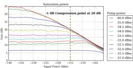
The characterization of the saturation power is shown in figure 5. We obtain a 1 dB compression point, defined as the input signal power at which the gain decreases of 1 dB, of P1dB = −115 dBm forG = 20 dB. This result is comparable with the state of the art of flux-pumped JPAs using arrays of SQUIDs [10]. The results of the characterization measurements are very promising for the future use of the developed amplifier as first stage of amplification for the readout of superconducting qubits [23].
4 Conclusions
Figure 5.Saturation power characterization. Gain as a function of the input signal power at the sample. Different colors correspond to different input pump power at the sample. The dashed line indicates the value of the 1 dB compression pointP1dB=−115dBm for a gain of 20 dB.
which are comparable with the state of the art of flux-pumped JPAs [10]. The estimation of the amplifier noise is subject of ongoing investigations. Overall, the performance of the amplifier are promising for our next goal which consists in using the developed amplifier as the first amplification stage for the single-shot readout of a coaxial transmon qubit, recently developed in our lab [23].
References
[1] R.J. Schoelkopf, S.M. Girvin, Nature451, 664 EP (2008)
[2] M.H. Devoret, R.J. Schoelkopf, Science 339, 1169 (2013), http://science.sciencemag.org/content/339/6124/1169.full.pdf [3] U. Vool, M. Devoret, International Journal of Circuit Theory and Applications45, 897
(2017),https://onlinelibrary.wiley.com/doi/pdf/10.1002/cta.2359 [4] M.A. Castellanos-Beltran, K.W. Lehnert, Applied Physics Letters91, 083509 (2007),
https://doi.org/10.1063/1.2773988
[5] V.E. Manucharyan, E. Boaknin, M. Metcalfe, R. Vijay, I. Siddiqi, M. Devoret, Phys. Rev. B76, 014524 (2007)
[6] T. Yamamoto, K. Inomata, M. Watanabe, K. Matsuba, T. Miyazaki, W.D. Oliver, Y. Nakamura, J.S. Tsai, Applied Physics Letters 93, 042510 (2008), https://doi.org/10.1063/1.2964182
[7] L. Zhong, E.P. Menzel, R.D. Candia, P. Eder, M. Ihmig, A. Baust, M. Haeberlein, E. Hoffmann, K. Inomata, T. Yamamoto et al., New Journal of Physics 15, 125013 (2013)
[8] J.Y. Mutus, T.C. White, R. Barends, Y. Chen, Z. Chen, B. Chiaro, A. Dunsworth, E. Jeffrey, J. Kelly, A. Megrant et al., Applied Physics Letters 104, 263513 (2014), https://doi.org/10.1063/1.4886408
[9] C. Eichler, A. Wallraff, EPJ Quantum Technology1, 2 (2014)
[10] X. Zhou, V. Schmitt, P. Bertet, D. Vion, W. Wustmann, V. Shumeiko, D. Esteve, Phys. Rev. B89, 214517 (2014)
[12] M.A. Castellanos-Beltran, K.D. Irwin, G.C. Hilton, L.R. Vale, K.W. Lehnert, Nature Physics4, 929 EP (2008)
[13] B. Ho Eom, P.K. Day, H.G. LeDuc, J. Zmuidzinas, Nature Physics8, 623 EP (2012) [14] C. Macklin, K. O’Brien, D. Hover, M.E. Schwartz, V. Bolkhovsky,
X. Zhang, W.D. Oliver, I. Siddiqi, Science 350, 307 (2015), http://science.sciencemag.org/content/350/6258/307.full.pdf
[15] F. Mallet, F.R. Ong, A. Palacios-Laloy, F. Nguyen, P. Bertet, D. Vion, D. Esteve, Nature Physics5, 791 EP (2009)
[16] E. Boyd,Non linear Optics (3rd ed.)(Academic Press, 2008)
[17] G. Cerullo, S. De Silvestri, Review of Scientific Instruments 74, 1 (2003), https://doi.org/10.1063/1.1523642
[18] K. O’Brien, C. Macklin, I. Siddiqi, X. Zhang, Phys. Rev. Lett.113, 157001 (2014) [19] T. Roy, S. Kundu, M. Chand, A.M. Vadiraj, A. Ranadive, N. Nehra, M.P. Patankar,
J. Aumentado, A.A. Clerk, R. Vijay, Applied Physics Letters 107, 262601 (2015), https://doi.org/10.1063/1.4939148
[20] S. Boutin, D.M. Toyli, A.V. Venkatramani, A.W. Eddins, I. Siddiqi, A. Blais, Phys. Rev. Applied8, 054030 (2017)
[21] M. Hatridge, R. Vijay, D.H. Slichter, J. Clarke, I. Siddiqi, Phys. Rev. B83, 134501 (2011)
[22] L. Planat, R. Dassonneville, J.P. Martinez, F. Foroughi, O. Buisson, W. Hasch-Guichard, C. Naud, R. Vijay, K. Murch, N. Roch,Understanding the saturation power of joseph-son parametric amplifiers made from squids arrays(2018),arXiv:1809.08476 [23] J. Rahamim, T. Behrle, M.J. Peterer, A. Patterson, P.A. Spring, T. Tsunoda,
R. Manenti, G. Tancredi, P.J. Leek, Applied Physics Letters 110, 222602 (2017), https://doi.org/10.1063/1.4984299
[24] A. Barone, G. Patero,Physics and applications of the Josephson Effect(Wiley, 1982) [25] S. Pogorzalek, K.G. Fedorov, L. Zhong, J. Goetz, F. Wulschner, M. Fischer, P. Eder,