1880 | P a g e
MOS CURRENT MODE LOGIC BASED PRIORITY
ENCODERS
Neeta Pandey
1, Kirti Gupta
2, Stuti Gupta
1, Suman Kumari
11
Dept. of Electronics and Communication, Delhi Technological
University, New Delhi (India)
2
Dept. of Electronics and Communication, Bharati
Vidyapeeth’s College of Engineering, New Delhi (India)
ABSTRACT
This paper proposes efficient circuit realizationsfor priority encoders in MOS Current Mode logic (MCML) style. The MCML based realization of look ahead priority encoder and ripple carry priority encoder are presented. Two different realization for a particular priority encoder are given based on the series-gating approach and the fundamental cell based approach. The proposed circuits are simulated in PSPICE using 180 nm CMOS technology parameters. It is found that the proposed circuits exhibits the correct functionality. Also, the performance of the proposed circuits is compared in terms of power, propagation delay and power delay product. The performance comparison with the CMOS counterparts has also been included. It is found that the fundamental cell based priority encoders outperforms with reference to the series gating MCML based and the static CMOS based encoders.
Keywords
:
digital circuits, mixed-signal design, PFSCL, Fundamental cell, priority encoder
I. INTRODUCTION
MOS Current Mode Logic (MCML) circuits has enabled the design of circuits suited to the new digital
information age. The style possesses features like frequency independent power consumption, low switching
noise which makes it appropriate to design digital circuits for mixed-signal applications in comparison to CMOS
logic style [1-4]. Their application areas include microprocessor design, mobile communication and optical
transmission links etc.In microprocessors they are employed in the design of datapath as well as the control path
of the processor. A large variety of arithmetic circuits such as adder, multiplier, decoder, flip flops, shift
registers etc have been implemented in the logic style [5-8].
This paper focusses on the implementation of priority encoders in MCML logic style. The traditional MCML
topology is based on the series-gating approach consisting of stacked source-coupled transistor pairs. This
arrangement puts a limit on the minimum supply voltage value. A technique wherein the minimum power
supply value is reduced in comparison to the traditional approach has been suggested in literature. This
1881 | P a g e
paper, MCML implementation of the priority encoders based on the traditional series-gating approach and the
fundamental cell is proposed.
In this paper, the basics and working of priority encoders are briefly reviewed in section 2. Then the concept of
MCML technique are briefly discussed in section 3. Thereafter section 4 presents the simulation results for the
proposed MCML priority encoders. The simulations are performed in PSPICE using 180 nm CMOS technology
parameters. The last section 5 concludes the paper
II. PRIORITY ENCODERS
A priority encoder is a combinational circuit wherein the output is produced according to the priorities assigned
to the input lines [9]. Therefore, when an input with a higher priority is present, all other inputs with a lower
priority will be ignored.Priority encoders are extensively employed in number of decision making components
used in computer systems and other sub-systems. Thus, in situations wherein several processes, modules, or
units request a single hardware (or software) resource in the system, a decision is made to allow a single request
to use such a resource by the encoder. It is generally employed to implement a prioritized selection function in
which the resource is granted to the request with the highest priority according to the selection function
specified or coded. Some of the application includeenergy-efficient adaptive hybrid cache,a leakage energy
reduction addressable memory design,bank structure in complex memories
To illustrate the working mechanism of a priority encoder, it is assumed that it is a circuit which is used to
arbitrate among N units requesting to access a shared resource [20]. Each unit irequest by sendinga bit Ai and receives a bit Yi in response which indicates whetehr the access has been gratnted or not. It is obvious that the access will be granted to a single unit with highest priority. If the least significant bit of the input corresponds to
the highest priority, the logic for a priority encoder with 4 input lines can be expressed as follows:
Y1 = A1 (1)
Y2= A2 *(~A1) (2)
Y3= A3 *(~A2)*(~A1) (3)
YN= AN *(~AN-1)*……*(~A1) (4)
There different types of priority encoders available in literature which are rated on the basis of speed and power.
Some of the available priority encoders are look ahead priority encoder, ripple priority encoder, increment
priority encoder, Sklansky priority encoder
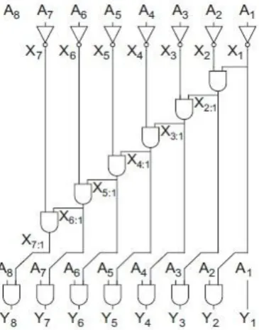
2.1 Look Ahead Priority Encoder
The purpose to design a look ahead priority encoder is to minimize the propagation delay of the priority status
during the worst case operation, hence increasing the speed of the circuit. A multilevel look- ahead structure
1882 | P a g e
Fig. 2: Look ahead Schematic Diagram
2.2 Ripple Priority Encoder
They are widely used when meeting timing constraints because they use the least energy and have the simplest
design in which the logic-out of one bit is simply connected as the logic-in to the next.
1883 | P a g e
III. MOS CURRENT MODE LOGIC (MCML) STYLE
MCML style is a differential style that operates on the principle of current steering. The basic architecture of a
MCML gate consist of a pull down network(PDN), load resistance and a constant current source. The logic
function is realized in the PDN based on the series gating approach. The schematic of a CML inverter with
inputs (vin1 and vin2) and outputs (vout1 and vout2) is shown in Fig. 3. The PDN comprises of source coupled
transistor pair (M2-M3), the current source use an NMOS transistor M1 operating in saturation region whereas
the passive resistors R1, R2 act as load for the inverter circuit. The bias current ISS is completely steered to one
of the two output branches depending on the differential input voltage. The current steered in the inverter is
converted into the differential output voltage (vout = vout1 - vout2), through the passive resistors R1 and R2.
The series-gating approach is used to realize MCML gates [27]. It is a systematic and a general approach
wherein an arbitrary logic function F(Y1,….Yn) is implemented as an network of source-coupled transistor
pairs having all transistor paths associated with the 2n possible input combinations and then properly connecting
each of the upper drain nodes to the output nodes. This is illustrated in Fig. 4. Based on this concept, it is
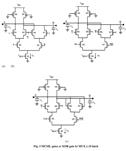
possible to realize basic combinational gates such as exclusive-OR (XOR) gate, 2:1 multiplexer (MUX) etc. and
sequential circuits such as D latch. The corresponding realizations are depicted in Fig. 5.
Fig. 4 A generalized two level MCML gate
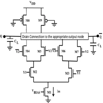
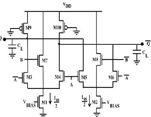
Another approach named as fundamental cell based approach is used to realize combinational gates such as an
exclusive-OR (XOR) gate, 2:1 multiplexer (MUX). It consists of two triple-tail cells (M3, M4, M7) and (M5,
M6, M8) biased by separate current sources of ISS/2 value. The transistors M7 and M8 are driven by the
differential input B and are connected between the power supply terminal and the common source terminal of
transistor pairs (M3 – M4) and (M5– M6) respectively. A XOR gate with differential inputs A and B (Fig. 6) is
examined.A high voltage on differential input B turns ON the transistor M7, and deactivates the transistor pair
1884 | P a g e
output according to the differential input A. Similarly, the transistor pair (M3 - M4) gets activated for lowdifferential B voltage and produces the corresponding output.
(a) (b)
(c)
1885 | P a g e
Fig. 6 Fundamental cell based two input XOR gateThe traditional unbalanced and series-gate approach followed to implement MCML gates does not lead to
significant power reduction. However, alternative approaches can be exploited to build MCML gates with are
reduced supply voltage. This is because in the series- gate approach, Vdd must be sufficiently high to ensure
that all transistors work out of the saturation region, according to number of stacked levels .One technique that
allows for a Vdd reduction with respect to traditional MCML gates is the triple-tail approach that appears to be
the most promising of all since it operates with the lowest supply voltage. Therefore, in the following analysis
only triple-tail approach will be considered and accordingly it will be referred to as the low-voltage topology.
IV. SIMULATION RESULTS
The look ahead and ripple carry priority encoder circuits shown in Fig, 1 and Fig. 2 are implemented in MCML
style using traditional; series gating approach as well as fundamental cell based approach. All the simulations
are performed in PSPICE using 180-nm CMOS technology [10]. For allthesimulations, someconditions common
to all design are thelengthof MOS transistorsis constant and is equal to 0.18μm.Thevoltage swing, Vswingis
constant, Vswing=400mV. Theconstant current of 100 μA is maintained in all the MCML gates.
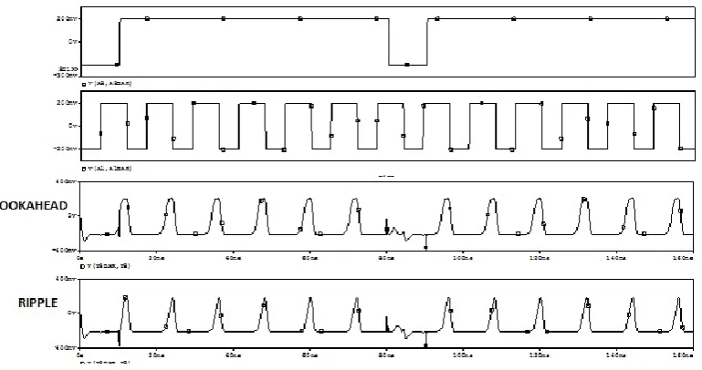
The functionality of the proposed MCML priority encoder is verified through simulation. The simulation graph
for encoders based on series gating approach are shown in Fig. 7. It can be seen that both the encoders are
exhibitingthe correct functionality. The simulations for the encoders based on fundamental cellare also
performed. Similar waveforms were observed which are not shown for the sake of the brevity. properly. The
performance of the proposed encodersis measured in terms of the propagation delay, power consumption and
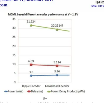
power delay product (PDP). For the purpose of fair comparison, the simulation results for the CMOS based
encoders have also been included. A performance comparison between the CMOS and MCML based encoders
is shown in Fig 8. The results clearly indicates that the MCML based encoders outperforms the CMOS based
1886 | P a g e
fundamental cell based approach is also done. The results are summarized in Table I.It is found that thefundamental cell based priority encoder shows lower values pertaining to the delay and power. Thus, it is clear
that the encoder realizations based on the fundamental cell based approach will results in efficient encoder
design.
Fig. 7 Simulation waveform for the proposed MCML priority encoders based on the series gating
approach
1887 | P a g e
(b)Fig. 8 Performance comparison of CMOS and MCML based priority encoder
Table. I:Powerconsumptionfor differentencoders at differentvoltagesupply.
Encoder V=1.8V V=1.4V V=1.1V
Power
Lookahead 3.96mW 3.08mW 2.42mW
Ripple 3.6 mW 2.8 mW 2.2 mW
Delay
Lookahead 2.95 ns 5.157 ns 5.114 ns
Ripple 3.09 ns 6.15 ns 6.09 ns
V. CONCLUSION
In this paper MCML based realization of priority encoders in MOS Current Mode logic (MCML) style are
proposed. The two types of encoders named as look ahead priority encoder and ripple carry priority encoder are
presented. The MCML circuits based on the series-gating approach and the fundamental cell based approach are
realized. The functionality of the proposed circuits is verified through simulation in PSPICE using 180 nm
CMOS technology parameters. It is found that the proposed circuits exhibits the correct functionality. Also, their
performance is compared in terms of power, propagation delay and power delay product. The results for the
CMOS counterparts has also been included. It is found that the fundamental cell based priority encoders shows
the lowest value in all the considered performance parameters. Hence, fundamental cell based priority encoders
1888 | P a g e
REFERENCES
[1] Musicer J. M., Rabaey, J. MOS Current Mode Logic for Low Power, Low Noise, CORDIC Computation in
Mixed-Signal Environments. In Proc. International Symposium of Low Power Electronics and Design,
2000, 102-107.
[2] Hassan, H., Anis, M., Elmasry, M. MOS Current Mode Circuits: Analysis, Design, and Variability. IEEE
Transactions on Very Large Scale Integration (VLSI) Systems, 13(8),2005, 885 - 898.
[3] Nonis, R., Palumbo, E., Palestri, P., and Selmi, L. A Design Methodology for MOS Current-Mode Logic
Frequency Dividers, IEEE Transactions on Circuits and Systems– II: Regular Papers, 54(2), 2007, 245-254.
[4] Alioto, M., Palumbo, G. Model and Design of Bipolar and MOS Current-Mode logic (CML, ECL and SCL
Digital Circuits), Springer, 2005.
[5] Caruso, G. Power-aware design of MCML logarithmic adders. Proc. International Conference on Signals
and Electronic Systems, 2010, 281-283.
[6] Yassmeen, M., El-Hariry, Madian, A. H. MOS Current Mode Logic Realization of Digital Arithmetic
circuits. Proc. IEEE International Conference on Microelectronics, 2010, 1-4.
[7] Worapishet, A., Thamsirinumt, M. An NMOS Inductive Loading Technique for Extended Operating
Frequency CMOS Ring Oscillators, Proc. Mid-west Symposium on Circuits and Systems, 2002, 116-119.
[8] Gupta, K., Pandey, N, Gupta, M. Shunt-Peaking in MCML Memory Element Design in 0.18μm CMOS
Technology. Proc. IEEE INDICON, Kolkata (India),2010, 1-4.
[9] Razavi, B. Design of Analog CMOS Integrated Circuits, Mc-Graw Hill Higher Education, 2001
[10] K. Gupta, N. Pandey, and M. Gupta, “Analysis and Design of MOS Current Mode Logic Exclusive-OR
Gate using Triple-tail Cells,” Microelectronics Journal, vol. 44, no. 6, pp. 561-567, 2013.
[11] K. Gupta, N. Pandey, and M. Gupta, “MCML D-Latch Using Triple-Tail Cells: Analysis and Design,”
Active and Passive Electronic Component, vol. 2013, pp. 1-9, 2013.
[12] N. Pandey, K. Gupta, and M. Gupta, “An Efficient Triple-tail Cell based PFSCL D Latch,”