ISSN(Online): 2320-9801 ISSN (Print) : 2320-9798
I
nternational
J
ournal of
I
nnovative
R
esearch in
C
omputer
and
C
ommunication
E
ngineering
(An ISO 3297: 2007 Certified Organization)
Vol. 4, Issue 2, February 2016
Comparative Study on Interrogation
Techniques of Fiber Bragg Grating Sensor
Array
Vini Susan Ninan1, Jaini Sara Babu2
PG Student [OEC], Dept. of ECE, TKM Institute of Technology, Kollam, Kerala, India1
Assistant Professor, Dept. of ECE, TKM Institute of Technology, Kollam, Kerala, India2
ABSTRACT: Fiber optic technology has seen tremendous growth both in the field of telecommunications and sensing.
FBG sensors are suitable for sensing and data acquisition, where sensors can be multiplexed using various interrogation techniques like Wavelength Division Multiplexing (WDM), Time Division Multiplexing (TDM),Optical Code Division Multiplexing (OCDM), Polarization division multiplexing (PDM) etc. Polarization Division Multiplexing (PDM) as a method of interrogation is preferred. This technique uses a polarizer with known predetermined angle of polarization for each sensor. The reflected lights from different sensors are aligned at unique angles of polarization with reduced cross talk and interference. Thus unique identification of each sensor data can be obtained by using this technique. If sensors at different location have same data, sensor also can be properly identified. The main advantage of this technique is small size even if large number of sensors is interrogated in an array, separated by small angles.
KEYWORDS: Fiber Bragg Grating, Optical Code Division Multiplexing, Optical Time Division Multiplexing,
Polarization Division Multiplexing, Wavelength Division Multiplexing.
I. INTRODUCTION
Earlier, electrical sensors have been used as the standard mechanism for measuring mechanical and physical phenomena. The inherent limitations of these sensors are highly immune to electromagnetic interference and transmission loss that make their usage impractical in many applications. An excellent solution to overcome these challenge is fiber-optic sensing which uses light rather than electricity and optical fiber instead of copper wire. Over the last two decades fiber-optic communication industries has improved the quality and significantly reduced optical component prices.
ISSN(Online): 2320-9801 ISSN (Print) : 2320-9798
I
nternational
J
ournal of
I
nnovative
R
esearch in
C
omputer
and
C
ommunication
E
ngineering
(An ISO 3297: 2007 Certified Organization)
Vol. 4, Issue 2, February 2016
II. FIBER BRAGG GRATINGS
Gratings are simple, intrinsic sensing elements with inherent self referencing capability. this can be photo-inscribed into the core of an optical fiber by using different techniques such as Interferometric method, phase-mask technique etc.. These devices can be easily multiplexed along a single fiber .Gratings can be used as the sensing element in fiber sensor configurations such as pressure sensors, grating-based chemical sensors, accelerometers are examples.
A fiber Bragg grating is a wavelength dependent reflector or filter formed by introducing a periodic refractive index variation within the core of an optical fiber. According to Bragg’s law, light from a broadband source is passed through an optical fiber inscribed with fiber bragg grating, which will reflect a narrow portion of the light at specific wavelength, which is called as the Bragg’s wavelength. The Bragg’s wavelength depends on the refractive index of the fiber and period of the grating. The Bragg’s wavelength equation is
λB= 2neΛ (1)
where neis the effective refractive index of the fiber, Λ is the period of grating.[2]
III. RELATED WORKS
Mahdiraji [3] proposed recent research advances on the design and fabrication of new FBG sensors. Optical fiber gratings are still playing a significant role for developing a wide variety of sensors with the fusion of new fiber materials and structures. Those new kinds of FBG sensors hold great potential for various industrial applications.
Majid [5] introduced a method in which WDM multiplexer/demultiplexer was designed using the Bragg wavelengths of every FBG. In this design, UFBG was experimentally implemented. By properly choosing the Bragg wavelengths of the UFBG. There was a problem that faced this design, which is grating dispersion that affects the performance of a WDM network incorporating cascaded gratings. Two UFBG filter were used,where the transmitted channel may be distorted due to dispersion. This problem was solved by using ideal compensator to compensate dispersion. Finally, the results of this work may be also important in designing of recently proposed multiple-grating fiber structures for WDM multiplexer and demultiplexer
Saikat Saha [6] proposed a new system in which optical CDM system has been designed using spectral encoding and decoding schemes. This technique helps to overcome Multiple Access Interference and moreover it is bandwidth efficient. Fiber Bragg grating is used for encoding and decoding. Performance of the OCDMA system decreases as the bit rate increases. This is due to effect of attenuation and dispersion in the fiber.
IV. SYSTEM MODELLING
Whenever the bandwidth needs of the devices are greater than the bandwidth of the medium linking two devices, that link can be shared. A technique that allows the transmission of multiple signals simultaneously across a single channel is called multiplexing. Higher bandwidth links can be installed and use each to carry multiple signals. Recent technology includes higher bandwidth media such as terrestrial, satellite and optical fiber. These all has an excess bandwidth that needed for the average transmission of a signal. If the bandwidth of link is greater than the bandwidth needs of the devices, bandwidth is wasted [3].
The basic multiplexing techniques are time division multiplexing (TDM), wavelength division multiplexing (WDM), and optical code division multiplexing (OCDM). To avoid the drawbacks of these multiplexing techniques, another multiplexing technique called Polarization Division Multiplexing (PDM) is used.
3.1 Optical Time Division Multiplexing
ISSN(Online): 2320-9801 ISSN (Print) : 2320-9798
I
nternational
J
ournal of
I
nnovative
R
esearch in
C
omputer
and
C
ommunication
E
ngineering
(An ISO 3297: 2007 Certified Organization)
Vol. 4, Issue 2, February 2016
output channels. The receiver should identify each bit correctly, so proper synchronization is needed for this operation. That is signals should be uniquely synchronized in time with beginning of each frame, for that over head bits are added.[3] [4]
Fig 1: Simulation model of Optical Time Division Multiplexing
3.2 Wavelength Division Multiplexing
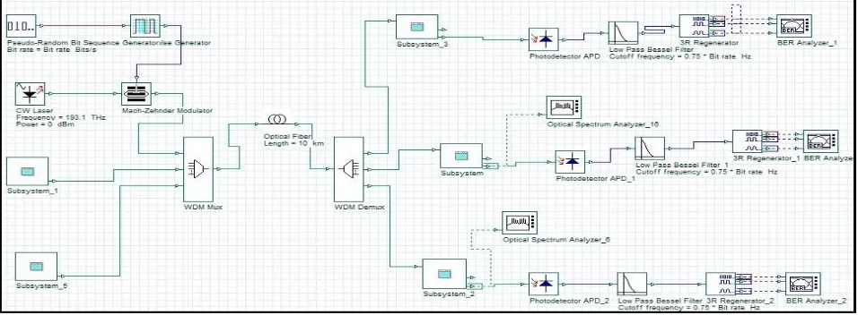
Wavelength Division Multiplexing (WDM ) is a process where different independent users transmit data over a single link using different wavelength. ‘N’ independent user date with unique wavelength is modulated into ‘N’ high frequencies. The multiplexer combines these signals and the multiplexed optical signals are coupled into the optical fiber. At receiving end, a demultiplexer is used to separate these optical signals. Channel spacing will determine the total capacity of the system. The major disadvantage of the system is low spectral efficiency and channel utilization because one wavelength is required per user. The use of filters, amplifiers will increase the cost of the system.[5]
Fig 2: Simulation model of Wavelength Division Multiplexing
ISSN(Online): 2320-9801 ISSN (Print) : 2320-9798
I
nternational
J
ournal of
I
nnovative
R
esearch in
C
omputer
and
C
ommunication
E
ngineering
(An ISO 3297: 2007 Certified Organization)
Vol. 4, Issue 2, February 2016
Fig 3: Sub system simulation for dispersion compensation
3.3 Optical Code Division Multiplexing (OCDM)
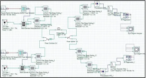
Optical Code Division Multiplexing (OCDM ) offers enhanced information security. The network based on code has the potential to simplify network control and management. This allows multiple users to access the channel asynchronously and simultaneously without any delay. It is noise limited due to the multiple access interference (MAI ) from different user codes. MAI results in overlapping and corrupting of encoded signals, thus introduce bit error rates which will degrade the system performance. Fiber Bragg Grating (FBG) at the transmitting and receiving end is used to encode and decode the signal. As the bit rate increases, performance of the system gets degraded.[6]
ISSN(Online): 2320-9801 ISSN (Print) : 2320-9798
I
nternational
J
ournal of
I
nnovative
R
esearch in
C
omputer
and
C
ommunication
E
ngineering
(An ISO 3297: 2007 Certified Organization)
Vol. 4, Issue 2, February 2016
3.4Polarization Division Multiplexing ( PDM)
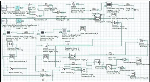
Polarization division multiplexing (PDM) is a technique where two independently modulated data channels with the same wavelength, but orthogonal polarization states are simultaneously transmitted in a single fiber link which will double the capacity of the system or spectral efficiency. At receiving end, these signals are detected independently. This can reduce the interference and cross talk in FBG sensor array.PDM can be implemented in high speed optical networks. Polarizer’s with predetermined angles at the output of each FBG sensor will reduce the cross talk and interference issues. Polarization rotator and polarization attenuator can separate the reflected light from each sensor.[3]
A broadband optical source is used as a transmitter which has been generated using the nonlinear phenomenon of cross phase modulation (XPM). Two continuous waves with different wavelengths will co-propagate in the optical fiber and act as a broadband optical source. The desired frequency band is filtered out using a Gaussian band pass filter
.
The reflected light from FBG is fed to polarization rotator with predetermined angle. The signal from polarization rotators are combined using a polarization combiner and output of the polarization combiner is combined with signal from polarization rotator 1 by the use of a power combiner. Each polarization rotator is set with a predetermined angle there by interference of signals from adjacent sensors can be avoided. By using a polarization splitter the signals get splitted and fed to the receiver. The receiver stage consists of eye diagram analyser gives the value of maximum Q factor, minimum BER, eye height.[1]Fig 5: Simulation model of Polarization Division Multiplexing
V. RESULT AND DISCUSSION
ISSN(Online): 2320-9801 ISSN (Print) : 2320-9798
I
nternational
J
ournal of
I
nnovative
R
esearch in
C
omputer
and
C
ommunication
E
ngineering
(An ISO 3297: 2007 Certified Organization)
Vol. 4, Issue 2, February 2016
Table 4.1 Optical Time Division Multiplexing:
LENGTH (km) Q-FACTOR
10 10.024
20 7.238
30 5.587
From Table 4.1 it is clear that Optical Time Division Multiplexing has maximum transmission capacity upto 30km.
Table 4.2 Wavelength Division Multiplexing:
LENGTH(km) Q-FACTOR
10 240.546
70 89.9819
140 12.35
Transmission capacity of Wavelength Division Multiplexing at different fiber lengths is given i n Table 4.2. WDM system has maximum transmission capacity upto 140km.
Table 4.3 Optical Code Division Multiplexing:
LENGTH(km) Q-FACTOR
10 20.58
60 10.0952
120 7.2146
Optical Code Division Multiplexing at different fiber lengths is given in the Table 4.3 . The transmission capacity of OCDM is limited upto 120km.
Table 4.4 Polarization Division Multiplexing:
LENGTH(km) Q-FACTOR
10 442.223
90 79.0801
180 5.59834
Table 4.4 shows the performance analysis of Polarization Division Multiplexing at different fiber lengths. PDM has the maximum transmission capacity upto 180km. Polarizer’s at end of each sensor will reduce the interference there by allowing long distance transmission.
VI. CONCLUSION
ISSN(Online): 2320-9801 ISSN (Print) : 2320-9798
I
nternational
J
ournal of
I
nnovative
R
esearch in
C
omputer
and
C
ommunication
E
ngineering
(An ISO 3297: 2007 Certified Organization)
Vol. 4, Issue 2, February 2016
offers high resolution and accuracy , but cost of this system is high and it offers relatively low sampling rates. OCDM uses unique code with enhanced security. Performance of the system decreases as the bit rate increases. To overcome the drawbacks of OTDM, WDM and OCDM, another multiplexing technique called PDM is used. PDM has the capability of rejecting interference and crosstalk from other sensors in the sensor array. In PDM large number of sensors can be interrogated in an array, without changing the optical fiber. Multiplexing techniques like OTDM, WDM and OCDM can increase its transmission capacity up to 30 km, 140 km and 120 km respectively. Compared with these multiplexing techniques, PDM has increased transmission capacity up to 180 km with reduced cost. The main advantage of this technique is its small size even if the number of sensors in an array is large as the sensors in an array are separated from each other by small angles.
REFERENCES
1. Debabrata Sikdar, Vinita Tiwari, Anupam Soni, Rithesh Jaiswal ,Surekha Bhanot, “Polarization Multiplexed Interrogation Technique For FBG Sensor Array”, Photonic Sensors,vol.5, no.3,2015:193201
2. A. D. Kersey, M. A. Davis, H. J. Patrick, M. Le Blanc, K. P.Koo, C.G.Askins, et al., ”Fiber grating sensors”’ Journal of Light wave Technology, 1997, 15(8) 14421463
3. Ghafour Amouzad Mahdiraji and Ahmad Fauzi Abas ,“Advanced ModulationFormats and Multiplexing Techniques for Optical Telecommunication Systems”,Trends in Telecommunications Technologies,2014
4. M.A. Othman, M.M. Ismail, H.A. Sulaiman, M.H. Misran, M.A. Meor Said,Y.A. Rahim, A.N. Che Pee, M.R. Motsidi, “An Analysis of 10 Gbits/s Optical Transmission System using Fiber Bragg Grating (FBG)”ISSN 2250-3021 Volume 2, Issue 7(July 2012)
5. Sawsan Abdul- Majid , Saleh Al Qaraawy, Yousra Abdul-sahib ”SoftwareSimulation of Fiber Bragg Grating In WDM”, IJCCCE, Vol.6,no.2,2006
6. Saikat Saha, Sugumaran. S, “Design and Study of Optical CDMA system”, International Journal of Research in Engineering and Advanced Technology, Volume 2, Issue 2, Apr May, 2014
7. Li Wei ,Zhang Yongjia1,b,Wen Hongqiao, “ Multiple Fiber Grating SensorSystem using Code Division Multiple Access” International Conference On Systems Engineering and Modeling 2013
8. Wei Li , “Fiber Bragg grating sensing system based on code division multiple access” Chinese Optics Letters COL 11(Suppl.), S20602(2013)
BIOGRAPHY
Ms. Vini Susan Ninan received her B Tech degree in Electronics and Communication Engineering from Mahatma Gandhi University in 2012. She is currently pursuing second year M Tech in Optoelectronics and Communication at TKM Institute of Technology.