Review
1
A Review of Research on Light Visual Perception of
2
Unmanned Surface Vehicles
3
Zhang wei1*, Wang Bo2
4
1 Harbin Institute of Technology; [email protected]
5
2 Harbin Engineering University; [email protected]
6
* Correspondence: [email protected]; Tel.: (086-18846937196.)
7
Abstract: Unmanned surface vehicles have the advantages of maneuverability, concealment, wide
8
activity area and low cost of use. Therefore, they have broad application prospects. This makes
9
unmanned surface vehicles a research hotspot at home and abroad, and the sensing technology is
10
the basis for the unmanned surface vehicles to perform tasks. The perception technology based on
11
optical vision has the advantages of convenient application, relatively low cost, easy data acquisition
12
and large amount of information, and has been widely studied by scholars at home and abroad.
13
This paper mainly discusses the research of optical vision in unmanned surface vehicles from five
14
aspects: Firstly, the water surface image preprocessing based on unmanned surface vehicles, mainly
15
including water surface image stabilization research and defogging enhancement research; two
16
water boundary detection; It is the use of light vision target detection; the fourth is the surface target
17
tracking method. Finally, the light vision research of unmanned surface vehicles is summarized and
18
forecasted.
19
Keywords: unmanned surface vehicles; optical visual perception; image stabilization; defogging; target
20
detection; target tracking
21
22
1. Introduction
23
An unmanned surface vehicles, referred to as an unmanned surface vessel, is an unmanned
24
surface ship. In 2007, the US Navy released the first Naval Unmanned surface vehicles Master Plan,
25
which defined the unmanned surface vehicles as a kind of floating surface when it was still, and
26
almost continuously contacted with the water during exercise, and Unmanned aerial vehicles with
27
different automatic control capabilities [1]. And the demand for this technical field in the document
28
is: "Further increase the regional coverage and improve the water surface. The ability to detect,
29
classify, and identify targets, as well as tracking techniques, to improve sensors for detecting chemical,
30
biological, nuclear, radiological, and explosion threats [2]. The unmanned surface vehicles has the
31
ability to perform some tasks independently or completely independently. Compared with other
32
conventional marine equipment, the unmanned surface vehicles have the characteristics of
33
maintenance cost, low energy consumption and long continuous operation time, which can meet the
34
realistic large surface area. Long-term research tasks and engineering project requirements. In
35
addition, unmanned surface vehicles can replace people with complex and dangerous work by
36
carrying different functional modules, such as disaster search and rescue, hydrological information
37
monitoring and collection, marine biological information collection, and regional Chart topographic
38
mapping, marine weather forecasting; adjacent sea defense missions; search, detection and demining
39
of specific waters, combating pirates, counter-terrorism missions, etc.
40
Unmanned surface vehicles encounter many problems that do not exist on land and in the air.
41
For example, it may encounter severe sea conditions such as heavy fog or heavy water vapor on the
42
surface when performing tasks. These severe working environments have a great impact on the
43
sensors carried by the unmanned surface vehicles and their own movements, and also put forward
44
high requirements for the environmental awareness of the unmanned surface vehicles [3]. According
45
to the scheduled tasks, the unmanned surface vehicles must be able to sail smoothly in various
46
unknown marine environments, perform environmental detection, surface target detection, target
47
recognition, autonomous obstacle avoidance, and autonomous tasks. The realization of these
48
capabilities is supported by the environmental awareness technology of unmanned surface vehicles.
49
For the environmental sensing technology of unmanned surface vehicles, it mainly includes
50
sensing technologies such as light vision, radar, infrared and underwater sound. Compared with
51
other sensing technologies, optical images contain more detailed information on the target area, and
52
the data is easy to obtain and the amount of information is large[2]. At the same time, light
vision-53
based sensing technology makes it easier to effectively identify surface targets. Light vision is the
54
perception technology that is closest to humans to obtain information. Humans obtain more than 80%
55
of information through vision. The optical visual perception technology is beneficial to the effective
56
extraction of navigational vessels, surface floating obstacles, artificial water facilities, island
57
topography and other information during the operation of the unmanned watercraft, which helps
58
them to complete independent planning and self-collision avoidance. The realization of tasks such as
59
environmental monitoring, so as to avoid the collision of the unmanned surface vehicles and the
60
surface target, on the other hand, it can ensure the accuracy of the information of the monitoring
61
target, and improve the intelligent level of the unmanned surface vehicles.[4] .
62
This paper mainly discusses the research of unmanned light visual perception technology from
63
five aspects: one is the water surface image preprocessing based on the unmanned surface vehicles;
64
the second is the sea boundary line detection method; the third is the water surface moving target
65
detection method; the fourth is the water surface motion Target tracking method.
66
2. Water surface image preprocessing based on surface unmanned vehicles
67
The purpose of water surface image preprocessing is to obtain a clear and stable image sequence
68
by processing the original image. The stable and clear image sequence can greatly improve the ability
69
of unmanned light sight avoidance, detection, tracking and recognition. Unmanned surface vehicles
70
are affected by irregular wind and waves during the navigation process, resulting in irregular
71
swaying of the hull posture, causing shaking, vibration and distortion of the images taken by the
72
mounted camera [5], resulting in video images captured by the visual system. Severe degradation,
73
affecting the performance of the unmanned visual system, will have a great impact on the ability of
74
the unmanned surface vehicles to detect, track and identify. Therefore, research on the stabilization
75
technique of various sports has a strong practical significance [6]. At the same time, clear scene
76
information is also one of the powerful guarantees for realizing the function of the unmanned visual
77
system. However, sea fog often occurs at sea, and the visibility and contrast of the scene captured by
78
the camera are greatly reduced. The sea fog reduces the visibility of the atmosphere, the image of the
79
optical device is blurred, the resolution is reduced, and the clear image surface feature information
80
cannot be obtained, which seriously affects the extraction of the image information, which brings
81
great difficulty to the image information extraction. Therefore, effectively eliminating the influence
82
of sea fog is a necessary way to improve the availability of image data of unmanned surface vehicles.
83
2.1 Stabilization method for irregular shaking of unmanned surface vehicles
84
The unmanned surface vehicles are affected by the working environment, and there are wave
85
interference and self-vibration. The working effect of the sensing system is affected by the attitude
86
change or vibration of the carrier at different moments, and the obtained image information is
87
unstable and fuzzy. Such unstable images can cause fatigue to the observer, which leads to
88
misjudgment and missed judgment; for the target automatic identification system, the detection
89
target position is larger, errors, false alarms and false alarms. Therefore, in the unmanned surface
90
vehicles carrier, the image stabilization of the camera system is a very important problem, especially
91
in the long-focus, high-resolution unmanned surface vehicles monitoring and tracking system. There
92
are three commonly used image stabilization methods, namely active image stabilization, passive
93
image stabilization and electronic image stabilization. Active stabilization is a stable camera system
with a gyro-stabilized platform. The gyro-stabilized platform mainly attenuates low-frequency
95
vibration. Passive stabilization uses a vibration damping device to isolate the vibration of the carrier
96
and suppress the effects of high frequency vibration on the camera. Active image stabilization and
97
passive image stabilization can be used together to achieve a wide range of image stabilization.
98
However, the high-precision gyro-stabilized platform is not only complicated in structure, large in
99
size, expensive, and consumes a large amount of power, but also cannot be used due to volume
100
limitations on an unmanned surface vehicle platform. Therefore, the most widely used is electronic
101
image stabilization technology to achieve the stability of television images [7,8].
102
According to the imaging characteristics in the sea environment, based on the inter-frame
103
compensation method, the National University of Defense Technology designed an electronic image
104
stabilization algorithm based on the characteristics of water antennas [9]. The algorithm first extracts
105
the features of the water antenna, and then uses the linear parameters of the water antenna to
106
calculate the motion deviation between the image and the reference image, and then obtains the
107
interframe compensation. Finally, the image motion is stabilized by the image shift compensation
108
technique. According to the sea environment and lighting conditions, the experimental data is
109
divided into three categories, the average time for processing each typical sea-sky image is 39ms, the
110
image affected by the weather is 41ms, and the time of the sea-sky image with obstacles is 52ms,
111
which meets the requirements of 60ms in engineering. And the image output by the algorithm can
112
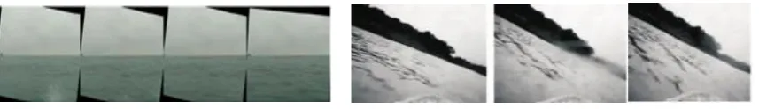
stabilize the water antenna within one pixel. Figure 1 is an effect diagram of an electronic image
113
stabilization algorithm based on the characteristics of a water antenna. On this basis, Beijing Institute
114
of Technology uses feature points extracted from successive frames to estimate motion parameters
115
for image stabilization. Motion compensation is achieved by converting the current frame to a
116
reference frame, the reference of which depends on the different compensation methods. The
117
experimental results show that the stability rate reaches 25 frames per second with a tracking window
118
size of 1×12×128 pixels.
119
For the video image jitter problem of high-speed unmanned surface vehicles in the process of
120
video acquisition, Harbin Engineering University uses the scale-invariant feature transform
121
algorithm to extract feature points in video images [10] using affine models to solve motion
122
parameters, and using Kalman filter to video The normal scanning in the image is filtered, and finally
123
the image compensation is performed by the adjacent frame compensation method to realize the
124
image stabilization processing of the high-speed unmanned surface vehicles. The algorithm uses the
125
video collected by the high-speed surface remote control boat for comparison verification analysis.
126
The results show that the algorithm is effective for the image stabilization of the high-speed
127
unmanned surface vehicles vision system, and can obtain a stable image sequence. Figure 2
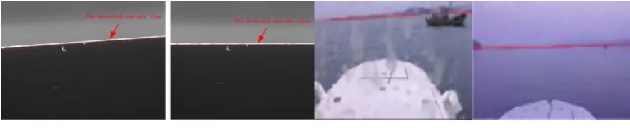
two-128
frame image and its processing effect. However, the algorithm has a poor effect on the large-scale
129
translational motion, and the calculation amount is large, and the real-time performance needs to be
130
improved. Later, according to the various displacement parameters of the obtained image,
131
corresponding compensation is performed to realize electronic image stabilization processing. Firstly,
132
the Kalman filter is used to filter the image. This process removes the normal scan contained in the
133
image, and finally obtains the displacement parameter corresponding to the jitter in the image, and
134
then compensates the image according to the adjacent frame compensation, and finally realizes the
135
electronic image stabilization processing.
136
Figure 1. Generalized water antenna electronic
image stabilization effect Figure 2. two images and their processing renderings Han Liangliang of Harbin Engineering University is aiming at the possible rotation and scaling
137
jitter in the process of obtaining the target image, and extracting and matching the SIFT feature points
138
in the scale space, and further screening by using the Rasanc algorithm to obtain the affine
transformation model of the interframe motion[11]. Image compensation based on bilinear
140
interpolation algorithm. The experimental results show that the proposed algorithm achieves better
141
image stabilization for the obtained maritime target video.
142
Figure 3. Eliminate SIFT feature point pairs obtained by pairing after mismatch
The University of Maryland has focused on military image stabilization technology and has
143
successfully developed a variety of image stabilization algorithms that have been successfully
144
applied to weapons and equipment. The University of Maryland has developed a digital image
145
stabilization system that can process image sequences with large deformations. The system has been
146
implemented in parallel processing image processing hardware (Datacube Max Video 200) connected
147
to SPARCstation 20/61 [12]. The processing algorithm tracks a set of image sequences based on
multi-148
resolution motion estimation of the two-dimensional features, which in turn estimates the motion
149
form and pose of the camera. Stabilization is achieved by using a combined estimate of the reference
150
frames to correct the current frame. The experimental conditions of the algorithm are similar to those
151
of the unmanned surface vehicles shaking on the water surface, and can be used as a reference for
152
the image stabilization of the unmanned light vision system. Using a video sequence of an unmanned
153
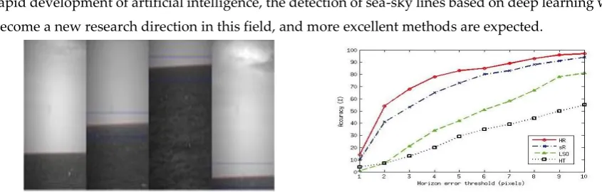
camera-mounted camera running on a rugged road, the algorithm has a processing capacity of 15
154
frames/s and can process successive frames of up to 21 pixels between frames. However, sometimes
155
the sequence acquired under shaking conditions cannot be processed stably, and the robustness of
156
the whole system needs to be improved.
157
In summary, the image stabilization methods applied on unmanned surface vehicles mainly
158
include: interframe compensation method, image feature based method, image block based method,
159
etc. [16]. The interframe compensation method can only be used for static background and the camera
160
is fixed, but the image stabilization effect is excellent; the image stabilization based image feature can
161
calculate the stable features of the target such as contour, color, corner and texture, etc. The accuracy
162
of the method does not ensure the real-time processing; the image block-based image stabilization
163
method reduces the computation time in real-time image stabilization, and has good robustness, but
164
is susceptible to external interference, and the accuracy needs to be improved. When using a single
165
electronic image stabilization algorithm to process images, the expected effect can not be achieved. It
166
is also worthwhile to study with two different image stabilization methods. It is also worth
167
considering the motion parameters obtained by the motion filtering process. With the continuous
168
improvement of the stability of the camera system by the environment-aware technology, the
169
application of electronic image stabilization technology on unmanned surface vehicles will become
170
more and more extensive. At present, the basic algorithm of electronic image stabilization has been
171
perfected, and it can be quickly and accurately stabilized for image sequences with translational
172
motion, simple rotational motion, and moving objects with small targets on image [17].
173
2.2 Study on Defogging and Enhancement of Water Surface Image
174
Clear scene information is one of the powerful guarantees for the function of the unmanned
175
visual system. However, sea fog often occurs at sea, and the visibility and contrast of the scene
176
captured by the camera are greatly reduced. The sea fog reduces the visibility of the atmosphere, the
177
image of the optical device is blurred, the resolution is reduced, and the clear image surface feature
178
information cannot be obtained, which seriously affects the extraction of the image information,
179
which brings great difficulty to the image information extraction. Therefore, effectively eliminating
180
the influence of sea fog is a necessary way to improve the availability of image data of unmanned
181
surface vehicles. At present, many scholars at home and abroad have done a lot of research on the
182
atomization affecting image quality. There are two main methods [18] recovery methods based on
183
physical models, establishing image degradation models, using existing knowledge to recover scenes;
another method It is based on image enhancement and meets subjective requirements by enhancing
185
low-quality contrast to achieve clear objectives.
186
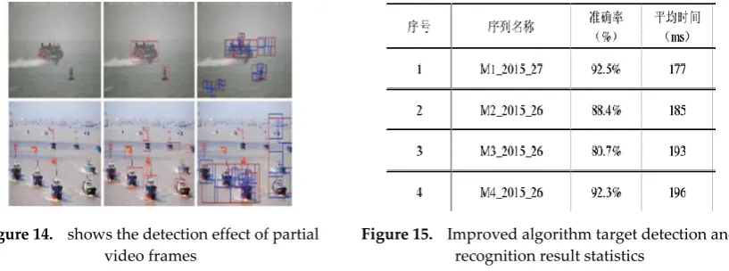
Based on the dark channel algorithm, Shanghai Maritime University presents a method of
187
dehazing for sea hazy images. It uses the mean shift method and edge detection method of
188
embedding confidence for image segmentation of a sea hazy image, and applies the morphological
189
dilation and erosion operations with binarization to extract regional and non-regional sky area in the
190
hazy image, and finally dehazes the sky area with restricted contrast histogram equalization
191
algorithm, and non-sky area with dark channel prior with guided filtering. Experimental results
192
show that relative to the dark channel priority method, the proposed method does not provide the
193
transition area and the phenomenon of color cast in the sky area, and achieves high performance of
194
haze removal[19].
195
Another method of defogging is a sea fog dehazing method based on the physical model of
196
atmospheric scattering. Harbin Engineering University uses the atmosphere [20] to solve the problem
197
of video image quality degradation caused by the scattering of atmospheric particles under sea fog
198
conditions. Aiming at the obvious characteristics of sea image boundary line and large sky area, the
199
image is segmented, the sky area feature is analyzed to obtain the sky brightness estimation value,
200
and the frame difference method background extraction method is used to improve the video by
201
calculating the fog distribution map under the same background. The defogging rate of the image.
202
Compared with several existing terrestrial dehazing methods, the structural similarity (SSIM) of the
203
processed image and the original fog image is smaller than that of Retinex and He, and the image is
204
defogged. better result. At the same time, the processing algorithm takes 32% less time than the
205
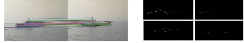
Retinex algorithm and about 48% less than the He algorithm. Based on this, a fast video defogging
206
method based on guided filtering for the unmanned surface vehicles background and target in
real-207
time change state is proposed [21]. In order to improve the video defogging efficiency, the
208
background frame difference method is combined. This method is applicable to single images and
209
video images under sea fog, and is verified by simulation. 9 is the improved video sea fog processing
210
effect picture. It is proved by experiments that the method can effectively improve the video sea fog
211
removal efficiency, the defogging processing speed can reach 5.2 frames/s, and the video defogging
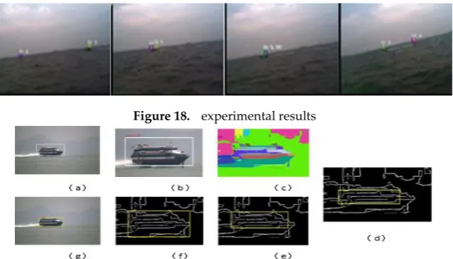
212
effect is good.
213
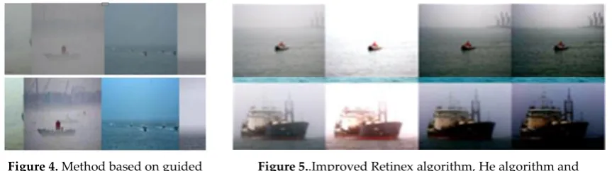
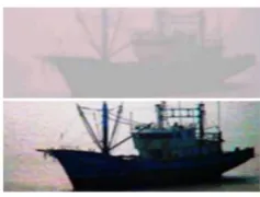
Figure 4. Method based on guided filtering sea fog removal
Figure 5..Improved Retinex algorithm, He algorithm and comparison of the a atmosphere algorithm
At the same time, the Naval Academy also combined the atmospheric scattering physical model
214
to propose a defogging method based on the depth of field of a single video image [22]. The basic
215
characteristics of foggy video images are analyzed from the aspects of contrast attenuation, color
216
histogram and frequency distribution, as the basis for adjusting the parameters in the atmospheric
217
model, and modifying and optimizing the model. The dark primary color value of each pixel is
218
corrected by the similarity of the color between the pixels in the neighborhood of the image, and the
219
transmittance of the traditional dark primary method is improved by estimating the sky brightness
220
interval in the dark primary histogram and selecting a reasonable atmospheric light value. The
221
problem of blockiness breaks through the limitations of the classical gas scattering model on depth
222
of field. The results of processing the foggy and degraded images of multiple scenes show that the
method approximates or exceeds the interactive method and He method in terms of average gradient,
224
edge intensity, information entropy and histogram correlation coefficient. The average gradient is
225
about 50% higher, which verifies the effectiveness and high accuracy of the algorithm.
226
The PLA University of Science and Technology has developed a method of applying wavelet
227
transform to dehaze water surface images [23]. The main method is to use wavelet transform to
228
suppress low-frequency information, and appropriately enhance the scene information in the
229
defogging image; then, based on the SSR color constant algorithm, apply a series of processing such
230
as stretching and color reduction to improve the image brightness. Experiments show that the
231
algorithm has a good visual effect. Fig. 6 is a diagram showing the effect of the picture in the presence
232
of the sea fog taken.
233
Figure 6. Wavelet transform + SSR defogging
In summary, in the research work of water surface image defogging, the following aspects are
234
worthy of research scholars to carry out the work: First, we must improve the adaptive adjustment
235
ability of the algorithm. The current algorithm does not guarantee that it is suitable for all scenes or
236
images, or that you need to manually adjust the parameters. Secondly, the effect of the defogging
237
algorithm needs to be improved. At present, the image defogging technology still has more or less
238
distortion phenomenon, especially in the processing of dense fog images [24,25]. The complexity of
239
the defogging algorithm still needs to be reduced. The existing defogging algorithm, especially the
240
algorithm with good defogging quality of single image, generally has the problem of excessive time
241
complexity. The ideal dehazing algorithm should be applicable to real-time processing of large
242
images, which requires the defogging algorithm to reduce the time and space complexity while
243
ensuring the quality of the defogging.
244
3 Sea-sky line detection
245
Whether for target detection of monocular vision or for target ranging of binocular vision, sea
246
antennas or coastlines are a very meaningful piece of information. When the unmanned surface
247
vehicles sail, most of the images appear in the image are sea antennas, and when the carrier returns,
248
most of the images appear in the image. We refer to the water antenna and the water shore line as the
249
sea-sky line[2]. High-precision detection of water boundaries is critical for unmanned surface
250
vehicles applications. For example, a water antenna can be used to solve stereo camera calibration
251
problems; water boundary detection is sometimes a critical step in surface target detection, which
252
can narrow the search space.
253
College of Electrical Engineering Naval University of Engineering proposes a new method
254
which is based on histogram analysis and linear fitting is proposed[26]. It can obtain the information
255
of pixels near the Sea-sky-line through an analysis of the histogram, and calculating the rough area
256
to get rid of irrelevant pixels in order to extract the sea-sky-line through the method of linear fitting.
The experimental results show that this method has many advantages such as strong robustness,
258
speedy calculation and high practical value. Southwest Institute of Technical Physics presents a
259
texture model by analyzing the texture distributing feature at ocean line area of classical sea-sky
260
images. The textural image is got by using gradient operators. Then the positions of likely
sea-sky-261
line can be obtained by clustering the peak value of gradient[27]. The correct sea-sky-line was
262
detected by comparing the textural parameters of all those positions. The method does not need to
263
perform preprocessing such as line detection and image segmentation, has good adaptability to
264
different scenes through simple gradient calculation and analysis, and can better resist large-area
265
cloud group interference, water surface bright band, strong Interference such as clutter. Nanjing
266
University of Science and Technology detect the sea-sky horizon by examining the approximate
267
image of a Haar wavelet decomposition of the original image. And the equation of the sea-sky
268
horizon is set up, no matter whether the sea-sky horizon is horizontal or not. Since the sea-sky horizon
269
is located, not only the potential area but also the strip direction of noise is got. And it works well
270
when sea-sky horizon line is oblique or in heavy noise[28]. National Defense University proposes a
271
novel method,basedon phase grouping and gray statistics was presented[29].
272
Wang Bo of Harbin Engineering University proposed a sea-antenna detection method based on
273
gradient saliency[30]. The calculation of gradient saliency effectively enhances the linear
274
characteristics of the sea horizon and suppresses various interference factors. The regional growth
275
method is used to detect and identify the sea antenna. Finally, the optical image acquired by the
276
unmanned surface vehicles in the actual sea environment is used. verification. The image sequence
277
detection results in various weathers show that compared with Hough transform, Radon transform,
278
RANSAC straight line fitting and shear wave transform, the accuracy of the proposed method is as
279
high as 95%, which is higher than the above four methods. 11%~27%, Figure 8 shows the sea-antenna
280
detection based on gradient significance. At the same time, the time taken for water antenna detection
281
in each frame is about 50% less than the fastest of the four types of Hough, which proves that the
282
accuracy and real-time of the method used are excellent.
283
Figure 7. Sea-sky detection based on haar wavelet decomposition
Figure 8. Sea-sky line detection based on gradient significance
Finding the region of interest is the current mainstream method for water boundary detection,
284
with the aid of the region of interest to determine the position of the sea antenna. Xiao Zhengmo of
285
Nanyang Technological University selects the region of interest by conversion and cropping, and
286
further processes the region of interest to obtain the position of the water antenna. The sea-sky line
287
detection algorithm was tested by using the image image global sparsity and Hough variation, and
288
the sea antenna detection algorithm was tested using the acquired four image sequence data [31]. By
289
selecting the detected maximum horizontal distance of the horizontal line spectrum to the ground
290
truth value is less than 10 pixels, the average horizontal accuracy is 93.0%. The original image has
high sampling accuracy and fast calculation speed, as shown in Fig 9. However, the real-time effect
292
of this method is inferior to the traditional method, and the actual application effect on the project is
293
not good.
294
Ran Gladstone, Israel's Signal and Image Processing Laboratory, estimates the distance between
295
the target and the camera by detecting the water antenna and using its distance as a reference [32].
296
The method estimates the point of contact between the target and the sea surface by finding the region
297
of maximum stability. Then, the geometry of the earth and the optical properties of the camera are
298
used to calculate the distance. Figure 10 shows the effect of the water antenna detected. The method
299
was tested on several videotapes of sea exercises with an average error of 7.1%.
300
Figure 9. Sea-sky line detection based on global sparsity Figure 10. The detected line is marked as red
National University of Defense Technology Hao Guo applies the Kalman filter to water antenna
301
detection [33], estimates the approximate parameters of the camera pose based on the prediction, and
302
obtains candidate image pixels in a small region of interest around the predicted horizontal position.
303
Then, within the candidate image pixels, the candidate line segments are determined, and the final
304
horizontal line is selected according to the geometric characteristics of the candidate line segments,
305
and FIG.11 is the actual detection result. Bok-Suk Shin et al. proposed a hierarchical random sampling
306
consistency algorithm to detect water antennas [34]. First, the RANSAC is used to estimate the water
307
antenna position in the reduced gradient image, and the neighborhood defining the estimated water
308
antenna is defined as the region of interest, and after detecting the water antenna in the small-sized
309
image, the water antenna is re-projected to the original image. An appropriate amount of image
310
blocks are then sampled in the edge detection image of the region of interest of the original image,
311
and a straight line fit is performed using RANSAC in the image block. Finally, RANSAC is used to
312
aggregate candidate image blocks with smaller variance to calculate the final water antenna. This
313
method solves the difficulties caused by the reflection of sunlight, occlusion, poor light, and
314
staggering in the boundary area. Experiments were carried out in different scenarios of the data set,
315
and the standard Hough transform (HT), least squares (LSO) and standard random sampling
316
consistency algorithms showed that the proposed method HR is more accurate than other traditional
317
methods. Figure 12 compares the accuracy of water antenna detection using different methods. The
318
limitation of the proposed method is that it does not work well for scenes with large noise.
319
In summary, the detection of unmanned water boundaries has a relatively mature method, but
320
they all have their own limitations, mainly the problem of real-time and accuracy have a lot of room
321
for improvement. At present, there are many literatures on the extraction of sea-sky lines, mainly
322
based on the principles of row mapping histogram, gradient transformation, wavelet transform,
323
Radon transform, maximum inter-class variance method, texture feature and Hough transform. And
324
although many research methods have been proposed, most of the methods have not been verified
325
on unmanned surface vehicles, and the practicality remains to be verified. Researchers still need to
326
study in depth to adapt to their characteristics, and to balance real-time and accuracy. Due to the
rapid development of artificial intelligence, the detection of sea-sky lines based on deep learning will
328
become a new research direction in this field, and more excellent methods are expected.
329
Figure 11. Region of Interest and sea-sky line detection results
Figure 12. Comparison of sea-sky line detection accuracy using different methods
4 Research on water surface target detection method
330
Unmanned surface vehicles mainly undertake tasks such as intelligence gathering, surveillance
331
and reconnaissance, mine clearance, anti-submarine, search and arrest, and hydrographic survey.
332
According to the mission requirements, the unmanned surface vehicles should have the ability to
333
detect and identify the surface target, that is, to obtain the position and motion information of the
334
target. With the unique advantage of light vision, in the close-range detection area of the water
335
surface, light visual perception is easier to obtain the position information of the water surface target
336
and the motion information of the target than other means. With the development of related
337
technologies, the surface motion detection technology based on information fusion has become more
338
mature. According to the characteristics of unmanned surface vehicles, it can be equipped with
339
various sensing devices such as cameras, laser radars, infrared sensors, and millimeter wave radars.
340
Different sensors can extract different features for the same target, exert their respective advantages,
341
and integrate detection information to improve the detection effect of moving targets. Therefore,
342
target detection based on multi-sensor information fusion is a development trend.
343
For the problem of direct detection of water surface targets, some researchers have combined
344
the specific characteristics of water surface images for target detection. Harbin Engineering
345
University Wan Lei et al. proposed an automatic detection method for offshore targets based on
346
coastline information for the detection of maritime targets in unconstrained coastal backgrounds, and
347
obtained the target location [35]. The Huff transform is used to perform the voting weighting process
348
to determine the precise position of the coastline. It is proved by experiments that the proposed
349
method can detect the coastline under different tilting states and achieve accurate target positioning.
350
The single frame processing is within 0.2s, with accuracy and accuracy. Rapid. On the basis of this,
351
Zhang Tiedong et al. proposed a weak target detection method based on the visible light sequence
352
image of the sea motion carrier combined with the complex sea-air background image [36]. The
353
Mean-shift segmentation algorithm is used to filter the clustering first. The following figure is the
354
segmentation result. Figure 13 is the automatic detection result of the offshore target based on the
355
coastline information. After that, the largest area area is separated from other areas to binarize the
356
image, and the target extraction is completed. The algorithm has been proved to have good accuracy
357
and real-time performance.
Figure 13. Automatic detection results of offshore targets based on coastline information
Because the surface motion target is significantly different from the information contained in the
359
surrounding environment, some research scholars propose detection ideas based on the difference
360
between the water surface target and the surrounding environment. Chang Li, a national processing
361
laboratory for multispectral information processing, proposes the use of the notion of salientity to
362
obtain salient features, namely the use of target-proposed rapid target detection methods [37].
363
Although there are many environmental noises, the obstacles around the unmanned surface vehicles
364
are very unique, blending objects and significant results, calculating the significant density of each
365
object proposal and eliminating false alarms. The algorithm was tested with several challenging data
366
sets collected in the marine environment. The average accuracy was 82%, and the time per frame was
367
0.268s. The results show that the algorithm has higher accuracy and lower false positive rate. Li
368
Chang of the same laboratory and Cao Zhiguo of Huazhong University of Science and Technology
369
for the rapid detection of surface moving targets, object uncertainty and perspective illumination
370
changes, proposed a rapid surface motion target detection method based on target surface features
371
[38]. The algorithm is tested on several data sets collected in the actual marine environment. Figure
372
14 below shows the effect of partial video frame detection. The results show that the algorithm has
373
the advantage of higher precision. Compare accuracy with the DPM algorithm to measure accuracy
374
and time. In the later period, Li Chang combined the target characteristics and significance on the
375
basis of the two, and eliminated the false targets to get the exact position of the target. The algorithm
376
has better adaptability, and it has a great improvement in both the detection effect of the target and
377
the speed compared with other existing target detection algorithms [39]. According to the data sets
378
collected, the verification accuracy is above 80%.
379
Figure 14. shows the detection effect of partial video frames
Figure 15. Improved algorithm target detection and recognition result statistics
Image sparsity is an important feature of images. Sparse indicates that some large values of
380
coefficients concentrate most of the image. In images that contain surface targets (obstacle), these
381
targets may have a large coefficient, including most of the energy and information of the image, and
contribute to the detection of the target based on sparsity. Xiao Zhengmo of Nanyang Technological
383
University proposed an obstacle detection algorithm based on unmanned surface vehicles by
384
exploring the global sparsity of image blocks [40]. It shows higher accuracy than traditional methods
385
and advanced saliency detection methods. In this method, the sampled image blocks of the sea
386
surface are considered to be the main cluster, and the outliers are regarded as obstacles. The
387
clustering process is based on the global sparsity of each image block, which is sparse in the whole
388
image, but has similar texture information to the sea surface, which is significantly different from the
389
sea surface obstacle. Figure 16 is re-aggregation with features (green) and significant Compared with
390
the method of sex detection (blue), it can be seen that the proposed algorithm (red) is superior.
391
Although the algorithm shows good performance, only grayscale images and texture features are
392
used, and the characteristics of color information of ocean images are not studied. In addition, test
393
data in more complex cases should be collected to study the robustness of the algorithm. On the basis
394
of this, Wang Hao of Nanyang Technological University developed a real-time obstacle detection
395
system. The system is capable of detecting and locating multiple obstacles in the range of 30 to 300
396
meters [41]. In different situations, it is sufficient to detect multiple obstacles and estimate the obstacle
397
position. The detected position is compared with the GPS position recorded on the target ship. Field
398
tests have proven that the system's performance and reliability are excellent. In the later process, a
399
real-time visual remote object detection and tracking algorithm is proposed. Using high-definition
400
images (2736*2192), the object distance is estimated to reach higher precision.
401
Yan Xiao zheng of Nanyang Technological University proposed a real-time vision-based
long-402
distance target detection and tracking algorithm for unmanned surface vehicles. High-resolution
403
images (2736 × 2192) were used in the study to obtain a high-precision target distance[42]. In order to
404
ensure the real-time performance of this high-resolution image, a coarse-to-fine method is proposed.
405
Firstly, the position of the sea-antenna and the target is roughly estimated on the lower-resolution
406
image corresponding to the HD image, and then the target sense is detected. Area of interest. The
407
region of interest is projected onto the original high-definition image, and finally the extracted
408
regions of interest on the high-definition image are stereo-matched in the original image to present
409
more accurate 3D information. In the tracking task, the target tracking based on the 2D image is
410
combined with constraint template matching to calculate depth.
411
Figure 16. proposed algorithm (red) compared with the classic method
Figure 17. Vision-based unmanned surface vehicles target tracking test renderings
The deep learning has raised the detection method of enriching the surface motion target. The
412
research structure has applied the deep neural network to the practical application of surface motion
413
target detection. Wuhan University of Technology, Xie Wei et al. collected the inland river ship image
414
database to establish a ship single multiple detection (SSD) deep learning framework, and achieved
415
high inland ship detection accuracy by using pre-training model parameters to tune and fine-tune
the classification framework. The experimental results show that the recall rate and precision rate of
417
the proposed recognition algorithm can both reach more than 70% under different weather
418
conditions. [43]. The experimental results show that the designed algorithm can successfully output
419
the surface ship detection results, and verify the efficiency and accuracy of the PCANET method by
420
comparing with the CNN algorithm, and prove the superiority of PCANET in feature extraction.
421
Wang Han developed a set of unmanned obstacle detection system based on stereo vision [44]. Figure
422
18 is a test display diagram of obstacle detection and positioning. After field testing, the unmanned
423
obstacle detection system proved to provide stable and satisfactory performance. For high-speed
424
unmanned surface vehicles, the effective range of detection is 20 to 200 meters. Yang Jian, Huazhong
425
Normal University, proposed a monitoring and tracking system based on neural network for water
426
surface targets [45]. The problem of low positioning accuracy of the current CNN-based detection
427
method is solved by using the accurate detection result of segmentation. At the same time, KF is used
428
to track objects of multiple frames to improve efficiency, and the result is smoother than F-R-CNN.
429
And using the improved R-CNN to re-detect the objects in the tracking frame to avoid losing the
430
tracking target, Figure 19 is the specific research process. The experimental results show that the
431
system has the characteristics of high speed, good robustness and high precision. It can locate objects
432
more accurately and stably at the same time, and can be applied to practice in USV.
433
Figure 18. experimental results
Figure 19. (a) initial detection frame (b) area image (c) segmentation image (d-f) process of superpixel combination in the initial detection frame (g) precise detection frame
It is also possible to detect the objects contained in the image by scene understanding and
434
semantic analysis of the water surface image. Matej Kristan of the University of Ljubljana, Slovenia,
435
proposed a new graphical model for the detection of moving targets by unmanned surface vehicles
436
against surface targets through unsupervised segmentation [46]. The model interprets the semantic
437
structure of the marine environment by applying weak structural constraints. Using the Markov
438
random field framework, an efficient algorithm is derived for simultaneously optimizing model
439
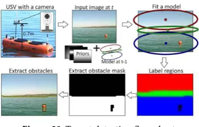
parameters and segmentation mask estimation. The specific principle is shown in Fig. 20.
440
Experiments have shown that the proposed model is superior to the related method and exhibits
441
excellent performance in terms of segmentation accuracy and speed. The limitation is that the
442
algorithm can only get the best results in the YCrCb and Lab color spaces.
Figure 20 .Target detection flow chart
An important use of unmanned surface vehicles for target detection is to plan paths for
444
unmanned surface vehicles and provide accurate environmental information to avoid obstacles. This
445
is a research institute that involves more complex projects and is currently working together to
446
integrate the entire process. Not a lot. South Korea's Jonghong Park uses unmanned surface vehicles
447
equipped with monocular cameras for precise positioning of water targets and self-collision
448
avoidance [47]. In order to estimate the range and orientation of each target relative to the unmanned
449
surface vehicles, the Extended White Motion (CWNA) model of the Continuous White Noise
450
Acceleration (CWNA) model is used to accurately locate the obstacle. Then the obstacle avoidance
451
strategy was proposed according to COLREGS and verified by the water surface test. When the
452
estimated distance between the target and the own ship is less than the predetermined safe distance,
453
the ship changes its heading angle to avoid an emergency collision. The feasibility and effectiveness
454
of the scheme were proved by field experiments. Fig 21 is the result of the detection area and the
455
center point of the DBSCAN, and FIG. 22 is the result of the field experiment based on the visual
456
collision. Terry Huntsberg of the National Jet Propulsion National Laboratory also conducted
457
obstacle avoidance tests based on obstacle information. He proposed a stereo vision system for
458
autonomous navigation of unmanned surface vehicles in a marine environment. The built
459
Hammerhead visual obstacle detection system can generate grid-based hazard maps, and the R4SA
460
control system uses these inputs for sensor-based navigation, including static obstacle avoidance and
461
dynamic target tracking [48]. The team integrated these systems on a number of unmanned surface
462
vehicles and provided experimental results for a vision-based integrated navigation system. In 2009,
463
the Trident's unmanned surface vehicle was tested in the James River Basin.
464
Figure 21. shows the detection result of the detection area and the center point of the DBSCAN.
Figure 22. Field experiment results based on visual collisions
The use of visual information to detect inbound vessels at port terminals is also conducive to the
465
development of unmanned surface vehicles sensing systems. Domenico Bloisi of the Department of
466
Computer and Systems Science at the University of Rome presented an autonomous maritime
467
surveillance system [49]. Vessels are inspected by the Haar classifier to obtain different sizes of
moving targets on the surface of the water, as well as to park stationary vessels near the coast. The
469
unmanned surface vehicles test proves that the method can achieve target detection under different
470
lighting conditions and different positions of the camera. The system is able to provide users with
471
AIS data and add a global view of the visual dimensions. Figure 23 shows the orientation information
472
of the unmanned surface vehicles and the target in the experiment. Tests have shown that the
473
detection method can maintain a speed of 10 fps. The future work is to complete the evaluation of
474
the entire system and add IR data to the data fusion solution to further improve the performance of
475
the system.
476
Figure 23. detects the surface vessel Figure 24. Geographic projection and VTS track. The camera (+) is located in the center of the port
Andrea Sorbara of the Institute of Intelligent Automation Systems of Italy proposed a sensor
477
design for obstacle detection in the marine environment of unmanned surface vehicles. The sensor
478
combines passive and active optics, and Based on the new concept of optoelectronic systems [50], it
479
is designed to be easily installed on small and medium-sized USVs. Its innovation lies in the
480
integration of different sensors, and through the detection steps of Figure 25, demonstrates the ability
481
to detect and identify outstandingly. It has been proved by experiments that the scheme can ensure
482
the navigation accuracy of the unmanned surface of the water surface and the effectiveness of
483
collision avoidance. The unmanned surface vehicle successfully escaped the obstacles detected by the
484
collision avoidance system.
485
(a) (b) (c) (d)
Figure 25. Test System Flow. (a) original image;(b) Histogram obtained with dynamic threshold;System Analysis Results;(d) System Analysis Results
The use of optical vision to obtain the target position and motion information of the unmanned
486
surface vehicles is a necessary condition for the unmanned surface vehicles to autonomously navigate
487
and safely avoid obstacles, which is beneficial to the intelligentization of the unmanned surface
488
vehicles. At present, the main methods are frame difference method, optical flow field method and
489
background subtraction, and improvements in these three methods. The main problems are the target
490
feature robustness and computational complexity. The robustness of target detection is mainly
491
affected by apparent differences within classes and apparent differences between classes. Large
intra-492
class apparent differences and small differences between classes usually lead to reduced robustness
493
of target detection methods [51,52]. The difficulty is that the target can appear anywhere in the image,
494
the target has a variety of sizes and the target can have a variety of different shapes. The
computational complexity of target detection mainly depends on the number of target categories to
496
be detected, the dimensions of the category's apparent descriptors, and the acquisition of a large
497
number of tagged data. Due to the rise of deep learning, the trend of target detection is to adopt the
498
method of deep learning. This method relies on the accumulation of a large amount of training data
499
in the early stage, and the lack of real data for the actual offshore scene of the unmanned surface
500
vehicles, resulting in a model with insufficient training data can not achieve the performance of
high-501
precision detection.
502
5 surface motion target tracking
503
The target tracking method can be classified into a generative method and a discriminant
504
method according to whether the observation model is a generative model or a discriminant model.
505
The most popular generation tracking method in previous years is probably sparse coding, and the
506
recent discriminant tracking method has gradually occupied the mainstream position. The
507
discriminant method represented by correlation filtering and deep learning has also achieved
508
satisfactory results [53]. Surface motion target tracking is a task that is full of various challenges,
509
mainly because the surrounding environment of the surface moving target is full of various
510
disturbances and changes frequently, or the shape and size of the moving target itself are diverse in
511
the image sequence. Therefore, accurately identifying and tracking moving targets in a complex
512
water environment becomes a problem with various effects. The following are some of the main
513
challenges in surface tracking: (1) occlusion is one of the most common challenges in surface tracking,
514
and occlusion is divided into partial occlusion and full occlusion. There are usually two ways to solve
515
partial occlusion: use the detection mechanism to determine whether the target is occluded; divide
516
the target into multiple blocks, and use the block that is not occluded for effective tracking. (2)
517
Deformation is also a major problem in the tracking of surface targets. The shape of the surface
518
moving target is constantly changing, which usually causes the tracking to drift. A common way to
519
solve drift problems is to update the apparent model of the target. (3) Multi-target interference refers
520
to the fact that there are very similar targets around the surface target to be tracked that cause
521
interference to the tracking. Commonly used to solve such problems is the data trajectory, the general
522
trajectory of the prediction motion or the use of a large number of sample frames around the target
523
to update the classifier. (4) Scale change is a phenomenon in which the scale of the water surface is
524
changed from far and near or from near to far. The size of the target frame is also a challenge in target
525
tracking. Of course, in addition to the above common challenges, there are other challenging factors:
526
lighting, low resolution, motion blur, fast motion, beyond view, rotation, and so on. All of these
527
challenge factors together determine that surface tracking is an extremely complex task.
528
Bok-Suk Shin of the Software Research Institute of Hanyang University in Korea developed a
529
real-time visual navigation and remote target detection and tracking system for unmanned surface
530
vehicles for target detection and target tracking of unmanned surface vehicles under severe
531
conditions such as large waves and foggy water. It is the effect of the detection box tracking part of
532
the frame when the distance is about 200m. According to the test, the target detection and tracking
533
distance of the system is up to 500 meters [54]. In the tracking module of the system, the target
534
tracking matching is performed based on the two-dimensional image of the constraint template, and
535
the specific principle is shown in FIG. 26. The Korea Marine Robotics and Intelligent Mechanical
Engineering Laboratory Eternal Hall uses a monocular camera mounted on an unmanned surface
537
vehicle to perform accurate measurement and autonomous tracking of surface ship distances [55].
538
Automatic extraction of target features and tracking filtering algorithms for visual detection and
real-539
time tracking. This information is transmitted to the target tracking system by computer vision to
540
obtain the position and range information of the target relative to the ship. The distance between the
541
obtained camera and the target is used to further calculate the exact distance between the two, and
542
the detection servo program is designed to improve the observability of the target tracking filter. The
543
feasibility and performance of the scheme were verified by two offshore unmanned surface vehicles.
544
Ran Gladstone et al. [56] of the Department of Electrical Engineering at the Technion Institute of
545
Israel also used a monocular camera to estimate and track the target position, and the method takes
546
into account the limitations of the USV in the marine environment, detects the sea level and uses its
547
distance as a reference. The point of contact between the target and the sea surface is detected by
548
finding the maximum stable extreme value region (MSER), and then the horizontal line and the
549
optical characteristics of the camera are used to calculate the distance. The method is tested on
550
multiple marine video lenses, showing that the average absolute error relative to GPS is in the range
551
of 4.8% to 9%, and the overall average error is 7.1%. Figure 28 below shows the original image
552
acquired and the algorithm detects Water antenna and target area. The test has been run for about
553
0.5-2 seconds per frame, written in MATLAB, running on a standard quad-core Windows PC, and
554
can be ported to USV for practical applications.
555
Figure 27. shows the results of testing and tracking challenging frames
Figure 26. Template matching for target distance estimation
Figure 28. Water Antenna and Target Detection
Serdar Cakır and others at the University of Adollo used a feature selection and evaluation
556
mechanism to achieve accurate tracking of surface targets. The performance of the feature set is
557
compared using a support vector machine, and those feature sets that yield the highest detection
558
performance are used in the covariance-based tracker [57]. It is observed that the proposed tracking
559
scheme is capable of tracking sea surface targets with reasonable accuracy, and the results show that
560
the gradient-based features are along with various position and intensity values. The performance of
561
the proposed tracking strategy is also compared with some well-known trackers, including
562
correlation Kanade-Lucas-Tomasi features and trackers based on scale-invariant feature transforms.
Experimental results and observations show that the proposed target tracking scheme is superior to
564
other trackers in maritime surveillance scenarios.
565
There are also research institutes that apply new information fusion methods to surface target
566
detection and tracking tasks, mainly based on fusion of vision and lidar or integration of vision and
567
GPS. Nanyang Technological University Xiao Zhengmo et al. [58] proposed a method based on stereo
568
vision for static obstacles in unmanned surface vehicles. In this system, the monocular camera is
569
integrated with GPS and compass information. The proposed method avoids the complicated
570
calibration work and huge equipment layout problems in the previous binocular stereo perception
571
system, and can obtain more through the USV movement. The baseline is thus increased by 500 to
572
1000 meters, as shown by the straight line in Figure 29. The actual position of the detected static
573
obstacle is reconstructed while the USV is traveling, and then the obstacle map model is constructed,
574
and the final reconstruction result is synthesized by multi-frame weighting. Tests were performed on
575
the test data set. Figure 31 is a flow chart of the obstacles in the test. The results demonstrate the
576
practicability of the system. D. Hermann ∗ R of the Technical University of Denmark directly
577
combines radar and visual information to develop a target tracking system for high-speed unmanned
578
surface vehicles that can be used for unmanned surface vehicles operating at 30 m/s [59]. Since the
579
detection distance of the laser radar is closer than that of the monocular camera, the detection distance
580
of this method is closer than that of Xiao Zhengmo's method, and the obstacle can only be detected
581
in real time within the range of 175 meters. The obstacle detection process is shown in Figure 30. The
582
attitude-based statistical measurement helps to further reduce clutter, and the computer vision level
583
detector can achieve highly accurate attitude estimation. The position and attitude estimation based
584
on Kalman filter is designed and implemented, and the sea wave interference can be minimized to
585
accurately track the moving target trajectory.
586
Figure 29. ORB feature detection, tracking and matching Figure 30. Obstacle detection steps
Figure 31. The straight line in the image is connected to the obstacle map (middle) produced by the USV (Seq-3)
Zhang Xiangli of Shanghai Jiaotong University proposed a new radar clustering method for the
587
tracking of unmanned surface vehicles on surface ships. In the process of integrating the data from
588
cameras and radars to identify and track vessels in lakes [60], namely in Figure 32 The spatial angle