Article
Belt-Driven Open Source Circuit Mill Using
Low-Cost 3-D Printer Components
Shane Oberloier 1 and Joshua M. Pearce 1,2,3*
1 Department of Electrical and Computer Engineering, Michigan Technological University, Houghton, MI 49931, USA
2 Department of Materials Science and Engineering, Michigan Technological University, Houghton, MI 49931, USA
3 Department of Electronics and Nano engineering, School of Electrical Engineering, Aalto University, Espoo, Finland
* Correspondence: [email protected]; Tel.: +1-906-487-1466
Abstract: Barriers to inventing electronic devices involve challenges of iterating electronic designs due to long lead times for professional circuit board milling or high-costs of commercial milling machines. To overcome these barriers this study provides open source (OS) designs for a low-cost circuit milling machine. First, design modifications for mechanical and electrical sub-systems of the OS D3D Robotics prototyping system are provided. Next, Copper Carve, an OS custom graphical user interface, is developed to enable circuit board milling by implementing backlash and substrate distortion compensation. The performance of the OS D3D circuit mill is then quantified and validated for: positional accuracy, cut quality, feature accuracy and distortion compensation. Finally, the return on investment is calculated for inventors using it. The results show by properly compensating for motion inaccuracies with Copper Carve, the machine achieves a motion resolution of 10 microns, which is more than adequate for most circuit designs. The mill is at least five times less expensive than all commercial alternatives and the material costs of the D3D mill are repaid from fabricating 20-43 boards. The results show that the OS circuit mill is of high-enough quality to enable rapid invention and distributed manufacturing of complex products containing custom electronics.
Keywords: 3-D printing; circuit milling; circuit design; distributed manufacturing; electronics; electronics prototyping; free and open-source hardware; P2P; P2P manufacturing
1. Introduction
Domestic commerce started in the U.S. as household-level distributed manufacturing (DM) [1,2]. However, standardized high-volume, centralized mass production overtook it with the first industrial revolution and has made up the majority of domestic production until the present [3-8]. Recently many authors have argued that DM with 3-D printing can reduce costs for consumers for a wide range of products [9-13]. This can be accomplished with 3-D printing businesses manufacturing and selling products to consumers or other businesses [14-17]. As examples of the growing prevalence of this trend, 3-D printing stations are being added to commercial chains such as Home Depot [18] and the United Postal Service [19]. However, free and open source hardware (FOSH) development [20,21], provides a profitable investment for household-level DM with self-replicating rapid prototyper (RepRap) 3-D printers [22-24]. RepRap-centered DM of high-end products (e.g., scientific tools) has been shown to significantly reduce costs [25-30] and provides a high return on investments (ROIs) for science funders [31,32]. In addition, this model is being adopted by the average American consumer and the number of free pre-designed 3-D products of all kinds is also growing rapidly because of the economic benefits of DM for both DIY kits [33] as well as plug-and-play commercial 3-D printers [34]. Most strikingly, a recent study showed commercial 3-D printers
were economically viable even when used for only fabricating hard plastic toys [35] or flexible products from relatively-expensive specialty 3-D printing filament [36].
However, currently DM has matured primarily in mechanical products and components because of widespread cost declines due to the open sourcing of 3-D printing [37]. Open source electronics has created many successful companies, because various open hardware business models work well with hobbyist electronics [38], however, DM of electronics is not as mature. For example, the fabrication stations at Home Depot [18] and the U.S. Postal service [19] only include mechanical prototyping, but do not offer electronics prototyping. The lack of maturity in DM of open source electronics is a limiting factor in the complexity of products. There are two primary reasons for the slow adoption of DM circuit boards. First, there is a lack of unified sources for pre-designed projects, equivalent to sources for 3-D printable models like MyMiniFactory [39], Thingiverse [40], and YouMagine [41] or the search engine Yeggi [42]. There are some sources of FOSH circuitry such as Open Circuit Institute [43] and Open Circuits [44], though they have not been widely adopted. Most importantly, there are no widely recognized low-price FOSH circuit milling machines equivalent to the RepRap 3-D printers that can be built by consumers or purchased from companies like Lulzbot [45], re:3D [46] and Ultimaker [47]. The existing mills on the market are either prohibitively expensive [48], or lack proper documentation and are difficult to tune due to reliance on closed source designs [49]. The current traditional methods of circuit board procurement (ordering from fabrication shops) can be improved on in terms of both lead time and cost [50] with a low-cost FOSH circuit board mill. This study provides open source designs for a low-cost circuit-milling machine in order to overcome these limitations and enable DM of complex products containing custom electronics. The goal of the design is to provide an enabling device for inventors to make novel electronic designs by leveraging the same open source and peer to peer (P2P) methodologies found to be so successful in 3-D printing. The mill is thus designed around the open source D3D Robotics prototyping system [51], because of a low part count, scalability, and ability to be DM. First, this study provides the design modifications for the mechanical and electrical system of the D3D system. Next, a custom graphical user interface (GUI) open source software called Copper Carve is developed to enable circuit board milling. Copper Carve is minimalist in nature and made to be easily modified for other applications although here the implementations of two critical features, backlash compensation, and substrate distortion compensation are discussed for their importance to circuit board milling. The mathematics of these features are detailed and discussed. The performance of the open source circuit mill is quantified and validated for 1) positional accuracy, 2) quality of cut, 3) feature accuracy and 4) distortion compensation. Finally, the cost of the machine is considered, as well as a return on investment (ROI) analysis for using it.
2. Materials and Methods
Figure 1. The FreeCAD model of the open source circuit mill.
2.1. Construction
2.1.1. D3D Design System
The D3D construction has already been proven by Open Source Ecology (OSE) [52], as an effective FFF 3-D printer [51]. The system itself consists of few original components for motion axes; motor pieces, idler pieces, and carriage pieces (Figure 2). A breakdown of the quantities of each piece used can be found in the machine bill of materials (BOM) available https://osf.io/mf78v/.
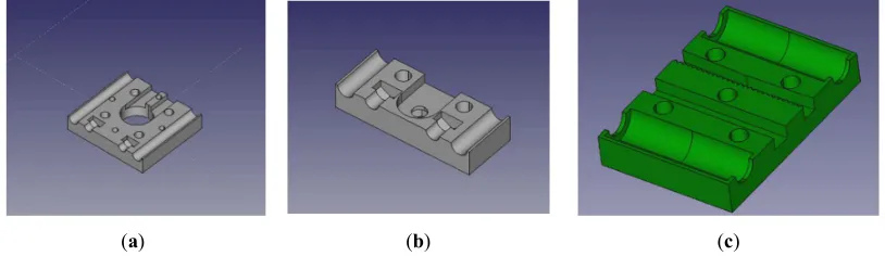
(a) (b) (c)
Figure 2. The 3-D printed component models for the D3D design system. The rendered designs of the (a) motor mounting block, (b) bearing mount block, and (c) carriage block are shown.
The mill is built inside of a 406.4 mm (16 inch) cubic space frame for rigidity, and ease of mounting. The D3D building blocks are all designed with short sockets for 10 pound neodymium magnets [54], which are used to easily connect and reconfigure components like the end stop interfaces. Magnets are also used to fixture the movement axes to the space frame.
2.1.3. Custom Adaptions
A few custom components must be designed to facilitate the tool spindle (Figure 3a), and board holder (Figure 3b). In addition, each axis must be driven by two stepper motors to facilitate the loads associated with carrying the tool spindle, as well as milling into material. In addition, the Z axis requires a higher current supply than is on the RAMPS driver board, so a TB6600 based driver [59] is selected and split to two stepper motors.
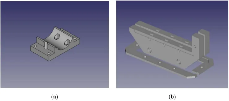
(a) (b)
Figure 3. (a) The spindle mount model. (b) The board holder model.
The last modifications are to add four compression springs to the Z axis linear rails. They are used to cancel the 1 kg of weight associated with the tool spindle. Since D3D is based around belt driven axes, the failure mode of the loaded Z axis would be to fall until it collides with the cutting surface – effectively breaking cutting tools or ruining the work piece. The addition of the springs mitigates this issue and changes the failure mode to lift the spindle or, at least maintain its position (when friction in the belt matches the forces caused by compressed springs).
2.2. Software – Copper Carve
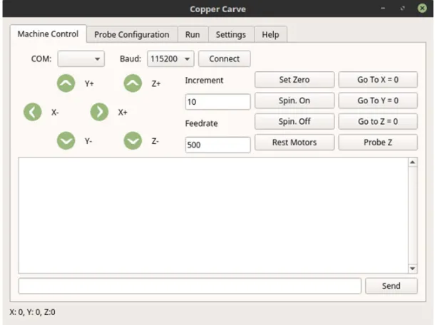
Figure 4. The machine control interface of Copper Carve.
2.2.1. Backlash Compensation
The first critical feature needed for PCB milling implemented in Copper Carve is backlash compensation. Mechanical backlash is a phenomenon caused when a movement axis changes direction. It is the maximum distance through which a mechanical component can be moved in one direction without applying appreciable force [62]. For example, as the drive belt and pulley have tolerances between their teeth, the pulley will “slip” a finite and predictable amount when moving to push against the reverse sides of the belt teeth. Backlash causes movement axes to move slightly smaller distances than commanded. This error can cause significant cutting errors when milling fine features such as completely removing 0.5 mm circuit traces.
There are two necessary steps to compensate for backlash: 1) detecting backlash, and 2) injecting movement instructions to accommodate the physical limitations of the system. Since all motion commands are sent through Copper Carve, backlash can be predicted by examining the sequence of sent G-Code commands. The algorithm is straightforward and detailed in pseudocode below.
If Motion Command For Each Direction
If Direction != Previous Direction Call Compensate for Backlash End If
Store Direction End For
End If
Once backlash has been detected, all other operation must be put on hold to allow the serial port to become available for compensation G-Code. This is detailed below in pseudocode.
Store Location
SendGCode(G91)//Relative Movement For Each Direction
If Backlash Present
End For
SendGCode(G90)//Absolute Movement
SendGCode(G92 Location)//Reset to Measured Location
2.2.2. Substrate Distortion Compensation
Commonly, inexpensive copper clad fiberglass used as a circuit board base material has a large degree of warpage as illustrated in Figure 5 (e.g. may vary in height by 2 mm). This warpage is considerable relative to the isolation routing cut depth of 0.1 mm. Because of this distortion, a lack of compensation will cause a failure to cut, or an increased cut depth – both of which will render the work piece unusable.
Figure 5. An illustration of substrate deformation.
This warpage can be compensated for by adjusting G-Code files to follow the measured Z axis topology. This topology can be measured automatically using the cutting tool as a continuity probe for the digital input on the RAMPS board. An alligator clamp is used to connect positive voltage to the cutting tool, and another clamp is used to connect the substrate to the digital input. By default, Marlin reports the location that the digital input is triggered (the digital input is configured as a Z end stop) and halts motion. Using this concept, paired with automated movement, height data can be collected for a grid of points of resolution and size determined automatically by Copper Carve (although it can still be modified by the user).
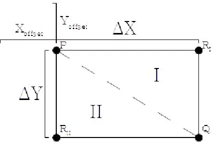
Once the topology is measured, the G-Code file can be transformed to conform to the measured mesh. This is accomplished by applying 3-D linear interpolation [63]. To start, assume a 2-D array of measured Z height data evenly spaced by ∆X and ∆Y. Four points P, Q, RI, and RII define a rectangular
region (visualized in Figure 6) that is offset from the reference origin (i.e. if P is(0,0,Z), then Xoffset and
Yoffset will be 0).
Figure 6. A sketch defining the regions and points used for 3-D linear interpolation.
X
offset≤ X ≤ X
offset+
∆ X
…(1)Y
offset≤ Y ≤ Y
offset+
∆ Y
…(2)Once a point is confirmed to be within the rectangular region, it must next be in sub region I or II. This is important because a plane can only be constrained by 3 points. The interpolation will always use P and Q, but it must be determined whether RI or RII is to be used. The point is in sub region I if
the following inequality is true. This will indicate that RII must be used for the interpolation.
X ΔX>
Y
ΔY …(3)
If the above inequality is not satisfied, then the point is in sub region II, and satisfies the following relation. RII must be used.
X ΔX≤
Y
ΔY …(4)
Once the location of the point in the height array is determined, the interpolation process can begin. First, define the points used for interpolation:
P=
(
X1, Y1, Z1)
…(5)Q=
(
X2, Y2, Z2)
…(6)R=
(
X3,Y3, Z3)
…(7)From these three points, two vectors can be defined:
1 1
1
2
X
,
Y
Y
,
Z
Z
X
=
PQ
2
2
…(8)1 1
1
3
X
,
Y
Y
,
Z
Z
X
=
PR
3
3
…(9)Now it is possible to find the normal vector formed by PQ and PR. This can be done by carrying
out the cross product:
1 3 1 3 1 3 1 2 1 2 1 2Z
Z
Y
Y
X
X
Z
Z
Y
Y
X
X
k
j
i
=
PR
PQ
=
n
…(10)The value of this determinate is found to be:
n
=
(
Y
2− Y
1)(Z
3− Z
1)i
+
(
Z
2− Z
1)(X
3− X
1)
j
+
(
X
2− X
1)(Y
3−Y
1)k −
(
Y
2− Y
1)
(
X
3− X
1)k −
(
Z
2− Z
1)(
Y
3−Y
1)
i−
(
X
2− X
1)(Z
3− Z
1)j
…(11)
In order to keep equations orderly, short hand representations are defined for ´i, ´j , and k´
components of the above equation:
Y
Y
Z
Z
Z
Z
Y
Y
i
=
L
2
1 3
1
2
1 3
1 …(14)
Z
Z
X
X
X
X
Z
Z
j
=
M
2
1 3
1
2
1 3
1 …(15)
X
X
Y
Y
Y
Y
X
X
k
=
A 3-D plane can now be defined given the normal vector and a point on the plane, which is
assumed to be our point undergoing adjustment (X,Y,Z), where X and Y are known, and Z is a known
value that will be modified.
X
X
2
+
M
Y
Y
2
+
N
Z
Z
2
=
0
L
…(17)Finally, solving for Z, a solution is attained:
Z
=
− L
(
X − X
2)
− M
(
Y − Y
2)
N
+
Z
2…(18)
Using equation 18, each G-Code position can be modified to conform to the measured height mesh.
2.2.3. Usage of Timers
In an attempt to keep the code of Copper Carve as comprehensible as possible, QT timers are implemented to handle long or continuing processes such as G-Code streaming or the auto leveling procedure. The timers are used to break up the execution of a sub process and allows for multiple processes to be executed in a parallel and scheduled manner. These same processes could be handled with multi-threading methods, however the implementation in QT would not be easily comprehensible by the lay user.
2.2.4. Auto-Replace Functionality
Though Copper Carve is made to directly interface with the D3D mill, some considerations have been made. Each G-Code command feeds through an auto-replace function that references a file “substitutions.txt”. This can be used to alter G-Code based on which CAM software is being used, or which firmware the target machine contains.
2.3. Mill Usage Workflow
The mill has a specific set of constraints that define minimum specifications of the designed circuit board. In this section, a process is detailed to insure manufacturing that meets these specifications.
2.3.1. Board Design
It is recommended that circuit boards are designed in KiCAD [64], since the software is FOSS and fits well with the toolchain. It is required to have a minimum trace spacing of 0.2 mm and a minimum trace width of 0.5 mm. Any smaller trace width will result in the trace being cut completely off of the board.
Once the board is designed, the auxiliary axis must be placed near the circuit board (preferably in the bottom left corner of the edge.cuts layer) in order to reduce any large locational offset from the origin.
2.3.2. FlatCAM
2.4. Validation
Circuit board milling requires tight tolerances, otherwise the board will likely malfunction. Because of this, the machine must be tightly calibrated and characterized.
2.4.1. Positional Accuracy
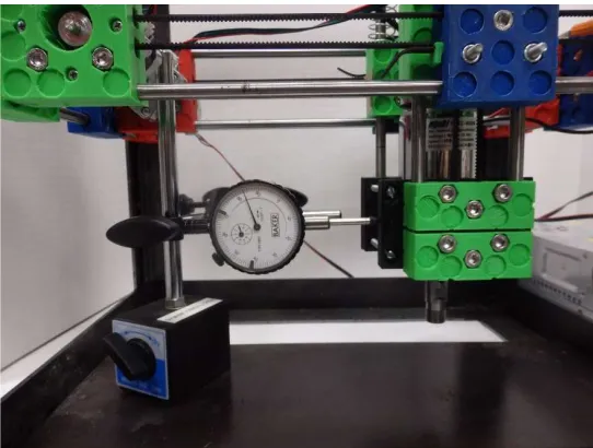
First, the positional accuracy of each axis must be measured. This can be done with a dial indicator set up similar to Figure 7.
Figure 7. Setup of dial indicator for measuring backlash on X-axis
First, the axis is jogged a small value (1 mm) in the positive direction. The indicator is zeroed, then another positive movement is called of a known value. The actual movement is measured and compared. If there is a discrepancy between the two, the steps per mm value for that axis must be adjusted using the M92 command.
Using the same dial indicator setup, the backlash can be measured; but only after the steps per mm value has been validated. To measure backlash, the position is moved in the negative direction a small value (1 mm). The indicator is then zeroed, and the axis is jogged in the positive direction. The difference between command and the measured distance is the backlash value. This value is placed in Copper Carve’s option screen for each axis. With these values updated, the same test can be performed, and if the compensation is successful, there should be no difference between the movement command and the measured movement.
2.4.2. Quality of Mill Cut
A quality cut is defined as a non-destructive cut in the substrate with minimum burring on the copper edges. This is observed both visually, and with an Olympus PME3 optical microscope, using 50X magnification.
2.4.3. Feature Accuracy
Trace width can be a critical dimension, so it is important that their parameters appear on the board as designed. Using an optical microscope, a known trace width can be measured and compared with the intended value. If the measurement is off this can indicate that either the steps per mm, or backlash values were not properly calibrated.
be thinner than the left rectangle. Data gathered from this experiment will show both feature variation, and compensation effectiveness.
Figure 8. A test pattern to verify feature repeatability and backlash compensation effectiveness.
2.4.4. Distortion Compensation Accuracy
The distortion compensation can be observed by introducing an extreme situation. The copper clad fiber glass is fastened to a piece of wood, cut to set the board at a 10 degree angle to the cutting surface. A test pattern is then milled, and observed for Z axis accuracy (i.e. under or over-cutting)
3. Results
3.1. Overall Results
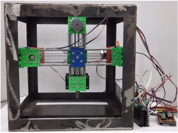
Figure 9. An image of the completed circuit mill
3.2. Positional Accuracy
The positional accuracy of the machine is found to be suitable for the purpose of cutting most circuit board designs. Thanks to properly implemented motion compensation techniques, the machine step resolution is at the hard limit of 0.01 mm for the X and Y axis, and 0.008 mm for the Z axis. The overall machine characteristics are shown in Table 1.
When measuring machine backlash, a dial indicator can allow for accurate measurements up to 0.0254 mm. This value cannot be directly input into Copper Carve, however. Instead, the value must be some multiple of the resolution. This is because the stepper motors cannot physically make a “fraction” of a step. Once the values are measured to the fullest accuracy of the dial indicator, they are fine-tuned incrementally by cutting the test pattern in Figure 8, until the rectangles have identical widths.
Table 1. Motion specifications for the circuit mill
3.3. Quality of Mill Cut
It is desirable to minimize post processing of the boards. One large post processing step is sanding the circuit board to rid the copper cut edges of burrs. By sweeping different cutting feed rates and depth, an optimal configuration can be found. The following samples in Figure 10 are all analyzed visually for the amount and size of burrs present. In this case, it appears operating at a feed rate of 50 mm/min and a cutting depth of 0.2 mm yields the fewest, and smallest burrs
(a) (b)
(c) (d)
Figure 10. Top row from left to right: (a) Feed rate of 50 mm/min, plunge depth of 0.1 mm, (b) Feed rate of 100 mm/min, plunge depth of 0.1 mm, (c) Feed rate of 150 mm/min plunge depth of 0.1 mm, (d) At 50 mm/min, plunge depth of 0.2 mm
Motion Parameter X Axis (mm) Y Axis (mm) Z Axis (mm)
Resolution 0.01 0.01 0.01
Backlash 0.252 0.075 0.1
3.4. Feature Accuracy
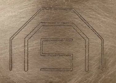
A semi-octagon shape is cut into the copper with a copper trace of widths 0.5 mm and 1 mm. An octagonal shape is chosen to view all common cutting orientations (Figure 11). The minimum width of each feature is measured and compared with the target in Table 2. The width of the cut is also measured and used to adjust the error percentage. This adjustment is made by subtracting the error of the nominal cut width (0.2 mm). This shows that if proper adjustments are made in the CAM software, the indicated error can be achieved.
Figure 11. An image of the octagonal shape used to verify feature accuracy.
Table 2. A comparison of feature accuracies at different cutting speeds.
Cutting Speed Width of 0.5 mm trace 0.5mm Trace% Error of Width of 0.2 mm Cut % Error of 0.5 mm Trace Adjusted
50 mm/min 0.40 mm 20% 0.25 mm 10%
100 mm/min 0.35 mm 30% 0.35 mm 0%
150 mm/min 0.20 mm 60% 0.40 mm 20%
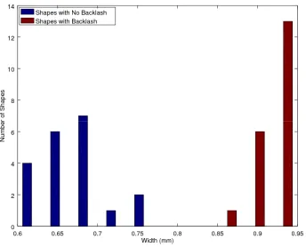
The 20 patterns for X and Y are milled according to Figure 8. The widths of both the control (right rectangle) and variable (left rectangle) are measured in ImageJ [73] by analyzing a photograph taken with an Olympus Stylus digital camera and a reference scale. The results are displayed in a histogram to demonstrate the distribution of widths of the control and variable rectangles.
Figure 12. A histogram of feature widths measured on the X axis.
Figure 13. A histogram of feature widths measured on the Y axis.
3.4. Distortion Compensation
Figure 14. The resultant circuit board which was milled on a 10° incline
Figure 15. The rendered tool path in the XY axis
Figure 16. The rendered tool path in the XZ axis.
4. Discussion
4.1. Open Source as Development Platform
processes. Now the mill explored in this paper can act as an enabling device for encouraging electronics-based invention and the proliferation of DM of open source electronics.
4.2. D3D and Other Applications
The circuit mill explored in this application are one many potential applications of the D3D design system. The same setup could easily be scaled to mill large circuit boards. Copper Carve would require no adaptions to control the larger machine. The machine could also easily be adapted to hold different tools, such as a suction nozzle, making the machine into a pick-and-place tool. The machine could be adapted to utilize a syringe pump [68], which could then be used as a solder paste applicator. The mill, paired with the two bespoke hypothetical machines could act as an entire tool chain to fabricate, and assemble circuit boards, furthering the capabilities of DM at the home, fablab, or small business-levels.
4.3. D3D and Other Applications
Copper Carve is built around the philosophy that open source software should be coded in a way that the target audience can make meaningful modifications to the software. This philosophy requires a skilled programmer to prefer lower level (potentially more complex) solutions, than efficient solutions that invoke obscure or higher-level functions. For example, Copper Carve works for an electronics mill. Typical users of the mill will be electrical engineers, students, inventors and hobbyists. Therefore, it makes sense to consider what kind of modifications the target audience may be making, and what level of programming they may be familiar with. That is why it why Copper Carve does not utilize multi-threaded process, as they require a relatively high knowledge of computer science to properly utilize and modify. A core group of hardy functions, such as SendGCode() are established so they can easily be implemented for purposes such as scripted buttons, or custom processes by the target audience.
4.4. Market Comparison
Commercial circuit board milling machines can cost as much as 3,199 USD [69], which is comparatively expensive in regard to the D3D mill explored in this study. All mills have identical resolutions, and though the maximum speeds seen in commercial systems can improve cutting times, they are limited by the maximum feed rate allowed by the cutting tool, which is well below 1,000 mm/min. Thus the maximum travel speeds are not a major advantage in real-world milling. The final category compared in Table 3, max milling speed, is thus a non-issue when considering the maximum allowable speeds used while milling. This high speed found in other devices is only useful in manual jogging operations, which is a small part of the overall operation. Commercial alternatives are often shipped assembled and ready to use, but because of that, are not scalable nor easily maintainable in cases of a part breakage. The cost of the D3D mill is for the materials only.
Table 3. A comparison of commercial circuit mills to the D3D mill.
Name Price (USD) Resolution (mm) Working Area Max Travel Speed (mm/min)
D3D Mill* 500 0.01 140x200 1,000
Othermill [69] 3,199 0.01 140x114 2,600
Prometheus [70] 1,799 0.01 160x100 3,800
DWR-0906 [71] 1,495 0.01 220x160 2,500
3D Nomad [72] 2,499 0.01 203x203 2,500
* Materials costs only.
mechanical assembly. Once the mill is assembled, basic knowledge of mechanical measurements is required in order to validate axial motion.
The price of each mill also weighs heavily on their respective return on investment (ROI). For this analysis, it assumed that unique 100 mm X 80 mm single layer circuit boards are being manufactured. Based on quotes generated from many PCB fabrication sources [50], a board can be ordered for 12.22 USD, if 27 day shipping is selected. From the same source, a board can be ordered for 25.36 USD if 10 day shipping is selected. The labor costs in using the D3D system are relatively trivial and the system does not need to be monitored during fabrication of a circuit. The energy use during the milling of a standard board was 0.5 kWh, and therefore the energy costs were also ignored. Thus, the only consumable material for the D3D circuit mill is the copper-clad fiber glass, which can cost as low as 0.42 USD [74]. Simply dividing the cost of the mill by the cost per board less the cost to produce on the D3D mill, 43 boards (27 day shipping) or 20 boards (10 day shipping) must be produced in order to recoup the investment for the material costs of the D3D Mill. Compared to commercial alternatives, this can be as 6 times as many boards (258 27-day boards, 120 10-day boards). Although, the use of DM for circuit manufacture will cost less with any of the systems in Table 3, the most valuable asset of DM is the quick turnaround delivered by circuit mills: 2 to 3 hours compared to a minimum of 10 days. This allows inventors and circuit designers to quickly iterate on designs of new boards.
Milling 43 boards is a highly achievable feat during the lifetime of the mill. For example, the base power meter used to monitor an open source home includes 11 boards [75]. With this single project, the mill has already paid for a quarter of its BOM cost. Also, the design process itself for perfecting a new invention is likely to go through multiple iterations and revisions. There are also many cases where the mill could be used as a communal tool, such as research laboratories, fablabs or makerspaces. In all cases, the 43 board threshold can be met in a very short span of time.
4.5. Additional Applications and Future Work
The D3D circuit mill has added utility that has not yet been explored. The mill can be used to cut out 2-D components from wood, or plastics. Additionally, the mill can be used to engrave many materials from wood, plastic, and most metals. Due to the relatively low torques the mill is designed for, it is likely that these tasks can be achieved by using small cut depths, and lower feed rates.
In addition to exploring additional applications of the milling machine, Copper Carve can be modified to have many desirable features; such as tool path preview, motion optimization, height map output, and multi-machine communication (for large production systems).
5. Conclusions
The open source D3D based circuit mill has proven to be a fully-functional circuit board mill that is constructed entirely on open source platforms. By properly compensating for motion inaccuracies with the open source Copper Carve, the machine has achieved a motion resolution of 0.01 mm, which corresponds to the step size of the stepper motor. The mill is at least five times less expensive than all commercial alternatives, with manufacturing capabilities that can fabricate by most design standards. This allows the materials costs of the D3D mill to be recouped in as little as 20 boards while offering users several hours turnaround time between design iterations for inventors instead of 10 days.
Author Contributions: Conceptualization, Shane Oberloier and Joshua Pearce; Formal analysis, Shane Oberloier and Joshua Pearce; Methodology, Shane Oberloier ; Resources, Joshua Pearce; Software, Shane Oberloier ; Validation, Shane Oberloier ; Writing – review & editing, Shane Oberloier and Joshua Pearce.
Funding: This research received no external funding.
References
1. Tryon, R.M. Household Manufactures in the United States 1640–1860: A Study in Industrial History; University of Chicago Press: Chicago, IL, USA, 1917.
2. Sokoloff, K.; Villaflor, G. The Market for Manufacturing Workers. In The Market for Manufacturing Workers during Early Industrialization: The American Northeast, 1820 to 1860; Goldin, C., Rockoff, H., Eds.; University of Chicago Press: Chicago, IL, USA, 1992. DOI: 10.3386/h0028
3. Hounshell, D. From American System to Mass Production, 1800–1932; Johns Hopkins University Press: Baltimore, MD, USA, 1984. ISBN 978-0-8018-3158-4
4. Fine, C.; Freund, R. Economic Analysis of Product-Flexible Manufacturing System Investment Decisions; Massachusetts Institute of Technology: Cambridge, MA, USA, 1986; pp. 1757–1786.
5. Wilson, J. Henry Ford vs. Assembly Line Balancing. Int. J. Prod. Res. 2013, 52, 757–765.
6. Kravis, I.; Lipsey, R. Towards an Explanation of National Price Levels; Working Paper Series 1034; National Bureau of Economic Research: Cambridge, MA, USA, 1982. DOI: 10.3386/w1034
7. Lipsey, R. Challenges to Home- and Host-Country Effects of Foreign Direct Investment. In Challenges to Globalization: Analyzing the Economics; Baldwin, R.E., Winters, A., Eds.; University of Chicago Press: Chicago, IL, USA, 2004. ISBN 0-262-03615-4
8. Bain, J. Economies of Scale, Concentration and the Condition of Entry in Twenty Manufacturing Industries. Am. Econ. Rev. 1954, 44, 15–39.
9. Scan, B. How to Make (almost) Anything. The Economist, 2005. Available online: http://www.economist.com/node/4031304 (accessed on 11 October 2017).
10. Gershenfeld, N. How to Make almost Anything: The Digital Fabrication Revolution. 2012. Available online: http://cba.mit.edu/docs/papers/12.09.FA.pdf (accessed on 28 October 2017).
11. Markillie, P. A Third Industrial Revolution. The Economist, 2012. Available online: http://www.economist.com/node/21552901 (accessed on 11 October 2017).
12. Gwamuri, J.; Wittbrodt, B.; Anzalone, N.; Pearce, J. Reversing the Trend of Large Scale and Centralization in Manufacturing: The Case of Distributed Manufacturing of Customizable 3-D-Printable Self-Adjustable Glasses. Chall. Sustain. 2014, 2, 30–40. DOI: 10.12924/cis2014.02010030
13. Wittbrodt, B.; Laureto, J.; Tymrak, B.; Pearce, J. Distributed Manufacturing with 3-D Printing: A Case Study of Recreational Vehicle Solar Photovoltaic Mounting Systems. J. Frugal Innov. 2015, 1, 1–7. DOI: 10.1186/s40669-014-0001-z
14. Wohler, T. Wohlers Report 2016: 3D Printing and Additive Manufacturing State of the Industry Annual Worldwide Progress Report; Wohlers Associates Inc.: Fort Collins, CO, USA, 2016.
15. Anderson, P.; Sherman, C.A. A discussion of new business models for 3D printing. Int. J. Technol. Mark. 2007, 2, 280–294. DOI: 10.1504/IJTMKT.2007.015205
16. Laplume, A.; Petersen, B.; Pearce, J. Global value chains from a 3D printing perspective. J. Int. Bus. Stud. 2016, 47, 595–609. DOI: 10.1057/jibs.2015.47
17. Laplume, A.; Anzalone, G.; Pearce, J. Open-source, self-replicating 3-D printer factory for small-business manufacturing. Int. J. Adv. Manuf. Technol. 2015, 85, 633–642. DOI: 10.1007/s00170-015-7970-9
18. HOME DEPOT | DIY MEETS MIY (MAKE IT YOURSELF). Available online: https://www.makerbot.com/media-center/2014/07/14/home-depot-diy-meets-miy-make (accessed on 22MAR2018)
19. Ariel Bogle. Can UPS Help Make 3-D Printing Mainstream?. Available online: http://www.slate.com/blogs/future_tense/2013/08/02/ups_plans_to_test_3_d_printing_services_in_u_s_st ores.html (accessed on 22MAR2018)
20. Weber, S. The Success of Open Source; Harvard University Press: Cambridge, MA, USA, 2004. ISBN 978-0-674-01292-9
21. Gibb, A.; Abadie, S. Building Open Source Hardware: DIY Manufacturing for Hackers and Makers, 1st ed.; Addison-Wesley Professional: Boston, MA, USA, 2014. ISBN 978-0-321-90604-5
22. Sells, E.; Bailard, S.; Smith, Z.; Bowyer, A.; Olliver, V. RepRap: The Replicating Rapid Prototyper-Maximizing Customizability by Breeding the Means of Production 2010. In Proceedings of the World Conference on Mass Customization and Personalization, Cambridge, MA, USA, 7–10 October 2007. ISBN 978-981-4280-25-9
24. Bowyer, A. 3D Printing and Humanity’s First Imperfect Replicator. 3D Print. Addit. Manuf. 2014, 1, 4–5. DOI: 10.1089/3dp.2013.0003
25. Pearce, J. Building Research Equipment with Free, Open-Source Hardware. Science 2012, 337, 1303–1304. DOI: 10.1126/science.1228183
26. Pearce, J. Open-Source Lab: How to Build Your Own Hardware and Reduce Research Costs, 1st ed.; Elsevier: Waltham, MA, USA, 2014. ISBN 978-0-12-410486-0
27. Baden, T.; Chagas, A.; Marzullo, T.; Prieto-Godino, L.; Euler, T. Open Labware: 3-D Printing Your Own Lab Equipment. PLoS Biol. 2015, 13, e1002086. DOI: 10.1371/journal.pbio.1002086
28. Blua, A. A New Industrial Revolution: The Brave New World of 3D Printing. Radio Free Europe/Radio Liberty. 2013. Available online: http://www.rferl.org/content/printing-3d-new-industrial-revolution/24949765.html (accessed on 11 October 2017).
29. Zhang, C.; Anzalone, N.C.; Faria, R.P.; Pearce, J.M. Open-source 3D-printable optics equipment. PLoS ONE 2013, 8, e59840. DOI: 10.1371/journal.pone.0059840
30. Coakley, M.; Hurt, D.E. 3D Printing in the Laboratory: Maximize Time and Funds with Customized and Open-Source Labware. J. Lab. Autom. 2016, 21, 489–495. DOI: 10.1177/2211068216649578
31. Pearce, J. Quantifying the Value of Open Source Hardware Development. Mod. Econ. 2015, 6, 1–11. DOI: 10.4236/me.2015.61001
32. Pearce, J.M. Return on investment for open source scientific hardware development. Sci. Public Policy 2016, 43, 192–195. DOI: 10.1093/scipol/scv034
33. Wittbrodt, B.; Glover, A.; Laureto, J.; Anzalone, G.; Oppliger, D.; Irwin, J.; Pearce, J. Life-Cycle Economic Analysis of Distributed Manufacturing with Open-Source 3-D Printers. Mechatronics 2013, 23, 713–726 DOI: 10.1016/j.mechatronics.2013.06.002
34. Petersen, E.E.; Pearce, J. Emergence of Home Manufacturing in the Developed World: Return on Investment for Open-Source 3-D Printers. Technologies 2017, 5, 7. DOI: 10.3390/technologies5010007 35. Petersen, E.E.; Kidd, R.W.; Pearce, J.M. Impact of DIY Home Manufacturing with 3D Printing on the Toy
and Game Market. Technologies 2017, 5, 45. DOI: 10.3390/technologies5030045
36. Woern, A. L., & Pearce, J. M. (2017). Distributed Manufacturing of Flexible Products: Technical Feasibility and Economic Viability. Technologies, 5(4), 71 DOI: 10.3390/technologies5040071
37. Rundle, Guy. A Revolution in the Making. Simon and Schuster, 2014. ISBN 978-1-922213-48-8
38. Pearce, Joshua M. Emerging business models for open source hardware. Journal of Open Hardware 1, no. 1 (2017). DOI: https://doi.org/10.5334/joh.4.
39. MyMiniFactory. Available online: https://www.myminifactory.com/ (accessed 22MAR2018) 40. Thingiverse. Available online: https://www.thingiverse.com/ (accessed 22MAR2018) 41. Youmagine. Available online: https://www.youmagine.com/ (accessed 22MAR2018) 42. Yeggi. Available online: http://www.yeggi.com/ (accessed 22MAR2018)
43. Open Circuit Institute Available online: http://opencircuitinstitute.org/ (accessed 22MAR2018) 44. Open Circuits. Available online: http://www.opencircuits.com/Main_Page (accessed 22MAR2018) 45. Lulzbot. Available online: https://www.lulzbot.com/ (accessed 22MAR2018)
46. Re:3D. Available online: https://re3d.org/ (accessed 22MAR2018)
47. Ultimaker. Available online: https://ultimaker.com/ (accessed 22MAR2018)
48. Bantam Tools Desktop PCB Milling Machine. Available online: https://www.bantamtools.com/products/bantam-tools-desktop-pcb-milling-machine (accessed 22MAR2018)
49. Konmison DIY CNC Router Kits Wood Carving Milling Engraving Machine. Available online: http://a.co/geXc8sF (accessed 22MAR2018)
50. PCBShopper. Available online: https://pcbshopper.com/ (accessed 22MAR2018) 51. D3D. Available online: http://opensourceecology.org/wiki/D3D (accessed 22MAR2018)
52. Open Source Ecology. Available online: https://www.opensourceecology.org/ (accessed 22MAR2018) 53. N42 12mm x 3mm Super Strong Round Magnets Disc Rare Earth Neodymium Magnet. Available online:
http://r.ebay.com/8zLeQR (accessed 22MAR2018)
54. Arduino MEGA 2560. Available online:
57. 2v 30a Dc Universal Regulated Switching Power Supply. Available Online: http://a.co/hGDIMnD (accessed 22MAR2018)
58. Adjustable DC Power Voltage Converter AC 110V-220V to DC 0-48V. Available Online: http://a.co/er5nsEW (accessed 22MAR2018)
59. TB6600 4A 9-42V Stepper Motor Driver CNC Controller. Available Online: http://a.co/hc05ezE (accessed 22MAR2018)
60. QT. Available Online: https://www.qt.io/ (accessed 22MAR2018)
61. GNU General Public License. Available Online: https://www.gnu.org/licenses/gpl.html (accessed 22MAR2018)
62. Bagad, V. S. "Mechatronics. Pune." (2009).
63. Stewart, James. Multivariable Calculus. Australia: Brooks/Cole, 2012. ISBN 978-1-305-80442-5 64. KiCAD EDA. Available Online: http://kicad-pcb.org/ (accessed 22MAR2018)
65. FlatCAM. Available Online: http://flatcam.org/ (accessed 22MAR2018)
66. EnPoint Engraving Bit. Available Online: http://a.co/eMNTd7l (accessed 22MAR2018)
67. Oberloier, Shane, and Joshua M. Pearce. General Design Procedure for Free and Open-Source Hardware for Scientific Equipment. Designs 2, no. 1 (2017): 2.
68. Wijnen, Bas, Emily J. Hunt, Gerald C. Anzalone, and Joshua M. Pearce. "Open-source syringe pump library." PloS one 9, no. 9 (2014): e107216.
69. "Bantam Tools Desktop PCB Milling Machine." Bantam Tools. Available Online: https://www.bantamtools.com/products/bantam-tools-desktop-pcb-milling-machine. (accessed 22MAR2018)
70. "Prometheus PCB Milling Machine and Accessories." Zippy Robotics, Inc. Available Online: https://shop.zippyrobotics.com/. (accessed 22MAR2018)
71. "Desktop CNC Router Table - DWR-0906." Baileigh Industrial. Available Online: https://www.baileigh.com/desktop-cnc-router-table-dwr-0906. (accessed 22MAR2018)
72. "Carbide 3D Nomad 883 Pro CNC Machine." MatterHackers. Available Online: https://www.matterhackers.com/store/l/carbide-3d-nomad-883-pro-desktop-cnc-machine/sk/MN617RF0. (accessed 22MAR2018)
73. “ImageJ.” Available Online: https://imagej.nih.gov/ij/ (accessed 22MAR2018).
74. “Copper Clad Laminate PCB Circuit Board (50pcs)” Available Online: http://a.co/b396EOq (accessed 22MAR2018).