© 2014, IJCSMC All Rights Reserved
603
Available Online atwww.ijcsmc.comInternational Journal of Computer Science and Mobile Computing
A Monthly Journal of Computer Science and Information Technology
ISSN 2320–088X
IJCSMC, Vol. 3, Issue. 6, June 2014, pg.603 – 609
RESEARCH ARTICLE
An Implementation of Multi Sensor
Based Mobile Robot with Image
Stitching Application
Abhishek Kumar Dewangan
1, Rohit Raja
2,
Reetika Singh
3¹
Department of Computer Science Engineering & CSVTU, India
²
Department of Computer Science Engineering & CSVTU, India
³
Department of Computer Science Engineering & CSVTU, India
1
[email protected]; 2 [email protected]; 3 [email protected]
Abstract— In this paper, A Multi sensor and multi-functional robot will be developed with the features of obstacle avoider, obstacle follower, white line following, black line follower, motion of robot will be based on sound like clap sound and light sensor which follow the light and vice versa . The robot will have 3DOF arm (Degree Of Freedom) with camera on top of arm through which images are taken and then successive image are joints by the help of different stitching algorithm and analysis is performed. Image Stitching is one of the key areas of image processing. It is used for different kinds of images like panoramic, homographic, satellite and microscopic images .Image stitching has become an dynamic area of research in the fields of photogrammetric, image processing computer vision and computer graphics. Previously, image stitching algorithms developed includes less features hence, not able to produce better quality of images. Geometry, object, homograph and texture based features are extracted which is termed as Feature Extraction.
Keywords— 3DOF, sound sensor, image stitching, IR sensor and line follower, obstacle avoider
I. INTRODUCTION
A robot is a multifunctional manipulator and reprogrammable designed to move tools, material, parts, or particular devices through variable programmed motions for the performance of a spread of tasks.
Robotics is that the division of technology that deals with the construction, planning, design, operation, and application of robots, as well as computer and laptop systems for their control, sensor feedback, multiple data and information processes. The planning of a given robotic system can usually incorporate principles of Mechanical engineering, Electronic engineering and Computer science significantly artificial intelligence.
© 2014, IJCSMC All Rights Reserved
604
avoid the flashlight which is burnish on it from right, left and ahead of robot’s sides. This robot uses a micro controller for processing the sensor readings and responds by controlling the motors. So basically it is a robot that responses according to light.
Sound sensor robot are also used here to move the robot with the clap sound and when the user wants to stop the robot then again make a single clap to stop the robot. The opposite of these when sound generated then robot will respond by move its vehicles and after some feet it will automatically stop.
Here also a 3 DOF arm with the camera on the top of the arm, taking successive images in continuous form than images are joints by the help of different mosaic algorithm and analysis is performed. Here for image stitching purpose we use the homography using RANSAC algorithm.
II. PROBLEM STATEMENT
Previously, developed image stitching algorithms were not accurate. Fewer features are extracted from them. Moreover, they suffer from serious drawbacks based on four performance metrics like accuracy, peak signal to noise ratio, percentage of mismatches, difference in pixel intensities, and problem of misregistration. Problem of misregistration occurs due to mismatching of various portions of an image. Also, images were not verified from all aspects hence, inaccurate stitching can be done. Misregistration occurs when we take images from various points of views and images are wrongly stitched.
Most design presently used in such systems rely on having either a central processor where
global information takes place or a central communications medium through that all
messages between sensors should pass. Such central architectures give rise to problems with
communication and computational bottlenecks and are susceptible to total system failure
should the central facility fail.
III.SOLUTION METHODOLOGY
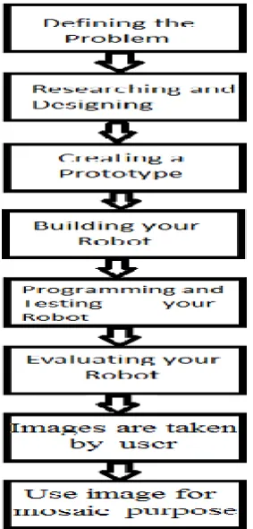
A Process of design a robot-
Define the Problem.
Research and Designing.
Create a Prototype.
Build your Robot.
Programming and Testing Robot.
Evaluate the designing.
Images are taken by user.
Use image for mosaic purpose.
© 2014, IJCSMC All Rights Reserved
605
Fig 1:- Solution methodology for multi sensor robot
In this paper, we use wireless robot which play different roles in different purpose like line follow, obstacle avoidance or follow, light follow or avoidance and react on basis of sound. There are a wireless camera in this robot which are placed on the top of robot’s arm. This camera is used here to take image for further image stitching algorithm.
There are two sided work on these paper one is transmitter side means computer side and another with receiver side means robot side.
Transmitter side works doing by user who offers the instruction to the robot through radio frequency signals by using personal computer. This signal are first encoded by the microcontroller and then transmitted.
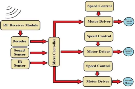
Below fig 2 and fig 3 are shows that the working of RF module.
Fig 2:- Transmitter side block diagram
© 2014, IJCSMC All Rights Reserved
606
Fig 3:- Receiver side block diagram
In the above figure, The RF module operates on radio frequency. The corresponding frequency range varies between 30 kHz & 300 GHz. In this RF module, the digital information is represented as variation in the amplitude of carrier wave. This manner of modulation is known as Amplitude Shift Keying (ASK).
Transmission through RF module is better than IR (infrared) because of many reasons. Firstly, signals through RF can transmit through larger distances making it suitable for long range application. RF signals can travel even when there is an obstacle between transmitter & receiver. Next, RF transmission is much strong and reliable than IR transmission. RF communication uses a specific frequency where as IR signals which are affected by other IR emitting sources.
This RF module be composed of an RF Transmitter and an RFReceiver. The transmitter/receiver (T x/Rx) pair operates at a frequency of 434 MHz. An RF transmitter receives serial data and transmits it wirelessly through RF through its antenna connected at pin4. The transmitted data is received by an RF receiver operating at the same frequency as that of the transmitter.
The RF module is often used along with a pair of encoder/decoder. The encoder is used for encoding parallel data for transmission feed while reception is decoded by a decoder.
Diode (LED)–
Diode is an electronic component which permits the flow of current in one direction. Today diodes are made up of semiconductor materials; therefore they are often called semiconductor diodes or crystal diodes. Diodes are used to rectification and in electrical meters for their protection. Diodes are semiconductor devices made with silicon germanium. There are 4 types of diodes:
• PN Junction Diode.
• Zener diode.
• Light Emitting Diode.
• Photo Diode.
Here during this paper we tend to used only Light Emitting Diode and Photo Diode.
• IR sensor elements works on the principles of emitting IR rays and receiving the reflected ray by a receiver (Photo Diode).
• IR source (LED) is used in forward bias. It emits light when connected in current.
• IR Receiver (Photodiode), often known as Photo Detector is used in reverse bias. Lights fall on the photo diode which creates electron hole pair in the depletion layer which cause flow of current. Current depends upon the light intensity when light incident in the photo diode the current flows in the circuit.
An infrared sensor is an electronic device that emits and/or detects infrared radiation in order to sense some aspect of its surroundings. Infrared sensors can sense the heat or more intensity of light of an object, as well as detect motion. All objects emit some form of thermal heat, usually in the infrared spectrum. These radiations aren’t seeing by the human eyes.
© 2014, IJCSMC All Rights Reserved
607
Fig 4:- Circuit Diagram of IR sensor. Fig 5:- Working of IR sensor.
Through IR sensor we can move left or right wheel of the robot. When IR sensor senses any object, it gives the instruction to micro controller to take the decision of moving the motor on left or right side. This transferring the decisions through IR sensor to motor takes within seconds.
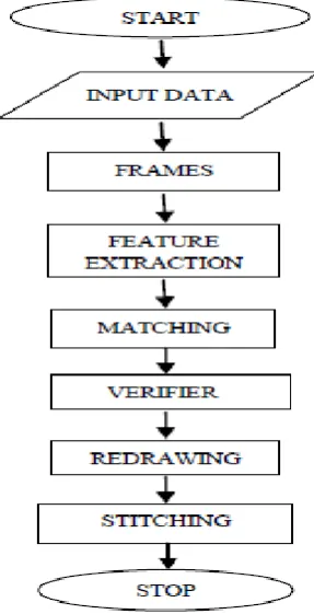
Below fig 6 show that the flow diagram of the image stitching process
Fig 6 :- Block diagram of image stitching process.
© 2014, IJCSMC All Rights Reserved
608
Step4: Compute the common points of grid based of target images and source images.
Step5: Both common points are correlated.
Step6: Find the homography using STITCHER Algorithm. Call STITCHER
Step7: Best matching points are obtained and call MATCHER and VERIFIER
REFERENCES
[1] Bellotto N. and Hu H. February, Multisensor-Based Human Detection and Tracking for Mobile Service Robots. IEEE Transactions on Systems, Man, and Cybernetics, 39(1). ISBN: 1083-4419. 167-181, 2009. [2] Hackett J.K. and Shah M., Multisensor fusion: A Perspective. Trends in Optical Engineering, Center for
Research in Electro, Optics and Laser by National Science Foundation. 99-118, 1993.
[3] Huang Y.J., Chen Y.Z., Kuo C.T., and Yu H.S., Design and Implementation of a Multifunctional Mobile Robot. ICROS-SICE International Joint Conference. ISBN: PR0002/09/0000-3414. 3414-3417, August, 2009.
[4] Kadu R.A, More V.A., Chitte P.P., Rana J.G., and Bendre M.R., Wireless Control & Monitoring of Robotic Arm (SWORDS). International Journal of Computer Technology and Electronics Engineering (IJCTEE). ISSN: 2249-6343. 2(1): 28-38, 2012.
[5] Kam M., Zhu X., and Kalata P., Sensor Fusion for Mobile Navigation. Proceedings of IEEE. ISBN: 0018-9219. 108-119, January, 1997.
[6] Koech H., Konig A., Weigl-Seitz A., Kleinmann K., and Suchy J., Multisensor Contour Following With Vision, Force, and Acceleration Sensors for an Industrial Robot. IEEE Transactions on Instrumentation and Measurement, 62(2). ISBN: 0018-9456. 268-279 , February 2013.
[7] Lin C.Y., Tseng C.K., and Jo P.C., Multi-functional Intelligent Robot DOC-I. IEEE-RAM’06. ISBN: 1-4244-0025-2/06. 1-7, 2006.
Step 3.Find the homography using STITCHER Algorithm. Call STITCHER.
Step 4.Best matching points are obtained and call MATCHER and VERIFIER.
Algorithm4:Image Matching and verification :MATCHER and VERIFIER
Step1: Normalization is used for all the common points of the images after the best common points are detected from grids.
Step2: All other points are changed by scaling and rotation. TRS theory is used then target image is changed.
Step3: Generated image is redrawn through re-paperion of all grids points.
Step4: Final mosaiced image is formed.
Step5: End.
Algorithm 3:Image Stitching: STITCHER
Step1: For stitching purpose, matching of all corners means top left , top right, bottom left, and bottom right of all grids of the source image with reference to target images.
Step2: Correlation method is used.
Step3: Call MATCHER and VERIFIER
© 2014, IJCSMC All Rights Reserved
609
[8] Lin C.Y., Tseng C.K., and Jo P.C., Multi-functional Intelligent Robot DOC-II. IEEE-HUMANOIDS’06. ISBN: 1-4244-0200-X/06. 530-535, 2006.
[9] Luo R.C. and Chang C.C., Multisensor Fusion and Integration: A Review on Approaches and Its Applications in Mechatronics. IEEE Transactions on Industrial Informatics, 8(1). ISBN: 1551-3203. 49-60, February 2012.
[10] Luo R.C. and Su K.L., The Development of a Multisensor Based Intelligent Security Robot. Proceedings of 2005 IEEE International Conference on Mechatronics. ISBN: 0-7803-8998-0105. 970-975, July, 2005. [11] Luo R.C., Lin T.Y., Chen H.C., and Su K.L., Multisensor Based Security Robot System for Intelligent
Building. IEEE Conference on Multisensor Fusion and Integration for Intelligent Systems. ISBN: 1-4244-0567-X/06. 408-413, September, 2006.
[12] Marques C. and Lima P., AvoidingObstacles – Multisensor Navigation for Nonholonomic Robots in Cluttered Environments. IEEE Robotics and Automation Magazine. ISBN: 1070-9932/04. 70-82, September, 2004.
[13] Muhammed M.B., Mohd.Muji S.Z.B., Zakaria S.R., and Mohd. Jenu M.Z.B., MR999-E Wireless Robotic Arm.
[14] Sharma S.M. Multifunctional Autonomic Robotic System (MARS). International Journal of Science and Modern Engineering (IJISME). ISSN: 2319-6386. 1(6): 56-58, 2011.
[15] Bheda D., Joshi M., and Agrawal V. A Study on Feature Extraction Techniques for Image Mosaicing. International Journal of Innovation Research in Computer and Communication Engineering (IJRICCE). ISSN: 2320-9801. 2(3):3432-3437, 2014.
[16] Joshi H. and Sinha K. February, 2013. A Survey on Image Mosaicing Techniques. International Journal of Advanced Research in Computer Engineering and Technology (IJARCET). ISSN: 2278-1323. 2(2):365-369