Scholarship@Western
Scholarship@Western
Electronic Thesis and Dissertation Repository
8-19-2011 12:00 AM
On Developing Novel Energy-Relates Nanostructured Materials by
On Developing Novel Energy-Relates Nanostructured Materials by
Atomic Layer Deposition
Atomic Layer Deposition
Xiangbo Meng
The University of Western Ontario
Supervisor Dr. Sun, Xueliang
The University of Western Ontario
Graduate Program in Mechanical and Materials Engineering
A thesis submitted in partial fulfillment of the requirements for the degree in Doctor of Philosophy
© Xiangbo Meng 2011
Follow this and additional works at: https://ir.lib.uwo.ca/etd
Part of the Nanoscience and Nanotechnology Commons, and the Other Materials Science and Engineering Commons
Recommended Citation Recommended Citation
Meng, Xiangbo, "On Developing Novel Energy-Relates Nanostructured Materials by Atomic Layer Deposition" (2011). Electronic Thesis and Dissertation Repository. 247.
https://ir.lib.uwo.ca/etd/247
This Dissertation/Thesis is brought to you for free and open access by Scholarship@Western. It has been accepted for inclusion in Electronic Thesis and Dissertation Repository by an authorized administrator of
DEPOSITION
(Spine Title: Nanostructured Materials by Atomic Layer Deposition)
(Thesis Format: Integrated-Article)
By
Xiangbo Meng
Graduate Program in Engineering Science Department of Mechanical and Materials Engineering
A thesis submitted in partial fulfillment of the requirements for the degree of
Doctor of Philosophy
The School of Graduate and Postdoctoral Studies The University of Western Ontario
London, Ontario, Canada
THE SCHOOL OF GRADUATE AND POSTDOCTORAL STUDIES
CERTIFICATION OF EXAMINATION
Supervisor Examiners
Dr. Xueliang (Andy) Sun Dr. Sean Barry
Co-Supervisor Dr. Paul Charpentier
Dr. Jun Yang Supervisory Committee
Dr. Jun Yang Dr. Jeffrey T. Wood
The thesis by
Xiangbo Meng
entitled:
On Developing Novel Energy-related Nanostructured Materials by
Atomic Layer Deposition
is accepted in partial fulfillment of the requirements for the degree of
Doctor of Philosophy
Date: August 19, 2011 Dr. Barry Hoffmaster Chair of the Thesis Examination Board
This thesis presents the fabrication of a series of novel nanostructured materials using atomic layer deposition (ALD). In contrast to traditional methods including chemical vapor deposition (CVD), physical vapor deposition (PVD), and solution-based processes, ALD benefits the synthesis processes of nanostructures with many unrivalled advantages such as atomic-scale control, low temperature, excellent uniformity and conformality. Depending on the employed precursors, substrates, and temperatures, the ALD processes exhibited different characteristics. In particular, ALD has capabilities in fine-tuning compositions and structural phases. In return, the synthesis and the resultant nanostructured materials show many novelties.
This thesis covers ALD processes of four different metal oxides including iron oxide, tin oxide, titanium oxide, and lithium titanium oxide. Four different substrates were used in the aforementioned ALD processes, i.e., undoped carbon nanotubes (CNTs), nitrogen-doped CNTs (N-CNTs), porous templates of anodic aluminum oxide (AAO), and graphene nanosheets (GNS). In practice, owing to their distinguished properties and structural characters, the substrates contributed to various novel nanostructures including nanotubes, coaxial core-shell nanotubes, and three-dimensional (3D) architectures. In addition, the surface chemistry of the substrates and their interactions with ALD precursors also were considered.
The ALD process of iron oxide (ALD-Fe2O3) was the first one studied and it was fulfilled
on both undoped CNTs and N-CNTs by using ferrocene and oxygen as precursors. It was found that N-CNTs are better than undoped CNTs for the ALD-Fe2O3, for they provide
reactive sites directly due to their inherent properties. In contrast, undoped CNTs need pretreatment via covalent acid oxidation or non-covalent modification to create reactive sites before the ALD-Fe2O3 could proceed on their surface. This work resulted in
different CNT-Fe2O3 core-shell structures with controlled growth of crystalline α-Fe2O3.
Another metal oxide, tin dioxide (SnO2) was performed using tin chloride (SnCl4) and
water as ALD precursors. It was synthesized into different nanostructures based on
doped nitrogen atoms but the effects of different nitrogen-doping configurations vary with growth temperatures. In comparison, the ALD-SnO2 on AAO and GNS mainly relies
on hydroxyl groups. A common finding from the studies is that growth temperatures influence the resultant SnO2, leading to amorphous, crystalline phase, or the mixtures of
the aforementioned two. In addition, the cyclic nature of ALD contributes to controlled growth of SnO2. Based on the results from the ALD-SnO2 on AAO, it was concluded that
the ALD-SnO2 experience three different growth modes with temperature, i.e.,
layer-by-layer, layer-by-particle, and evolutionary particles. The layers are in amorphous phase while the particles are in crystalline rutile phase. The aforementioned understandings on ALD-SnO2 led to pure SnO2 nanotubes based on AAO, CNT-SnO2 core-shell coaxial
nanotubes, and GNS-based SnO2 3D architectures with controlled growth and structural
phases.
The third metal oxide, titanium dioxide (TiO2) was deposited using titanium isopropoxide
(TTIP) and water as ALD precursors. It was found that the ALD-TiO2 is tunable from
amorphous to crystalline anatase phase with temperature while the resultant deposition is controllable from nanoparticles to nanofilms as well. Based on different substrate, i.e., AAO, acid-pretreated CNTs, and GNS, TiO2 was fabricated with different nanostructures
including nanotubes, core-shell coaxial nanotubes, and 3D architectures. In particular, the resultant nanostructures are distinguished with controlled phases and morphologies of TiO2.
Different from the above binary metal oxides, the last metal oxide, lithium titanium oxide (Li4Ti5O12, LTO) is a ternary compound. The route for ALD-LTO is based on combining
and tuning two sub-ALD systems. One sub-ALD system is for TiO2 using TTIP and
water, and another sub-ALD system is for lithium-containing films using lithium tert-butoxide (LTB) and water as precursors. It was revealed that, through suitably matching the ratios of the two sub-ALD systems and annealing the resultant films, LTO is successfully synthesized on N-CNTs. However, this pioneering work shows a bit rutile TiO2 with LTO, and thus further effort is needed in future work.
ALD systems and provide a series of novel nanostructured materials for various potential applications. In particular, these materials are promising candidate materials for energy-related devices, such lithium-ion batteries, fuel cells, and solar cells.
Keywords: Atomic layer deposition, Nanostructured materials, Metal oxides, Iron oxide, Tin dioxide, Titanium dioxide, Lithium titanium oxide, Anodic aluminum oxide, Carbon nanotubes, Graphene nanosheets, Nanotube arrays, Core-shell coaxial nanotubes, Three-dimensional networks, Renewable clean energy devices, Lithium-ion batteries, Fuel Cells, Solar cells.
1.
Title: Emerging Applications of Atomic Layer Deposition for Lithium-ion Batteries Authors: Xiangbo Meng and Xueliang Sun
This review paper was designed and wrote by Xiangbo Meng under the guidance of Dr. Xueliang Sun. The initial draft and the followed modifications of this manuscript were conducted by Xiangbo Meng under the supervision of Dr. Xueliang Sun. The final version of this manuscript is to be submitted for publishing.
2.
Title: Heterostructural Coaxial Nanotubes of CNT@Fe2O3 via Atomic Layer Deposition:
Effects of Surface Functionalization and Nitrogen-doping
Authors: Xiangbo Meng, Mihnea Ionescu, Mohammad Norouzi Banis, Yu Zhong, Hao Liu, Yong Zhang, Shuhui Sun, Ruying Li, and Xueliang Sun
All the experimental and theoretical work was carried out by Xiangbo Meng under the guidance of Dr. Xueliang Sun. The initial draft and the followed modifications of this manuscript were conducted by Xiangbo Meng under the supervision of Dr. Xueliang Sun. The other coauthors contributed to the formation of the final version with discussion and related characterization. The final version of this manuscript has been published in
Journal of Nanoparticle Research, 2011, 13, 1207-1218.
3.
Title: Three Growth Modes and Mechanisms for Highly Structure-tunable SnO2
Nanotube Arrays of Template-directed Atomic Layer Deposition
Authors: Xiangbo Meng, Yong Zhang, Shuhui Sun, Ruying Li, and Xueliang Sun
All the experimental and theoretical work was carried out by Xiangbo Meng under the guidance of Dr. Xueliang Sun. The initial draft and the followed modifications of this manuscript were conducted by Xiangbo Meng under the supervision of Dr. Xueliang Sun. The other coauthors contributed to the formation of the final version with discussion and related characterization. The final version of this manuscript has been published in
4.
Title: Nitrogen-doped carbon nanotubes coated by atomic layer deposited SnO2 with
controlled morphology and phase
Authors: Xiangbo Meng, Yu Zhong, Yifan Sun, Mohammad Norouzi Banis, Ruying Li, and Xueliang Sun
All the experimental and theoretical work was carried out by Xiangbo Meng under the guidance of Dr. Xueliang Sun. The initial draft and the followed modifications of this manuscript were conducted by Xiangbo Meng under the supervision of Dr. Xueliang Sun. The other coauthors contributed to the formation of the final version with discussion and related characterization. The final version of this manuscript has been published in
Carbon, 2011, 49, 1133-1144.
5.
Title: Non-Aqueous Approach to Synthesize Amorphous/Crystalline Metal Oxide-Graphene Nanosheet Hybrid Composites
Authors: Xiangbo Meng, Dongsheng Geng, Jian Liu, Mohammad Norouzi Banis , Yong Zhang, Ruying Li, and Xueliang Sun
All the experimental and theoretical work was carried out by Xiangbo Meng under the guidance of Dr. Xueliang Sun. The initial draft and the followed modifications of this manuscript were conducted by Xiangbo Meng under the supervision of Dr. Xueliang Sun. The other coauthors contributed to the formation of the final version with discussion and related characterization. The final version of this manuscript has been published in
Journal of Physical Chemistry C, 2010, 114, 18330-18337.
6.
Title: Controllable Atomic Layer Deposition of One-dimensional nanostructured TiO2
Authors: Xiangbo Meng, Mohammad Norouzi Banis, Dongsheng Geng, Yong Zhang, Ruying Li, and Xueliang Sun
All the experimental and theoretical work was carried out by Xiangbo Meng under the
manuscript were conducted by Xiangbo Meng under the supervision of Dr. Xueliang Sun. The other coauthors contributed to the formation of the final version with discussion and related characterization. The final version of this manuscript is to be submitted for publishing.
7.
Title: Controllable Synthesis of Graphene-based Titanium Dioxide Nanocomposites by Atomic Layer Deposition
Authors: Xiangbo Meng, Dongsheng Geng, Jian Liu, Ruying Li, and Xueliang Sun All the experimental and theoretical work was carried out by Xiangbo Meng under the guidance of Dr. Xueliang Sun. The initial draft and the followed modifications of this manuscript were conducted by Xiangbo Meng under the supervision of Dr. Xueliang Sun. The other coauthors contributed to the formation of the final version with discussion and related characterization. The final version of this manuscript has been published in
Nanotechnology, 2011, 22, 165602.
8.
Title: Tunable Atomic Layer Deposition of CNT-based Lithium Titanium Oxide Nanocomposites
Authors: Xiangbo Meng, Jian Liu, Mohammad Norouzi Banis, Jinli Yang, Ruying Li, and Xueliang Sun
All the experimental and theoretical work was carried out by Xiangbo Meng under the guidance of Dr. Xueliang Sun. The initial draft and the followed modifications of this manuscript were conducted by Xiangbo Meng under the supervision of Dr. Xueliang Sun. The other coauthors contributed to the formation of the final version with discussion and related characterization. The final version of this manuscript is to be submitted for publishing.
I dedicate this book to my beloved wife who
shares my dreams and sacrifices for them!
This thesis is the account of my 32-month devoted work in the fields of materials engineering at The University of Western Ontario (UWO), Canada.
Upon this point, I would like to express my deep gratitude first to my supervisor, Dr. Xueliang (Andy) Sun, the Canada Research Chair in Development of Nanomaterials for Clean Energy and the Director of Nanomaterials and Energy Group (NEG), a professor in the Department of Mechanical & Materials Engineering (MME) at UWO. We got to know each other in 2005. At that moment I was studying for my first PhD degree in Chemical & Biochemical Engineering at UWO. Dr. Sun is a basketball fan and the case also goes to me. So, he kindly brought me into a team for fun and offered my family with a driving every time, for we had no vehicles. I did enjoy a lot of time from basketball with Dr. Sun and other fans. Later on, not just basketball, I found we were also having others in common, such as fishing. Thanks to these games, we got lots of joys in remembrance. When the time approached my graduation in 2008, I started to think about my future career and some tiny things commonly called nano interested me. Fortunately, I received a chance to work in Dr. Sun’s group and got to know more about nano and its uses. My fresh touch on nano started with a system named atomic layer deposition. Again, I would like to appreciate Dr. Sun’s trust which granted me this project. Especially, Dr. Sun’s timely guidance helped me deliver the first article and the following ones. In particular, his strong support made my NSERC PDF application a success and a Student Award at the 11th International Conference on Atomic Layer Deposition (2011, Cambridge, MA, USA). Now, when it is approaching the finishing of my PhD in materials engineering, the time in Dr. Sun’s group and his persistent help are for sure the most precious treasures for my future career.
I am also very grateful to Mrs. Ruying Li, Dr. Sun’s wife and a research engineer in the group. Besides teaching me a lot of skills on characterizing nanomaterials, Mrs. Li gave her support in my experiments as well. Furthermore, Mrs. Li provide her warm assistance
contagious personalities.
I want to extend my appreciation to my advisory committee member, Dr. Jun Yang, a professor in MME at UWO for his advice to my studies in every stage. Also, particularly I would like to thank Dr. Yang for his strong support to my application of NSERC PDF. All his help contributed to my fruitful studies in MME. Also, I appreciate his insightful comments on my defense.
I further deeply appreciate Dr. Sean Barry, a professor in the Department of Chemistry at Carleton University and a world-class expert on ALD, for his careful examination on my thesis and for his beneficial discussion and comments as well. I also would like to thank Dr. Paul Charpentier, a professor in the Department of Biochemical and Chemical Engineering at UWO and Dr. Jeffrey Wood, a professor in MME at UWO. As examiners of my defense, they both provided many helpful suggestions to improve my thesis.
My thanks also go to all my group members, the talented researchers with many excellent professional skills. Without their collaboration, my project could not have been done so smoothly. Specially, I would extend my thanks to Mr. Yu Zhong for CNTs, Dr. Dongsheng Geng for GNS, Dr. Yong Zhang for AAO and Raman, Mr. Mohammad Norouzi Banis and Ms. Jinli Yang for XRD, and Mr. Jian Liu for FTIR and CNTs. Also, thanks for helpful discussions from the couple, Dr. Shuihui Sun and Dr. Gaixia Zhang.
I would also like to thank the help from Cambridge Nanotech for their instruction and help on our ALD system. Particularly, my thanks go to Dr. Eric Deguns who provided lots of helpful discussion on ALD. In addition, I appreciate Mr. Fred Pearson at McMaster University, who assisted me with HRTEM observation.
Specially, I owe my parents, Fanxi Meng and Haisu Feng for their understanding and support on my pursuits. Their persistence, kindness, and honesty are always of the greatest worth and have already rooted in my life. I would also like to thank my sisters,
of our parents.
Finally, I am indebted to my dear wife, Aiying Shao for her years’ support and love. Without her tireless dedication to our family, this thesis would not have been delivered. It is my luck to experience the life with her. I would also like to say “thanks” to my lovely daughter, Kexin and my cute son, Keming for their contributions to our family with so much happiness and proud.
Xiangbo Meng
TABLE OF CONTENTS
CERTIFICATE OF EXAMINATION..…...………..ii
ABSTRACT……….………..iii
CO-AUTHORSHIP ………..………..………vi
DEDICATION………ix
ACKNOWLEDGEMENGTS ...………...………..……….x
TABLE OF CONTENTS………...………xiii
LIST OF TABELS………xix
LIST OF FIGURES …………..………...……….xx
LIST OF APPENDICES.…….…………...……….xxix
LIST OF ABBREVIATIONS..………...……….xxx
CHAPTER 1. GENERAL INTRODUCTION……….…….1
1.1 Introduction………2
1.1.1 Atomic layer deposition and its applications………...2
1.1.2 Energy challenges and solutions………3
1.1.3 The opportunities with nanostructured materials…….6
1.2 Objectives………..8
1.3 Thesis Structure………10
1.4 Major Contributions………..……….…..12
References………15
CHAPTER 2. LITERATURE REVIEW………19
2.1 Atomic Layer Deposition ……….…20
2.1.1 A briefing on traditional film deposition techniques.20 2.1.2 Mechanisms..……….………….21
2.2 Emerging Applications of Atomic Layer Deposition for
Lithium-ion Batteries………..………...29
2.2.1 Background………29
2.2.2 ALD on designing novel battery components……32
2.2.3 ALD on surface-modifying battery electrodes……44
2.2.4 Conclusions and outlooks………..59
2.3 Challenges of Atomic Layer Deposition ………....62
2.3.1 Rapid deposition ...……….………...62
2.3.2 Deposition of single and multi-elemental materials..62
2.3.3 Mass production ……….…...62
2.4 Summary………..63
References………64
CHAPTER 3. EXPERIMENTAL APPARATUS AND MATERIALS……….79
3.1 Experimental Setup and Procedures…….…………...………..80
3.1.1 Experimental setup…..……….80
3.1.2 Experimental procedures………..………81
3.2 Materials and Synthesis Strategies…...……….82
3.2.1 Substrates and precursors…..……….82
3.2.2 Strategies for nanostructures………….………84
3.3 Characterization Techniques..……….85
References………86
CHAPTER 4. HETEROSTRUCTURAL COAXIAL NANOTUBES OF CNT@Fe2O3 VIA ATOMIC LAYER DEPOSITION: EFFECTS OF SURFACE FUNCTIONALIZATION AND NITROGEN-DOPING …..….………88
4.1 Introduction……….….90
4.2 Experimental………91
4.2.2 ALD-Fe2O3 processes………....93
4.2.3 Characterization techniques………....94
4.3 Results and Discussion………94
4.3.1 Effects of surface functionalization…..….…………94
4.3.2 Effects of N-doping Results………99
4.4 Conclusions………104
Acknowledgements ………105
References………106
CHAPTER 5. THREE GROWTH MODES AND MECHANISMS FOR HIGHLY STRUCTURE-TUNABLE SnO2 NANOTUBE ARRAYS OF TEMPLATE-DIRECTED ATOMIC LAYER DEPOSITION………..…………...………112
5.1 Introduction………114
5.2 Experimental...………116
5.2.1 Template-directed ALD-SnO2 for tubular arrays…116 5.2.2. Characterization ………..117
5.3 Results and Discussion ……….117
5.3.1 Results……….……….117
5.3.2 Discussion………127
5.4 Conclusions………136
Acknowledgements………136
References………..………138
Supporting Information………142
CHAPTER 6. NITROGEN-DOPED CARBON NANOTUBES COATED BY ATOMIC LAYER DEPOSITED SnO2 WITH CONTROLLED MORPHOLOGY AND PHASE………....………146
6.1 Introduction……….148
6.2 Experimental………150
6.2.2 ALD-SnO2...150
6.2.3 Characterization………...150
6.3 Results and Discussion………151
6.3.1 Results………..151
6.3.2 Discussion………..………..158
6.4 Conclusions………169
Acknowledgements………170
References………171
CHAPTER 7. N O N - A Q U E O U S A P P R O A C H T O S Y N T H E S I Z E AMORPHOUS/CRYSTALLINE METAL OXIDE-GRAPHENE NANOSHEET HYBRID COMPOSITES……….176
7.1 Introduction………....178
7.2 Experimental....………..181
7.2.1 Preparation of GNS………….………...181
7.2.2 ALD-SnO2………..……….183
7.2.3 Characterization………..183
7.3 Results and Discussion….……….184
7.4 Conclusions……….194
Acknowledgements………194
References………..195
Supporting Information………200
CHAPTER 8. CONTROLLABLE ATOMIC LAYER DEPOSITION OF ONE-DIMENSIONAL NANOSTRUCTURED TiO2………...…202
8.1 Introduction………204
8.2 Experimental....………..205
8.2.1 ALD-TiO2………..………..205
8.2.2 Functionalization of substrates………206
8.2.3 Characterization………207
8.3.1 Results………207
8.3.2 Discussion………..216
8.4 Conclusions………..………...217
Acknowledgements………217
References………..………218
Supporting Information………222
CHAPTER 9. CONTROLLABLE SYNTHESIS OF GRAPHENE-BASED TITANIUM DIOXIDE NANOCOMPOSITES BY ATOMIC LAYER DEPOSITION………..…...223
9.1 Introduction………225
9.2 Experimental....………..………227
9.2.1 Preparation of GNS ……..………...227
9.2.2 ALD-TiO2.………..………..………...227
9.2.3 Characterization………..228
9.3 Results and Discussion….……….…228
9.3.1 Results………..….……….……228
9.3.2 Discussion………..238
9.4 Conclusions...……….……243
Acknowledgements………244
References………..………245
Supporting Information………..251
CHAPTER 10. ALTOMIC LAYER DEPOSITION OF LITHIUM TITANIUM OXIDE……….…....257
10.1 Introduction………..………..259
10.2 Experimental....………..…260
10.2.1 Synthesis of N-CNTs…..………...260
10.2.2 ALD-LTO………..………260
10.2.3 Characterization………..261
10.3.1 ALD of lithium-containing compound………262
10.3.2 ALD-LTO………265
10.4 Conclusions...……….……268
Acknowledgements………268
References……..………269
CHAPTER 11. GENERAL DISCUSSION...……..………...272
CHAPTER 12. CONCLUSIONS AND SUGGESTIONS…………....275
12.1 Conclusions………276
12.2 Suggestions………..………278
APPENDICES………...………..………..………...280
CURRICULUM VITAE…………..……….………...286
LIST OF TABLES
…...………..C h a p t e r 2….………..………..
Table I Comparison of deposition properties for PVD, CVD, and ALD 28
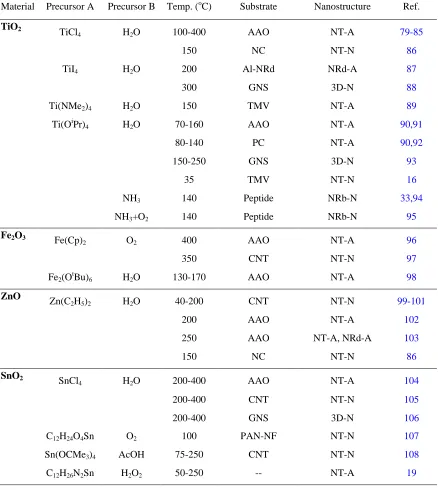
Table II Overview of the materials grown by ALD 28
Table III Nanostructured anode materials by ALD 36
…...………...…….. CHAPTER 2 …….…..……..………..
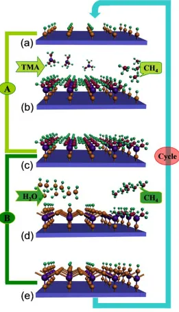
Figure 2.1
A model ALD process by depositing Al2O3using TMA and water as precursors.
(a) the initial substrate covered by hydroxyl groups; (b)TMA molecules reacting with hydroxyl groups, leading to a new intermediate layer; (c) the substrate covered with a new-created intermediate layer; (d) H2O molecules reacting with
the intermediate layer, leading to new hydroxyl groups; (e)the substrate covered again by hydroxyl groups.
22
Figure 2.2
The examples for ALD-fabricated nanostructures. (a) the layered Al2O3-ZnO
nanolaminates on Si substrates; (b) SiO2-coated TiO2composite nanoparticles;
(c) hollow TiO2 nanoribbons; (d) coaxial HfO2 nanotubes; (e) three-layered
discontinued TiO2 3D nanofilms; and (f) complex 3D Al2O3 nanostructures.
27
Figure 2.3
Main ALD strategies for fabricating nanostructured materials. (a) the strategy for nanotube arrays using AAO, exemplified by the fabrication of SnO2
nanotubes; (b) the strategy for nanotubes using CNTs; (c) the strategy for 3D networks of nanotubes based on nanocellulose aerogel; and (d) the strategy for 3D nanostructures based on GNS, exemplified by ALD-TiO2 on GNS.
35
Figure 2.4
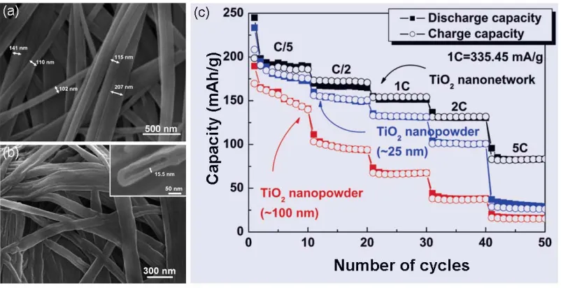
SEM image of (a) the peptide template and (b) the TiO2 network (inset:
magnified image of cross sectional TiO2 hollow nanoribbon). (c) Rate capability
of the TiO2 network, and the 25 nm and 100 nm nanoparticles from C/5 to 5C
for 10 cycles.
37
Figure 2.5
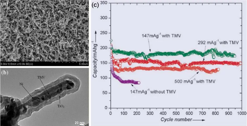
The electrochemical performance of TiO2-(Ni-TMV) nanocomposites as anode
of LIBs. (a) low-magnification SEM image for the TiO2-coated TMV; (b)
high-magnification TEM image for a single composite nanorod where TMV (18 nm), Ni (~20 nm), and TiO2(~ 20 nm). (c) Capacity vs. cycle number for electrodes
with and without TMV.
38
Figure 2.6
ALD-TiO2 coated Al nanorods used as anodes of 3D microbatteries. (a) Al
nanorod arrays; (b) an ALD-TiO2 coated Al nanorod; and (c) normalized
capacity (mAh/cm2 of geometrical surface area) for the 3D microbattery with
TiO2 deposited on an Al nanorod current collector and the 2D electrode with
TiO2 deposited on a flat plate. The galvanostatic cycling current is 0.001 mA.
40
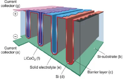
Figure 2.7 A 3D all-solid-state lithium-ion battery. 43
Figure 2.8 indicate regions in which Al was analyzed with EDS. (b)Weight fraction of Al as a function of depth. (c) Electrochemical performance of different anodes at 50
oC.
47
Figure 2.9
Schematic representation of the effects of volume expansion upon (a) bare particles, (b) an ALD coated nano-MoO3 particle, and (c) a particle from an
ALD coated porous anode.
50
Figure 2.10
Charge-discharge cycle performance of electrodes fabricated by the bare LiCoO2
powders and the ALD-Al2O3 coated LiCoO2 powders using 2, 6, and 10 ALD
cycles.
52
Figure 2.11
ALD-Al2O3 modified nano-LiCoO2 particles. (a) 2-cycle ALD-Al2O3 coated
nanoparticles (left), showing the presence of Al by XDS spectrum (right); (b) HR-TME image for a bare nanoparticle; (c) HR-TEM image for a 2-cycle ALD-Al2O3 coated nanoparticle; and (d) cycleability of different cathodes fabricated
by bare bulk-LiCoO2, bare nano-LiCoO2, and 2-cycle ALD-Al2O3 coated
nano-LiCoO2.
54
Figure 2.12
Modification of ALD-Al2O3 on LiMn2O4 cathodes. (a) The bare LiMn2O4
micropowders; (b) 20-cycle ALD-Al2O3 coated LiMn2O4 micropowders; (c)
XPS spectrum from LiMn2O4 cathode coated by 4-cycle Al2O3; and (d) Cycling
performance of (A) bare LiMn2O4 cathode, cathodes coated with (B) 20-cycle
and (C) 10-cycle of ALD-Al2O3. These samples were cycled at a current density
of 240 mA/g over the voltage range of -0.3 – 0.8 V.
57
…...………..…….. CHAPTER 3 ………..………..
Figure 3.1
Experimental setup for atomic layer depositon: A – chamber, B – substrate, C1-3 – precursor cylinders, D1-3 – solenoid valves, E – ALD ebox, F – computer, G – vacuum pump.
80
Figure 3.2 A screen snapshot on the LabVIEW program of the ALD system. 81
……...………..…….. CHAPTER 4 ………..………..
Figure 4.2
200-cycle ALD of iron oxide deposition on the undoped CNTs: without surface pretreatment (a) SEM image and (b) TEM image; treated by 2h nitric acid (c) low magnification and (d)high magnification SEM image; treated by 2 h SDS (e) low magnification and (f) high magnification SEM image; treated by 1 h nitric acid and 1 h SDS in sequence (g) low magnification and (h) high magnification SEM image.
96
Figure 4.3 XRD patterns of the ALD iron oxide on the undoped CNTs treated by nitric acid
and SDS, respectively. 97
Figure 4.4 The N-doped CNTs: (a) low magnification and (b) high magnification SEM
image; (c) HRTEM image. 100
Figure 4.5
The ALD iron oxide on N-doped CNTs illustrated by: SEM images (a) 50 cycles, (c) 70 cycles, and (e) 100 cycles; TEM images (b) 50 cycles; (d) 70
cycles, and (f) 100 cycles. 101
Figure 4.6
Phase and composition characteristics of the ALD iron oxide (70 ALD cycles) on the N-doped CNTs: (a)XRD patterns, (b) TEM image, and (c) HRTEM image.
102
…...………..…….. CHAPTER 5 ….…...………..………..
Figure 5.1
Schematic fabrication of SnO2 nanotubes via template-directed ALD. (a) the
ALD-SnO2 coating on an AAO template, (b) the ALD-coated AAO template, (c)
the mechanically polished AAO template, and (d) the received SnO2 nanotube
array.
117
Figure 5.2 XRD spectra of 1000-cycle ALD-SnO2 at different growth temperatures: (a)
150, (b) 200, (c) 300, and (d) 400 oC. 118
Figure 5.3
The growth characteristics of ALD-SnO2 at 150 oC. (a) EDS spectrum of the
ALD-SnO2 on AAO; top views of AAO after (b) 1000 and (c) 1500 cycles of
ALD-SnO2; the template-removed SnO2 in the forms of (d) clusters and (e)
nanotubes corresponding to 1000 and 1500 cycles, respectively.
119
Figure 5.4
The growth characteristics of ALD-SnO2 at 200 oC. (a) SEM side views of AAO
pores after 500, 1000, and 1500 cycles of ALD-SnO2; (b)the received nanotube
121
away; (c) TEM image for a piece of debris of the deposited SnO2 after
1500-cycle ALD-SnO2 (inset: SAED patterns); (d) high-magnification TEM image for
a local area as indicated in (c); (e)HRTEM image for a local area as indicated in
(c); and (f) HRTEM image for a local area of the beneath layer as indicated in
(e).
Figure 5.5
The growth characteristics of ALD-SnO2 at 300 oC. (a)SEM side views of AAO
pores coated with the ALD-SnO2 of 200, 400, 600, 800, and 1000 cycles (as
marked on the left-bottom corner of each case); (b)SEM images for the received SnO2 nanotubes after 400, 800, and 1000 ALD-cycles (insets: top-views on
ALD-SnO2 of 400 and 800 cycles); (c) the TEM image for the SnO2 nanotubes
of 800 ALD-cycles; (d) the high magnification TEM image for a part of a SnO2
nanotube in (c) (inset: SAED patterns); (e) the HRTEM image for a local area in (d).
123
Figure 5.6
The growth characteristics of ALD-SnO2 at 400 oC. (a)SEM side views of AAO
pores coated with the ALD-SnO2of 400, 600, 800, and 1000 cycles (as marked
on the left-bottom corner of each case); (b) SEM images for the received SnO2
nanotubes after 400, 600, 800, and 1000 ALD-cycles; (c)the TEM image for the SnO2 nanotubes of 600 ALD-cycles; (d)the high magnification TEM image for
one end of a SnO2 nanotube in (c) (inset: SAED patterns); (e) and (f) the
HRTEM images for two local areas in (d).
126
Figure 5.7
Three growth models for ALD-SnO2 nanotube arrays. At a temperature lower
than 200 oC, the ALD-SnO
2 was built up in AAO pores in a mode of (a)
layer-by-layer growth, as schematically shown in (a1-4) with uniform films of increasing thickness; in the range 200-400 oC, the ALD-SnO
2 experienced a
mode of (b) layer-by-particle growth: (b1) amorphous layers prevailed at the initial stage but random nucleation happened with increased films, (b2) crystals grew laterally and radially while new nuclei appeared with increased films, (b3) crystals saturated on the surface and amorphous layers stopped growing, (b4) crystals stopped their lateral growth and competed with each other for their radial growth; at a temperature no less than 400 oC, the ALD-SnO
2 transferred to
a mode of (c) evolutionary particle: (c1) nuclei formed immediately on the substrate surface at the starting of the ALD process, (c2)crystals grew quickly with increased ALD-cycles, (c3) crystals saturated on the substrate surface, (c4) crystals grew predominantly in their radial direction. In (a5), (b5), and (c5), the
133
Figure SI-5.1. and (c) 600 ALD-SnO2 cycles; and SEM images of top-views of AAO pores
after (b) 400, and (d) 600 ALD-SnO2 cycles.
142
Figure SI-5.2
The growth characteristics of ALD-SnO2 at 250 oC. (a)SEM side views of AAO
pores coated with the ALD-SnO2 of 200, 400, 600, 800, and 1000 cycles (as
marked on the left-bottom corner of each case); (b)SEM images for the received SnO2 nanotubes after 600, 800, and 1000 ALD-cycles; (c)the TEM image for
the SnO2 nanotubes of 800 ALD-cycles (inset: SAED patterns); (d) the HRTEM
image for a local area in (c).
143
Figure SI-5.3
Figure SI-5.3 The growth characteristics of ALD-SnO2 at 350 oC. (a) SEM side
views of AAO pores coated with the ALD-SnO2of 200, 400, 600, 800, and 1000
cycles (as marked on the left-bottom corner of each case); (b) SEM images for the received SnO2 nanotubes after 400, 600, 800, and 1000 ALD-cycles; (c) the
arrays of SnO2 nanotubes of 1000 ALD-cycles.
144
Figure SI-5.4 XRD spectra of 200-cycle ALD-SnO2at different growth temperatures: (a) 200,
(b) 250, (c) 300, (d) 350, and (e) 400 oC. 145
…...……….. CHAPTER 6 ………..………..
Figure 6.1
SEM images of N-CNTs with (a) low magnification, and (b)high magnification; (c) XRD spectra of N-CNTs coated with 200-cycle ALD-SnO2 at (▲) 200 oC
and (■) 400 oC; (d) EDS spectra of N-CNTs coated with 200-cycle ALD-SnO 2at
200 oC.
152
Figure 6.2
ALD-SnO2 on N-CNTs at 200 oC. SEM images after (a) 50, (c) 100, and (e) 200
ALD cycles; TEM images after (b) 50, (d) 100, and (f) 200 ALD cycles (insert: SAED patterns); (g and h) HRTEM images of 200-cycle ALD-SnO2.
153
Figure 6.3
ALD-SnO2 on N-CNTs at 400 oC. SEM images after (a) 50, (b) 100, (c) 200, (d)
400 ALD cycles; (e) TEM image of 100-cycle ALD-SnO2 (insert: SAED
patterns); (f and g) HRTEM images of 100-cycle ALD-SnO2.
155
Figure 6.4
ALD-SnO2 on N-CNTs at 300 oC. SEM images after (a) 50, (b) 100, and (c) 200
ALD cycles; (d) TEM image of 200-cycle ALD-SnO2 (insert: SAED patterns); (e and f) HRTEM images of 200-cycle ALD-SnO2.
157
Figure 6.5 Survey scans of XPS spectra for (a) pristine N-CNTs, as well as N-CNTs coated
with 100-cycle ALD-SnO2 at (b) 200 oC and (c) 400 oC.
160
comparison of C ls peaks).
Figure 6.7 High-resolution XPS spectra of N ls peak for (a) pristine N-CNTs as well as for
N-CNTs coated with 100-cycle ALD-SnO2 at (b) 200 oC and (c) 400 oC.
163
Figure 6.8
Schematic diagram of ALD-SnO2 on N-CNTs. (a) The first ALD-SnO2 cycle
functionalized the surface of CNTs: (1) pristine CNTs decorated by N-doping defects, (2) SnCl4 chemically adsorbed on N-CNTs in the first ALD half
reaction induced by N-doping defects, and (3)OH functional groups generated in the second ALD half reaction induced by H2O. (b) The
temperature-dependent ALD-SnO2 on N-CNTs: (1) N-CNTs (blue rings indicating
interlinked nodes) uniformly covered by OH groups at low (L: 200 oC) and
intermediate (I: 300 oC) temperature, but with more OH groups around
interlinked nodes at high (H: 400 oC) temperature; (2) the half-reaction of SnCl 4
dominated by ligand exchange (L), chlorination (H), as well as a competition (I) between the two, respectively; (3) the half-reaction of H2O dominated by ligand
exchange in all the cases (L, I, and H); (4) N-CNTs deposited with tiny amorphous (L), crystalline (H), as well as coexisting amorphous-crystalline nanoparticles (I) after m-cycles (m ≤ 100) of ALD-SnO2; (5) N-CNTs deposited
with coaxial amorphous film (L), coalesced crystalline nanoparticles (H), as well as coaxial amorphous film decorated with crystalline nanoparticles (I) after k-cycles (k > 100) of ALD-SnO2.
168
…...……….. CHAPTER 7 ……….………..………..
Figure 7.1
Schematic illustration of the precise approach to tune the morphology and amorphous-crystalline phases via atomic layer deposition technique (ALD). (a) ALD-SnO2 process employed on graphene nanosheets (GNS) using SnCl4 and
H2O as the two precursors to form amorphous/crystalline SnO2-GNS
nanocomposites; (b) uniformly distributed amorphous SnO2 nanoparticles on
GNS surface and (c) amorphous SnO2 thin film formed on GNS surface by
growing nanoparticles; (d) small crystalline SnO2 nanoparticles uniformly
distributed on GNS surface and (e) large SnO2 nanoparticles uniformly
distributed on GNS surface with higher density.
180
Figure 7.2 Characteristics of GNS: SEM images of (a) low magnification, and (b) high 182
Figure 7.3 200 oC, and (♠) SnO
2-GNS nanocomposites synthesized at 400 oC; (b) EDS
spectra for SnO2-GNS nanocomposites synthesized at 200 oC.
186
Figure 7.4
Amorphous SnO2-GNS nanocomposites: (a) 100 ALD cycles of SnO2; (b) 200
ALD cycles of SnO2; (c) 300 ALD cycles of SnO2; (d) low magnification TEM
image of 300-cycle SnO2; (e) and (f) HRTEM images of 300-cycle SnO2.
188
Figure 7.5
Crystalline SnO2-GNS nanocomposites: (a) 100 ALD cycles of SnO2; (b) 200
ALD cycles of SnO2; (c) 300 ALD cycles of SnO2; (d) low magnification TEM
image of 300-cycle SnO2; (e) and (f) HRTEM images of 300-cycle SnO2.
190
Figure 7.6
Schematic illustration of surface reactions occurred in ALD-SnO2 due to
different growth temperatures: (on left side) amorphization for 200 oC, and (on
the right side) crystallization for 400 oC.
193
Figure SI-7.1
SEM images for natural graphite of (a) lower magnification and (b) higher magnification, as well as graphite oxide of (c) lower magnification and (d) higher magnification.
200
Figure SI-7.2
SEM images for amorphous SnO2-GNS nanocomposites: 100 ALD cycles of
SnO2 with (a) lower magnification and (b)higher magnification of SEM image;
200 ALD cycles of SnO2 with (c) lower magnification and (d) higher
magnification of SEM image.
201
…...……….….….. CHAPTER 8 ………...………..………..
Figure 8.1 (a) XRD patterns induced by ALD-TiO2 at 150 (A) and 250
oC (B). (b) EDS
spectrum of ALD-TiO2 at 150 oC.
208
Figure 8.2
Template-directed ALD-TiO2 at 150 oC. SEM images showing AAO templates
deposited with (a) 500- and (b) 600-cycle ALD-TiO2, and SEM images showing
the received nanotubes arrays after (c) 500- and (d) 600-cycle ALD-TiO2. (e)
TEM image of the received nanotubes (inset: SAED pattern). (f) HR-TEM image of a local area as marked with “f” in (e).
209
Figure 8.3
Template-directed ALD-TiO2 at 250 oC. SEM images showing AAO templates
deposited with (a) 200- (b) 300-, and (c) 500-cycle ALD-TiO2. The received
nanotubes shown by (d) SEM, (e) TEM (inset: SAED pattern), and (f) HR-TEM image (inset: the position for the piece examined by HR-TEM).
211
Figure 8.4 XRD patterns of (A) pristine CNTs, and 300-cycle ALD-TiO2 on CNTs at (B) 212
Figure 8.5 cycles of ALD-TiO2. TEM images of (b) 100, (d) 200, and (f) 300 cycles of
ALD-TiO2. (g) HR-TEM image of 100-cycle ALD-TiO2.
214
Figure 8.6
ALD-TiO2 on CNTs at 250 oC. SEM images of (a) 100, (c) 200, and (e) 300
cycles of ALD-TiO2. TEM images of (b) 100 (inset: HR-TEM image of
nanoparticles), (d) 200, and (f) 300 cycles of ALD-TiO2.
215
Figure SI-8.1 SEM images of (a,b) as-received, (c,d) 1h oxidized, and (e,f) 2h oxidized CNTs 222
…...……….….. CHAPTER 9 ………....………..………..
Figure 9.1 (a) SEM images of GNS; (b) TEM image, and (c) HRTEM image of GNS; (d)
XRD and (e) FTIR spectra of NG, GO, and GNS. 229
Figure 9.2
High-magnification SEM images of (a) pristine GNS, and 300-cycle ALD-TiO2
on GNS at (b) 150 C, (c) 200 C as well as (d) 250 C. Insets are low-magnification SEM images. (e) XRD spectra of 300-cycle ALD-TiO
o o o
2 on GNS at
150 C, 200 C, and 300 C. (f) EDS spectra of 300-cycle ALD-TiOo o o
2 on GNS at
150 C. o
231
Figure 9.3
High-magnification SEM images of ALD-TiO2 on GNS at 150 oC after (a) 50
cycles, (b) 75 cycles (inset for a higher magnification SEM image), (c) 100 cycles, and (d) 200 cycles. (e) TEM and (f) HRTEM image of 75-cycle ALD-TiO2 on GNS at 150 oC.
233
Figure 9.4
High-magnification SEM images of ALD-TiO2 on GNS at 200 oC after (a) 50
cycles, (b) 75 cycles, (c) 100 cycles, and (d) 200 cycles. (e) TEM and (f) HRTEM image of 75-cycle ALD-TiO2 on GNS at 200 oC.
235
Figure 9.5
High-magnification SEM images of ALD-TiO2 on GNS at 250 oC after (a) 50
cycles, (b) 75 cycles, (c) 100 cycles, and (d) 200 cycles. (e) TEM and (f) HRTEM image of 75-cycle ALD-TiO2 on GNS at 250 oC.
237
Figure 9.6 The growth rates (GPC) of ALD-TiO2 with temperatures. 241
Figure SI-9.1 SEM images of (a) NG, (b) GO, and (c) GNS powders. 251
Figure SI-9.2
SEM images for ((a) and (b)) 100-cycle, ((c) and (d)) 200-cycle, and ((e) and (f)) 300-cycle ALD-TiO2 on GNS at 150 oC under a supply of 1.0-s TTIP and 2.0-s
water.
252
Figure SI-9.3 SEM images for ((a) and (b)) 100-cycle, ((c) and (d)) 200-cycle, and ((e) and (f))
300-cycle ALD-TiO2 on GNS at 200 oC under a supply of 1.0-s TTIP and 2.0-s
253
Figure SI-9.4 300-cycle ALD-TiO2 on GNS at 250 oC under a supply of 1.0-s TTIP and 2.0-s
water.
254
Figure SI-9.5
SEM images for ((a) and (b)) 100-cycle, ((c) and (d)) 200-cycle, and ((e) and (f)) 300-cycle ALD-TiO2 on GNS at 150 oC under a supply of 0.5-s TTIP and 1.0-s
water.
255
Figure SI-9.6
SEM images for 200-cycle ALD-TiO2 on GNS at 150 oC under ((a) and (b)) a
supply of 0.8-s TTIP and 1.0-s water as well as ((c) and (d)) a supply of 1.2-s TTIP and 2.5-s water.
256
…...……….….. CHAPTER 10 ……..………..………..
Figure 10.1
XRD patterns induced by the ALD of using Li(OtBu) and water: (a) a sample
coated by a layer of 100-cycle lithium-containing film, (b)a sample coated by a layer of 100-cycle of lithium-containing film and an extra ALD-TiO2 of 100
cycles, (c) a sample coated by a layer of 100-cycle lithium-containing film with 3 h extended heat treatment at 250 oC, (d)the former sample coated with an
extra ALD-TiO2 of 100 cycles, and (e) a sample coated by a layer of 100-cycle
lithium-containing film but annealed at 800 oC for 3 h. (○) is used to identify the
peaks of Li2CO3 and (●) is used to identify the peaks of CHLi2O.H2O.
263
Figure 10.2
ALD-lithium-containing films using Li(OtBu) and water. SEM images for (a) 50
(inset: SEM image after 1 min electron bombardment) and (b) 100 ALD-cycles, and a comparison (c) before and (d) after 1 min electron bombardment on a 100-cycle deposited sample.
265
Figure 10.3
XRD patterns for ALD-LTO of 40 cycles: (a)directly deposited samples as well as annealed samples at (b) 950 and (c) 850 oC for 3 h. (□) is used to identify the
peaks of TiO2 and (■) is used to identify the peaks of Li4Ti5O12.
266
Figure 10.4
SEM images of ALD-LTO after (a) 20, (b) 30, and (c) 40 cycles at 250 oC, and
SEM images of the 40-cycle samples annealed at (d, f) 850, and (e, g) 950 oC.
The insets show the samples with lower magnification.
267
APPENDIX I PERMISSION FROM AMERICAN CHEMICAL SOCIETY (ACS)
FOR PUBLISHED ARTICLE ……….………..281
APPENDIX II P E R M I S S I O N F R O M E L S E V I E R F O R P U B L I S H E D
ARTICLE……….……….………..282
APPENDIX III PERMISSION FROM INSTITUTE OF PHYSICS (IOP) FOR
PUBLISHED ARTICLE..………..……..283
APPENDIX IV PERMISSION FROM ROYAL SOCIETY OF CHEMISTRY
(RSC) FOR PUBLISHED ARTICLE……….………..284
APPENDIX V P E R M I S S I O N F R O M S P R I N G E R F O R P U B L I S H E D
ARTICLE ………285
A
AAO: anodic aluminum oxide AFM: atomic force microscopy ALD: atomic layer deposition
ASS-LIBs : all-solid-state lithium-ion batteries
C
CMOS : complementary metal-oxide-semiconductor CNTs: carbon nanotubes
CVD: chemical vapor deposition
D
DOE: Department of Energy
E
ECs: electrical cars
EDS : energy dispersive X-ray spectroscopy EVs: electrical vehicles
F
FCs: fuel cells
FTIR: Fourier transform infrared spectroscopy
G
GM: General Motor GNS: graphene nanosheets GPC: growth per cycle
H
HEVs: hybrid electrical vehicles
HR-TEM: high resolution transmission electron microscopy
I
ICE: internal combustion engine
L
LIBs: lithium-ion batteries LLT: lithium lanthanum titanate LTB: lithium tert-butoxide
LTO: lithium titanium oxide, Li4Ti5O12
M
MO-GNCs: metal oxide-graphene nanocomposites MWCNTs: multiwalled caron nanotubes
N
NG: natural graphite
N-CNTs: nitrogen-doped carbon nanotubes
P
PEMFCs: proton exchange membrane fuel cells PHEVs: plug-in hybrid electrical vehicles PVD: physical vapor deposition
S
SAED : selected area electron diffraction SCs: solar cells
SEI: solid electrolyte interface
SDS: sodium dodecyl sulfate
SWCNTs: single-walled carbon nanotubes SR: synchronton-radiation
T
TEM: transmission electron microscope TFEL: thin film electroluminescent TMA: trimethylaluminum
TMV: tobacco mosaic virus TTIP: titanium tetra-isopropoxide
X
XAS: X-ray adsorption spectroscopy XPS: X-ray photoelectron spectrometer XRD: X-ray diffraction
CHAPTER 1
1.1Introduction
1.1.1 Atomic layer deposition and its applications
Atomic layer deposition (ALD) is a thin film deposition process first emerged in 1970s,
credited to Suntola and co-workers [1]. Distinguished from other deposition techniques
such as chemical vapor deposition (CVD), physical vapor deposition (PVD), and other
solution-based methods, ALD as a chemical vapor method operates with a unique
mechanism relying on two gas-solid half-reactions to produce an ultimate material [2].
The reactions of ALD feature the characteristics of surface-controlled and
self-terminating nature. In return, ALD performs the deposition of films in a layer-by-layer
mode and it is especially superior in controlling films at the atomic level. As a result,
ALD provides the deposited films with excellent uniformity and unrivalled conformality.
In essence, ALD works with a temperature lower than the decomposition of the used
precursors, typically lower than 400 oC even down to room temperature. In addition, ALD
requires no catalysts and has no needs on solvents. All the aforementioned characteristics
contribute ALD to be a unique but precise deposition technique.
Ascribed to the above-mentioned advantages, ALD is particularly suitable for production
of high-quality thin films. Its initial applications were limited to the growth of II-VI
materials and dielectric thin films for electroluminescent display devices [2], but it was
later widened for the growth of III-V compounds [3]. Besides its successes in the areas of
semiconductors, ALD has been gaining more applications since the beginning of the 21st
century, owing to an increasing recognition on its versatile capabilities. The new widened
applications of ALD are closely related with nanotechnology which offers new
opportunities for many areas with novel components [4,5]. Recent reviews conducted
Knez et al [6], Kim et al [7], and George [8] jointly provide a comprehensive view on the
latest progress of ALD, especially on the fabrication of nanostructured materials. The new
tendencies of ALD in nanotechnology are offering ALD many more opportunities in new
1.1.2 Energy challenges and solutions
A. Energy challenges facing modern society
With ever-growing population and limited resources, the modern and civilized society of
the mankind is facing more pressures than ever before. It is reported that the world
population is growing with an annually increasing rate of more than 0.081 billions a year,
but food and energy as two essential resources are posing challenges for the modern
society [9]. First, the limited food production capability in the earth will not be capable to
produce sufficient food supply for the mankind in the foreseeable future. On the other
hand, the energy supply from all the convincible energy resources (fossil fuel, solar,
geothermal, and nuclear energy resources) will be seriously short in the future even with a
fixed human population of about 10 billion [9]. In particular, each energy source has
some undesirable characteristics [10]: processes of using fossil fuels produce carbon
dioxide and perhaps also other contaminants, such as nitrogen oxides, sulphur oxides and
ash; nuclear plants produce radioactive fission products; hydroelectric plants require dams
and large lakes; solar energy and wind energy require large areas and are limited
geographically; geothermal sources are limited to very few locations. At present, most of
the world’s energy supply comes from fossil and nuclear sources [9,10]. In particular,
about two-thirds of the world’s total electric power is generated from fossil fuels [10],
and electricity generation provides around 40% of humanity’s total energy use [11].
However, world oil production has peaked and the world supply of oil is projected to last
approximately 40-60 years if use continues at current production rates [12]. Natural gas is
considered adequate for about 30 years and coal for less than 100 years [12].
Consequently, mankind has to face the issues of resource limitation. In addition, the
combustion of fossil fuels releases harmful emissions into the air, influencing the
greenhouse effect and the direct health of people, especially in urban areas. Thus, to meet
increasing global demands for energy and to allow for the depletion of fossil fuel supplies
in coming years, alternative “clean” energy sources, which do not depend on fossil fuels
B. Solutions
To meet the challenges posed by the fading fossil fuels and the demands on mitigating
environmental pollution incurred by the combustion of fossil energy, renewable means of
producing and storing electricity are expected to be increasingly important in the future
and could compete with existing technologies based on the strides in condensed-matter
physics and materials technology. In this way, solar cells, fuel cells (FCs), lithium-ion
batteries (LIBs), and supercapacitors are being developing as potential candidates. Of
them, FCs and LIBs stand out for energy conversion and storage, respectively [10].
FCs are electrochemical cells of converting chemical energy to electrical energy,
consisting of two electrodes and a layer of electrolyte. The voltage of the cell depends on
the difference between the two half-cell reactions happened in an anode and a cathode,
respectively. There are many different types of FCs, but they commonly use hydrogen or
methanol as the fuel and produce little pollutants [13]. For example, the most promising
one for electrical cars (ECs) are proton exchange membrane fuel cells (PEMFCs), using
hydrogen as the anode fuel and producing water on the side of cathode as the product.
Direct methanol fuel cells (DMFCs) uses methanol as the anode fuel and produce CO2
and water, particularly suitable for portable electronics such as cell phones, MP3s.
Commonly, they are fed with oxygen in the cathode. Thus, FCs are apparently clean and
environmentally friendly. To boost the half-cell reactions, catalysts are required and
platinum (Pt) is the most efficient and widely used one. However, FCs as an alternative
promising energy conversion technology are by no means new devices and emerged in
the middle of the 19th century [13]. Their development has lagged behind the more
well-known steam engine and internal combustion engine (ICE), mainly due to economic
factors, materials problems, and certain inadequacies in the operation of electrochemical
devices. One of the major factors [13] that influenced the development of FCs over the
last few years is the worldwide concern about the environmental consequences of fossil
fuel use in the day-to-day production of electricity and for the propulsion of vehicles. The
dependence of the industrialized nations on oil became apparent during the oil crises and,
however, is the increasing societal awareness, over the last few decades, concerning
issues of environmental pollution. In 2003, the former US president George W. Bush
announced a US$1.2-billion hydrogen-fuel initiative to develop commercial fuel-cell
vehicles by 2020 [14]. In 2009, US President Barack Obama released a budget for fiscal
year 2010, including more then US$2.3-billion for energy efficiency and renewable
energy [15]. Later in September 2009, nine major car manufacturers (Daimler, Ford,
General Motor (GM), Honda, Hyundai, Kia, Renault, Nissan, and Toyota) signed a joint
statement suggesting that fuel-cell vehicles could hit dealerships by 2015 [14]. The main
advantages of FCs are their higher efficiencies, compared to an ICE, and their lower
emissions. However, fuel cells are still suffering from some critical issues in both cost
and durability. As is well known, the catalyst platinum (Pt) is unacceptable expensive,
accounting for US$60 per gram at the current price [14]. Thus, the reduction of Pt use is
obviously important. GM is expecting to reduce the use of Pt from 80 grams currently to
30 grams in the near future [14]. Another challenge is posed by the degradation of
platinum-based catalyst layer, happened in both the Pt catalyst and carbon support [16].
To reduce cost and improve durability of FCs, some solutions root in: (1) modifying Pt
catalyst; (2) developing non-Pt catalyst; (3) using novel carbon supports; (4) employing
non-carbon supports.
Besides FCs, LIBs represent another technical route of great potential for clean energy.
LIBs are one of the great successes of modern materials electrochemistry, also consisting
of an anode (negative), a cathode (positive), and an electrolyte [17]. This technology has
become a commercial reality through the efforts of the Sony Corporation [18] and others,
and is used widely today in portable computer and telecommunications devices,
especially as these devices get smaller and more efficient [10]. Compared with mature
batteries technologies, such as lead-acid or Ni-Cd, LIBs are still in their infancy, leaving
much hope for improvement [19]. Compared to FCs, according to the US Secretary of
Department of Energy (DOE) Steven Chu, LIBs show more possibility for electrical cars
[18]. To better serve the modern society, LIBs are facing some challenges in further
improvements in both specific energy and power. Typically, carbon materials are used as
or manganese) oxides are employed as positive electodes. However, carbon materials are
approaching their capacity limit. Demand and competition is driving the quest for higher
storage capacity, longer operating times, faster recharging times, and other optimization
of performance [10]. As a consequence, LIBs are experiencing intensive studies mainly
focused on improving specific energy and power [20]. In addition, safety and reliability
are also important for further improvements.
1.1.3. The opportunities with nanostrutured materials
It has been more and more acknowledged that, to tackle the issues with FCs and LIBs
(even solar cells and supercapacitors), nanomaterials are taking very critical roles,
because of the unusual mechanical, electrical and optical properties endowed by
confining the dimensions of such materials and because of the combination of bulk and
surface properties to the overall behavior [21].
In FCs, one of the most important challenges for the ultimate fuel cell commercialization
is the preparation of active, robust and low-cost electrocatalysts [22]. Pt is one main
factor for the cost. One of the present approaches in order to increase the catalyst
dispersion involves the deposition of Pt nanoparticles on carbon black support (Acetylene
Black, Vulcan XC-72, and Ketjen Black [23]) [21], and supported catalysts show higher
activity and stability in comparison to bulk metal catalysts [23]. However, carbon blacks
experienced degradation in a chemical or electrochemical process in FCs [16]. In recent
decades, nanostructured carbon materials were explored as catalyst supports, and carbon
nanotubes (CNTs) are the most well-known nanostructured carbon. The reported studies
have shown that CNTs were superior to carbon blacks as catalyst supports in FCs [16,23].
More recently, since the discovery of graphene in 2004 [24], the interest on this
two-dimensional carbon crystal being supports in FCs is growing. On the other hand, many
studies disclosed that nanostructured transition metal oxides (e.g. SnO2 [25], TiO2 [25,26],
CeO2 [25], V2O5 [27], NbO2/Nb2O5 [28], etc.) are crucial in help Pt or Pd gain higher
oxides is cost-effective for FCs. In addition, nanostructured transition metal oxides were
also investigated as alternative catalysts, such as ZrO2, TiO2, SnO2, Nb2O5, and Co3O4
[29,30]. In particular, metal oxides can be potentially used as supports in place of carbon
materials in FCs with improved durability [31]. Thus, transition metal oxides have
multiple applications in FCs in helping reduce cost and increase durability.
On the side of LIBs, nanomaterials can be used as electrodes, and there are several
potential advantages as well as disadvantages [21]. Favorably, nanomaterials can provide
(i) better accommodation of the strain of lithium insertion/removal, improving cycle life;
(ii) new reactions not possible with bulk materials; (iii) higher electrod/electrolyte contact
area leading to higher charge/discharge rates; (iv) short path lengths for electronic
transport (permitting operation with low electronic conductivity or at higher power); and
(v) short path lengths for lithium ion transport (permitting operation with low lithium ion
conductivity or high power). Unfavorably, they may lead to (i) an increase in undesirable
electrode/electrolyte reactions due to high surface area, leading to self-discharge, poor
cycling and calendar life; (ii) inferior packing of particles leading to lower volumetric
energy densities unless special compaction methods are developed; and (iii) potentially
more complex synthesis. Currently many carbon materials (e.g., natural and synthetic
graphite, petroleum coke, carbon fibers) were generally developed as anodes but
approaching their limits in capacity [13-15]. Thus, in order to increase anode capacities,
carbon alternatives are searched and it was discovered that nanosized materials presented
very promising performances in high capacity, capacity retention, and high recharging
rate [32]. Of them, transition metal oxides cover a wide range of various nanostructured
candidates as promising LIB anodes: SnO2 [33], TiO2 [34], Co3O4 [35], Fe2O3 [36],
MnO2 [37], etc. In parallel, carbon-based nanocomposites were found to be able to
provide more advantages [21]. For example, SnO2 is one of the most promising materials
for next generation of LIBs, presenting very high capacity. However, SnO2 suffers from a
large volume expansion up to 300% in charging-discharging processes [38,39], which
incurs aggregation and thereby badly influences the reversibility. As one solution,
carbon-based SnO2 nanocomposites, for example, SnO2/CNT nanocomposites, were
CNTs [40]. More recent studies, similar to the cases of FCs, are paying a special interest
on graphene and graphene-based metal oxides as anode candidates of LIBs.
Based on the above review, it is apparent that nanostructured metal oxides as well as
carbon-based metal oxide nanocomposites are commonly crucial for the successes of both
FCs and LIBs. Thus, the development on them has practical significance for future energy
conversion and storage technologies.
1.2 Objectives
Renewable clean energy devices are promising to supply alternative energies for our
society. However, FCs and LIBs have urgent needs on advanced nanostructured materials
in order to improve their performance. On the other hand, ALD has the capabilities to
synthesize novel nanomaterials with many advantages over its counterparts such as CVD,
PVD, and solution-based methods. Due to its late emergence for nanotechnology, there is
still a large area for ALD to explore.
In this context, the author devoted to study ALD processes with different precursors on
various substrates in order to prepare novel nanostructured materials with controlled
manners. The efforts were mainly focused on synthesizing nanostructures of several
popular metal oxides including Fe2O3, SnO2, TiO2, and Li4Ti5O12. Determined by the
employed substrates, the aforementioned metal oxides were synthesized into nanotubes,
core-shell structured nanocomposites, or graphene-based 3D nanocomposites. In
particular, the author elucidated the influences of ALD parameters on the fabrication of
the listed metal oxides. In general, ALD is subject to the influences from three key
parameters, i.e., precursors, substrates, and temperatures. As a consequence, the thesis not
only succeeded in the synthesis of the above-mentioned metal oxides with novel
nanostructures but also contribute to the understanding of the growth characteristics of
various ALD processes. In addition, the synthesized nanostructured metal oxides are
(1). To synthesize different nanostructures with different substrates. ALD
surface-controlled nature determines that the resultant nanostructures rely on the characteristics of
substrates. In this study, four kinds of substrates were employed, including porous anodic
aluminum oxide (AAO) templates, undoped carbon nanotubes (CNTs), nitrogen-doped
CNTs (N-CNTs), and graphene nanosheets (GNS). In return, nanotubes, CNT-based
core-shell nanostructures, and GNS-based 3D architectures were developed with different
ALD processes of metal oxides.
(2) To study the growth characteristics of various ALD processes based on different
substrates. Besides their dominance on the ultimate nanostructures, substrates are among
the critical parameters influencing ALD growth characteristics. The influences may be
incurred by the difference on the density of reactive sites between different substrates, or
by their inherent properties such as structures.
(3). To investigate the growth characteristics of various ALD processes with temperatures.
Temperatures are another key factor. Previous studies disclosed that ALD-deposited thin
films might experience a phase-transformation with increased temperatures. Furthermore,
increasing temperatures may also change the surface conditions of substrates, leading to
some change on the growth characteristics.
(4). To investigate the morphological evolution of the deposited materials with increased
ALD-cycles. A distinguishing characteristic of ALD is its deposition precision at the
atomic level. Through controlling ALD cycles, precise control on the morphologies and
thereby on the deposited materials can be designed in purpose.
(5). To gain understandings on underlying mechanisms of various ALD processes. The
general mechanism for various ALD processes is quite straightforward. However,
different precursors are likely to induce different growth characteristics, for they may
induce different surface reactions. Thus, it is essential to explore the underlying
(6). To explore ALD as a technique to tune the composition of complicated compounds.
ALD has widely successes for binary metal oxides or other binary compounds, but
ternary or more complicated compounds often take important roles in many areas. For
example, Li4Ti5O12 is a particularly important material as LIB anode and offers many
advantages. Thus, it is of great importance to develop ternary or more complicated
compound via ALD.
1.3 Thesis structure
This thesis consists of twelve chapters and fulfills the requirements on
“Integrated-Article” form as outlined in the Thesis Regulation Guide by the School of Graduate and
Postdoctoral Studies (SGPS) of The University of Western Ontario. It is built up with the
following arrangement.
Chapter 1: generally introduces the background of ALD and its potential applications. In
this section, the capabilities of ALD for nanostructured materials are highlighted in
energy-related devices, for energy needs represent our most urgent challenges in our
society. Besides some general strategies of ALD for nanostructures, the research
objectives, the thesis structures, and the major contributions from this study are clearly
stated.
Chapter 2: presents a clearer picture of ALD and its characteristics with more detained
information. To highlight the superiority of ALD in energy-related devices, a thorough
review on emerging applications of ALD in LIBs is conducted. In the meantime, the
challenges facing ALD are also summarized.
Chapter 3: outlines the experimental setup, apparatus, materials, and conditions in the

![Table II. Overview of the materials grown by ALD [8].](https://thumb-us.123doks.com/thumbv2/123dok_us/7759688.1273456/61.612.118.552.391.623/table-ii-overview-materials-grown-ald.webp)