1121 P.Raju & SK.Khamuruddin
Stand-Alone Single-Phase Power Generation Employing a
Three-Phase Isolated Asynchronous Generator
Abstract—This paper deals with a stand-alone single-phase power generation using a three-phase isolated asynchronous generator (IAG) coupled with a wind turbine or a pico-hydro turbine. The proposed voltage and frequency controller (VFC) for a stand-alone single-phase power generation is used as a phase balancer for a three-phase IAG, a load leveler, and an active filter. The VFC is realized using a three-leg voltage-source converter and a battery energy storage system. The VFC ensures optimum utilization of a three-phase IAG for feeding a variety of single-phase loads, improves conversion efficiency, and reduces noise and vibration in the IAG. The rating considerations of an IAG and VFCs are also discussed for a single-phase power generation. The performance of an IAG system is demonstrated under steady-state and dynamic conditions of feeding single-phase linear and nonlinear loads. Simulated results are validated with test results on a developed system.
Index Terms—Isolated asynchronous generator (IAG), pico hydro generation, power quality, single-phase power generation, voltage-source converter (VSC), wind energy.
I. INTRODUCTION
A
single-phase power generation and its distribution are preferred with such small-scale stand-alone WECSs to reduce capital investment, maintenance, and improved protection. However, power generation using a single-phase IAG is not economical due to higher frame size and poor conversion efficiency. Three-single-phase IAGs with a standard frame size have been proved to be better alternatives than single-phase IAGs [6]–[18]. However, three-phase IAG feeding single-three-phase loads require three-phase balancing. Bhattacharya and Woodward [6] examined the behavior of three-phase IAGs under single phase loads using the symmetrical component theory. They also proposed an unbalanced excitation scheme to feed single phase loads and methods to determine the derating factor. Smith [7] proposed a phase-splitting method using two capacitors for a three-phase IAG to feed single-phase loads. Fukami et al. [9] analyzed a novel connection for single-phase balancing of three-single-phase IAG feeding single-phase loads using series and parallel combinations of capacitors across generator terminals and loads. In [12], the authors used the Smith connection for a three-phase IAG for self-excitation and phase balancing. It has been reported that for constant speed operation of an IAG, the value of excitation capacitors depends on the amount and nature of loads for perfect phase balancing. Murthy et al. [14] reported the operation of three-phase IAG feeding single-phase loads, and only two excitation capacitors were used for phase balancing. It was shown that only 86.2% of rated capacity of a three-phase IAG can be delivered to single-phase loads. Chan and Lai [16] reported the use of two capacitances and a current injection transformer for a single-phase power generation using a three-phase IAG. Kumaresan [17] analyzed the performance of three-phase IAG feeding single-phase ac and dc loads using a genetic algorithm. It was shown that the excitation capacitance requirement changes for single-phase loading, and the power output from an IAG was found to be much lower than its rated capacity. In [18], the authors determined an optimum value of an excitation capacitor for getting the maximum single phase power output from a three-phase IAG under different loads. Most of these reported publications have been based on assumptions that the input power is constant, and for a specified power output of IAG and constant loads, optimized excitation capacitors may be used. Even with these optimized excitation capacitances, the rating of a three-phase IAG has not been fully utilized, and voltage and frequency regulation are observed as major challenges with prime movers such as a wind turbine with change in input power and consumer loads. Moreover, none of these attempts is able to achieve balanced operation of a IAG under single-phase loads.This paper deals with single-phase power generation using a three-phase IAG with its balanced operation. A three-leg voltage-source converter (VSC) and a battery energy storage system (BESS) are used as a voltage and frequency controller (VFC). This VFC also performs the functions of a phase balancer, a load leveler, and an active filter. These features of the VFC have provided full utilization and balanced operation of a three-phase IAG with smooth control and quiet operation for the single-phase power generation.
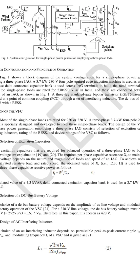
1122 P.Raju & SK.Khamuruddin Fig. 1. System configuration for single-phase power generation employing a three-phase IAG.
II. SYSTEM CONFIGURATION AND PRINCIPLE OF OPERATION
Fig. 1 shows a block diagram of the system configuration for a single-phase power generation employing a three-phase IAG. A 3.7-kW 230-V four-pole squirrel cage induction machine is used as an IAG. A three-phase delta-connected capacitor bank is used across IAG terminals to build the rated terminal voltage. Most of the single-phase loads are rated for 230/220 V ac in India, and these are connected between two terminals of an IAG, as shown in Fig. 1. A three-leg insulated-gate bipolar transistor (IGBT)-based VSC is connected at a point of common coupling (PCC) through a set of interfacing inductors. The dc bus of a VSC is supported with a BESS.
III. DESIGN OF THE VFC
Most of the single-phase loads are rated for 230 or 220 V. A three-phase 3.7-kW four-pole 230-V 50-Hz IAG is specially designed and developed to feed these single-phase loads. The design of the VFC for a single-phase power generation employing a three-phase IAG consists of selection of excitation capacitors, interfacing inductors, rating of the BESS, and device ratings of the VSC as follows.
A. Selection of Excitation Capacitors
The excitation capacitors that are required for balanced operation of a three-phase IAG to build rated terminal voltage are explained in [19] and [20]. The required per-phase capacitive reactance Xc to maintain rated
terminal voltage depends on the nature and magnitude of loads and speed of an IAG. To achieve rated IAG voltage at rated resistive load and rated speed, the obtained value of Xc (i.e., 12.30 Ω) is used to find the
required three-phase capacitive reactive power as follows:
The calculated value of a 4.3-kVAR delta-connected excitation capacitor bank is used for a 3.7-kW four-pole 50-Hz IAG.
B. Selection of a DC-Bus Battery Voltage
The choice of a dc-bus battery voltage depends on the amplitude of ac line voltage and modulation factor for satisfactory operation of the VSC [21]. For a 230-V line voltage, the dc bus battery voltage must be greater than 376 V (= 2√2VL/√3 =1.63 * VL). Therefore, in this paper, it is chosen as 420 V.
C. Design of AC Interfacing Inductors
The choice of an ac interfacing inductor depends on permissible peak-to-peak current ripple ipp, dc bus
1123 P.Raju & SK.Khamuruddin where m is the modulation index, a is the overloading factor, fs is the switching frequency of the VSC, and ipp is
the peakto- peak VSC ripple current.
Considering a modulation index m = 1 under an extreme case, selected dc bus battery voltage Vdc =
420 V, a = 1.2, and fs = 10 kHz. The peak-to-peak VSC ripple current ipp is 10% of the VSC current, and the
value of Li is obtained as 4.2mH. A round off value of 4mH is selected, which is close to the designed value.
D. Selection of Rating of the VSC
The selection of rating of IGBTs used for the VSC is based under an extreme case when the maximum allowable load is connected at the IAG bus and wind speeds and generated power are at minimum. Under such conditions, excitation capacitor reactive power is available to compensate the load reactive power demand, and it relives the VSC to compensate for load reactive power. Considering a 3.7-kW single-phase load on an IAG bus, the load current IL is given as
Therefore, IGBTs of 16-A current rating are required for the VSC. The device voltage rating depends on the maximum dc bus battery voltage. Therefore, considering the safety factor and commercial availability of a device, a set of 600-V 25-A IGBTs is selected for a VSC.
E. Selection of Rating of the BESS
The capacity of a BESS depends on the wind speed profile, the diversity of consumer loads, the loss of load expectation, and the expected reliability of the WECS. Higher capacity
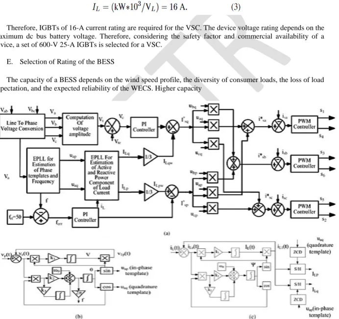
Fig. 2. (a) Proposed control scheme of the VFC for a single-phase power generation employing a three-phase IAG-based stand-alone WECS. (b) EPLL for estimation of frequency and phase voltage templates. (c) EPLL for estimation of the amplitude of active and reactive power components of the load current.
of a BESS allows better contingency handling and improves reliability; however, at the same time, it increases the capital investment and required shelf space. In this paper, a 2.8-kWh BESS is used depending on the availability for the experimental validation of the proposed VFC. For the nominal BESS voltage of 420 V, 35 cells of 12 V, 7 Ah are connected in series. For the simulation model, BESS parameters are obtained as follows.
1124 P.Raju & SK.Khamuruddin For the fully charged and discharged cell voltages of 13.5 and 10.5 V, maximum and minimum dc bus battery voltages Vdcmax and Vdcmin are obtained as 472.5 and 367.5 V, respectively. For a Thevenin’s equivalent
circuit of the BESS, as shown in Fig. 1, the capacity of a battery is defined using a capacitance Cb as
The obtained Cb of 229 F is used in the simulation model. The internal loss resistance per cell is 20mΩ,
and its 3% of capacity declined in a month, as obtained from the data sheet of used cell in the prototype development. There are 35 cells connected in series, and therefore, based on the specification of the cell, the internal resistance Rin of the battery model is considered as 0.98 Ω. The self-discharge resistance considered for
the simulation model based on battery specifications is 1.6MΩ. IV. CONTROL STRATEGY
Fig. 2(a) shows the control strategy of a VFC that also performs as a phase balancer, a load leveler, and an active filter for an IAG-based stand-alone WECS. It is realized using an enhanced phase-locked loop (EPLL) [22]. The control algorithm is used to estimate the reference source currents to control switching of a VSC of the VFC. EPLL modules are used to estimate in-phase and quadrature unit templates of phase voltages and frequency of an IAG. The active and reactive power components of the load current are estimated using an EPLL module, a set of zero-crossing detectors, and sample and-hold circuits. The principle of active filtering is based on injecting equal and out-of-phase harmonics currents present in the loads at the PCC. The proposed control strategy implements active filtering by controlling a three-leg VSC to shape three phase IAG currents that are balanced and sinusoidal in nature. Basic equations that are used in realizing the control algorithm are described as follows.
A. Phase Voltage Transformation
Line voltages vab and vbc are sensed, and phase voltages va, vb, and vc are obtained using the following
transformation matrix [23]:
B. Estimation of the Amplitude of Active and Reactive Power Components of the Load Current
Fig. 2(c) shows an EPLL module that is used for the computation of active and reactive power components of the load current [24]. The fundamental component of load current iL1(t) is in phase with an input signal iL(t);
however, it travels with a certain phase angle with a reference in-phase template uap. Therefore, to extract the
amplitude of an active power component of fundamental load current iL1 in phase with a respective supply
voltage, a zero-crossing detector ZCD1 is used with uaq (quadrature template), which is leading 900 from uap.
Therefore, ZCD1 provides a trigger pulse at the peak of uap. A sample-and-hold circuit SHC1 is used with iL1(t)
as an input signal and ZCD1 output as the trigger pulse. The output of this SHC1 is an amplitude of the active
power component of iL(t). To achieve phase balancing of IAG currents, the active power component of the load
current must be equally shared among all phases of an IAG. Therefore, the weighted average amplitude of the active power component of the load current is obtained after multiplying by a gain of 1/3.
Similarly, to extract the reactive power component of load current iL1(t), a zero crossing detector ZCD2 is
used with the uap in-phase template, which is lagging 900 with the uaq quadrature template. A trigger pulse is
obtained at the peak of uap. Another sample-and-hold circuit SHC2 is used with iL(t) as an input and ZCD2 output
as a trigger pulse. The output of this SHC2 is an amplitude of the reactive power component of iL(t). In this
EPLL, values of k1, k2, and k3 are used as 25, 5, and 5, respectively. To achieve phase balancing of IAG
currents, the reactive power component of the load current must be equally shared in all phases of an IAG. Therefore, the weighted average amplitude of the reactive power component of the load current is obtained after multiplying by a gain of 1/3.
1125 P.Raju & SK.Khamuruddin C. Estimation of Reference Source Currents
The IAG frequency is a function of its speed. For a constant frequency operation, the IAG speed must remain constant even when there is a change in the wind input power or a change in the active power of loads. To achieve this, active power generation is required to be controlled as there is a change in the wind input power. For a constant frequency operation of an IAG, an active power component of reference source currents is obtained using a frequency proportional–integral (PI) controller and the weighted average amplitude of the active power component of the load current as follows.
The active power component of reference source currents is obtained using the weighted average amplitude of the active power component of the load current and an output of a frequency PI controller as follows.
The frequency error is defined as
where frf is the reference WECS frequency (50 Hz in this case), and f is an estimated frequency of phase
voltages of a WECS. The instantaneous value of f is estimated using the EPLL, as shown in Fig. 2(b). At the nth sampling instant, an output of a frequency PI controller is
The amplitude of the active power component of reference source currents is
where ILpw = ILp/3.
For the constant terminal voltage at the PCC, reactive power control is required under change in wind speeds and consumer loads. A fixed excitation capacitor bank is used at IAG terminals to supply rated power under rated wind speed. However, during change in input wind speeds and consumer loads, the reactive power demand of the system also varies. To control the voltage, the reference reactive power component of source currents is obtained using a voltage PI controller and the reactive power component of the load currents as follows.
The reactive power component of reference source currents is obtained using the weighted average reactive power component of load currents and the output of the voltage PI controller as follows.
The ac voltage error at the nth sampling instant is
where Vtr(n) is the amplitude of the reference ac terminal phase voltage, and Vt(n) is the amplitude of the sensed
three-phase ac voltage at the PCC, which is computed as
The output of a voltage PI controller for regulating a constant ac terminal voltage at the nth sampling instant is
where kpv and kiv are the proportional and integral gain constants of a PI controller, respectively. Ve(n) and Ve(n
− 1) are voltage errors at the nth and (n − 1)th sampling instants, and Ivq(n) and Ivq(t − 1) are outputs of a voltage
PI regulator at the nth and (n − 1)th instants.
The amplitude of the reactive power component of the reference source current is given as
1126 P.Raju & SK.Khamuruddin Fig. 3. Performance of the VFC at fixed linear loads under a fall in wind speed.
To estimate the reference source currents, phase templates for other two phases are also required. These templates are obtained using the EPLL block, as shown in Fig. 2(b). Three phase reference source currents are estimated using (8) and (12) and in-phase and quadrature templates as follows:
These three-phase reference source currents (i*sa, i*sb, and i*sc) are compared with sensed source
currents (isa, isb, and isc). These current errors are fed as inputs to a set of PI current controllers to generate
three-phase control signals. These control signals are fed as inputs to pulse width-modulation (PWM) controllers to generate switching pulses for IGBTs of the VSC of the VFC. The VFC controls three-phase source currents. It is therefore justified to have three-phase IAG currents that are balanced and sinusoidal even when single-phase loads are present at the load bus. Furthermore, single-phase active and reactive power components of load currents are also uniformly distributed on each phase, as discussed above. Moreover, because of control of three-phase source currents using the VSC of the VFC, harmonics present in the load currents are also indirectly compensated
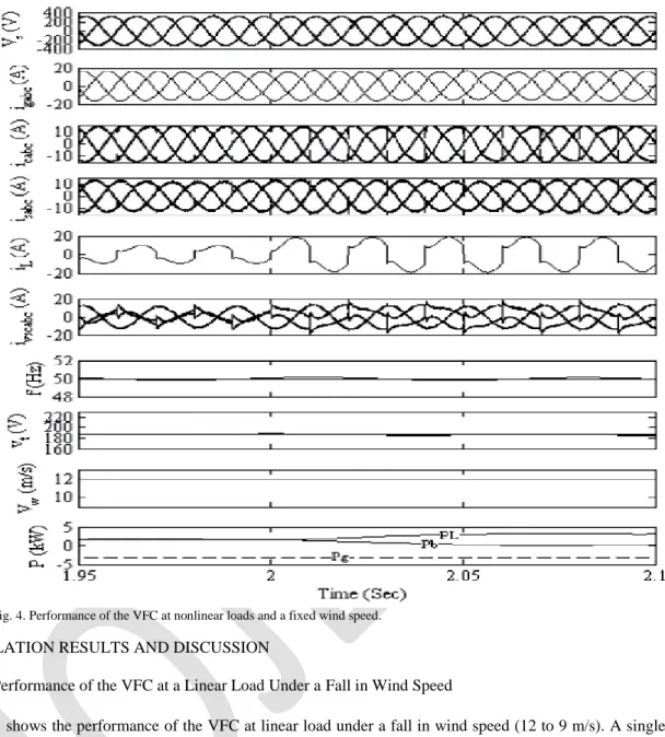
1127 P.Raju & SK.Khamuruddin Fig. 4. Performance of the VFC at nonlinear loads and a fixed wind speed.
V. SIMULATION RESULTS AND DISCUSSION
A. Performance of the VFC at a Linear Load Under a Fall in Wind Speed
Fig. 3 shows the performance of the VFC at linear load under a fall in wind speed (12 to 9 m/s). A single-phase 3.7-kW unity power factor load is connected between terminals “a” and “b.” Until 1.5 s, the wind speed is 12 m/s, and the IAG is developing a power of 3.4 kW. The battery is discharging to feed deficit load power. At 1.5 s, the wind speed falls to 9 m/s, and there is a reduction in generated power, and the battery is supplying the deficit power. It is observed that three-phase generator currents igabc, capacitor currents icabc, and source currents
isabc are balanced even when the single-phase consumer load is connected at the load bus. The VFC is
performing the functions of a phase balancer and a load leveler under a fall in wind speed. The terminal voltage and frequency are maintained constant even under change in the wind speed.
B. Performance of the VFC at a Nonlinear Load
Fig. 4 shows the performance of the VFC delivering single phase nonlinear load at a fixed wind speed of 12 m/s. A single phase diode rectifier feeding resistive-inductive load is used as a nonlinear load. The wind speed is kept at 12 m/s. Until 2 s, a single-phase load is drawing 1.5 kW, and due to higher generation, a battery is absorbing surplus generated power, i.e., 1.9 kW. At 2 s, the consumer load demand increases up to 3.4 kW, and generated power meets the load power demand. The battery experiences floating state at this time. It is observed that the VFC performs the functions of an active filter, a load leveler, and a phase balancer under a single-phase nonlinear load.
1128 P.Raju & SK.Khamuruddin VI Simulation Model and Results
Fig.5.Simulation model for proposed circuit
Fig.6. Simulation results for variable wind speed- Source voltage(Vsabc), grid current(Igabc), controller current(Icabc), Source current(Isabc), Load current(ILabc)
Fig.7. Simulation results for variable wind speed and Linear load-Inverter current(Iabc_inv), Frequency(f), Terminal voltage(Vt) and Wind speed(Vw)
Discrete, Ts = 5e-005 s. powergui A B C a b c VabcA B C a b c A B C a b c A B C a b c A B C Scopes Product Gate Ica Icb Icc Inverter Vw f Iabcl Vs Gate From Vabc(pu) Freq wt Sin_Cos i + -Controller 1515 Tm m A B C <Rotor speed (wm)>
1129 P.Raju & SK.Khamuruddin Fig.8. Simulation results for variable wind speed and Non-Linear load- Source voltage(Vsabc), grid current(Igabc), controller current(Icabc), Source current(Isabc), Load current(ILabc)
Fig.9. Simulation results for variable wind speed and Non-Linear load-Inverter current(Iabc_inv), Frequency(f),
Terminal voltage(Vt) and Wind speed(Vw)
VII. CONCLUSION
A single-phase power generation employing a three-phase IAG has been proposed with a VFC. The VFC has been implemented using a three-leg VSC with a BESS at its dc bus. It has been demonstrated that the developed VFC for a standalone single-phase power generation using a three-phase IAG have provided better utilization of the generator in terms of generated power and quiet operation. It has been also devised as a comprehensive solution for voltage and frequency control, a phase balancer, a load leveler, and an active filter for an IAG based generating system driven through prime movers such as a pico-hydro or a wind turbine. APPENDIX
A) IAG Data:
3.7 kW, 230 V, 14.5 A, 50 Hz, Y-connected, four-pole Rs = 0.39 Ω, Rr = 0.4791 Ω, Lls = 0.00201 H
1130 P.Raju & SK.Khamuruddin Llr = 0.002514 H, Lm = 0.0766 H.
B) Prime-Mover Data:
3.7 kW, 415 V, 7 A, Δ-connected, four-pole, 1430 r/min induction motor driven by ABB make
ac drive ACS550-01-015A. C) VFC Parameters: VSC =25 kVA, Lf = 4mH, Rf = 0.01 Ω, Kpv = 0.3 Kiv =0.02, Kpf = 1, Kif = 0.05. D) Battery Rack: Vdc = 420 V, 2.8 kWh, 35 units of 12 V 7 Ah connected in series Vdcmax = 472.5 V, Vdcmin = 367.5 V, Cdc = 229 F. REFERENCES
[1] M. G. Simoes and F. A. Farret, Renewable Energy Systems. Boca Raton, FL: CRC Press, 2004.
[2] M. Kaltschmitt, W. Streicher, and A. Wiese, Renewable Energy, Technology, Economics, Environment. Berlin, Germany: Springer-Verlag, 2007.
[3] V. Quaschning and H. Jourdan, Renewable Energy and Climate Change. Hoboken, NJ: Wiley, 2010.
[4] E. W. Fuchs and M. A. H. Masoum, Power Conversion of Renewable Energy Systems. New York: Springer-Verlag, 2011. [5] S. N. Bhadra, D. Kastha, and S. Banerjee, Wind Electrical Systems. New Delhi, India: Oxford Univ. Press, 2004.
[6] J. L. Bhattacharya and J. L. Woodward, “Excitation balancing of a selfexcited induction generator for maximum power output,” Proc. Inst. Elect.Eng.—Gen., Trans. Distrib., vol. 135, no. 2, pp. 88–97, Mar. 1988.
[7] O. J. M. Smith, “Three-phase induction generator for single-phase line,” IEEE Trans. Energy Convers., vol. EC-2, no. 3, pp. 382–387, Sep. 1987.
[8] T. F. Chan, “Performance analysis of a three-phase induction generator connected to a single-phase power system,” IEEE Trans. Energy Convers., vol. 13, no. 3, pp. 205–213, Sep. 1998.
[9] T. Fukami, Y. Kaburaki, S. Kawahara, and T. Miyamoto, “Performance analysis of a self-regulated self-excited single-phase induction generator using a three-phase machine,” IEEE Trans. Energy Convers., vol. 14, no. 3, pp. 622–627, Sep. 1999.
[10] T. F. Chan and L. L. Loi, “A novel single-phase self-regulated self-excited induction generator using a three-phase machine,” IEEE Trans. EnergyConvers., vol. 16, no. 2, pp. 204–208, Jun. 2001.
[11] T. F. Chan and L. L. Loi, “Steady-state analysis and performance of a stand-alone three-phase induction generator with asymmetrically connected load impedances and excitation capacitances,” IEEE Trans. EnergyConvers., vol. 16, no. 4, pp. 327–333, Dec. 2001.
[12] T. F. Chan and L. L. Lai, “Single-phase operation of a three-phase induction generator with the Smith connection,” IEEE Trans. Energy Convers., vol. 17, no. 1, pp. 47–54, Mar. 2002.
[13] T. F. Chan and L. L. Loi, “Capacitance requirements of a three-phase induction generator self-excited with a single capacitance and supplying a single-phase load,” IEEE Trans. Energy Convers., vol. 17, no. 1, pp. 90– 94, Mar. 2002.
[14] S. S. Murthy, B. Singh, S. Gupta, and B. M. Gulati, “General steady-state analysis of three-phase self-excited induction generator feeding threephase unbalanced load/single-phase load for stand-alone applications,” Proc. Inst. Elect. Eng.—Gen., Transmiss. Distrib., vol. 150, no. 1, pp. 49– 55, Jan. 2003.
[15] T. F. Chan and L. L. Lai, “A novel excitation scheme for a stand-alone three-phase induction generator supplying single-phase loads,”
IEEETrans. Energy Convers., vol. 19, no. 1, pp. 136–143, Mar. 2004.
AUTHORS
Mr.P.Raju pursuing his M.Tech in Control System at Aurora’s Research & Technological Institute and B.Tech in Electrical & Electronics Engineering. His research interest includes Power Quality, and Renewable Energy Sources.
(E-mail:[email protected])
Mr. Shaik Khamuruddin is with the department of Electrical and Electronics Engineering working as Assoc.Prof & Head at Aurora’s Research and Technological Institute, Warangal, Telengana State. India. His research interest includes Power Electronics and Drives, PLLs, Power Quality, Distributed Generation and Renewable Energy Sources.