Design, Construction, and Application
of a Generic Visual Language
Generation Environment
Kang Zhang,
Senior Member,
IEEE, Da-Qian Zhang, and Jiannong Cao,
Senior Member,
IEEE
AbstractÐThe implementation of visual programming languages (VPLs) and their supporting environments is time consuming and tedious. To ease the task, researchers have developed some high level tools to reduce the development effort. None of these tools, however, can be easily used to create a complete visual language in a seamless way like the lex/yacc tools for textual language constructions. This paper presents the design, construction, and application of a generic visual language generation environment, called VisPro. The VisPro design model improves the conventional Model-View-Controller framework in that its functional modules are decoupled to allow independent development and integration. The VisPro environment consists of a set of visual programming tools. Using VisPro, the process of VPL construction can be divided into two steps: lexicon definition and grammar specification. The former step defines visual objects and a visual editor, and the latter step provides language grammars with graph rewriting rules. The compiler for the VPL is automatically created according to the grammar specification. A target VPL is generated as a programming environment which contains the compiler and the visual editor. The paper demonstrates how VisPro is used by building a simple visual language and a more complex visual modeling language for distributed programming.
Index TermsÐVisual programming, visual languages, language construction, graph grammar.
æ
1 I
NTRODUCTIONV
ISUALprogramming is aimed at effectively improving the programming productivity by applying visual technologies to support program construction. Visual programming languages (VPLs) have been successfully used in several application areas: teaching children and adults, programming for nonprogrammers, development of user-interfaces, etc. VPLs have also been used in the design and analysis of software systems. Well-known examples of software modeling and specification languages include UMLÐthe Unified Modeling Languages [21], automata, Petri nets, etc.Implementing a visual language is much harder than implementing a textual language [19]. VPLs are usually embedded and tightly integrated within visual environ-ments. Consequently, they are often characterized by the attributes of the environments [9]. The VPL implementation involves the implementation of a whole programming environment with a user interface which supports devel-oping programs using a visual language. Notice that VPL interfaces are not the same as graphical user interfaces (GUIs) nor are they just for visualization. Traditional GUI
development toolkits are inadequate for the creation of VPLs because they do not support syntactic and semantic specifications of visual programming. The graphical user interface of a visual language relates to the language's syntax and semantics. The interaction (dialogue) between the interface, the syntax, and the semantics must be maintained. Implementing a VPL interface and its support for syntactic and semantic specifications of visual program-ming suffers from a problem common to all large, complex software systems, i.e., the generation is difficult and time consuming. The remaining part of this section will start by a discussion on the related work, then address the current problems that we have identified, followed by our approaches to solving the problems.
1.1 Related Work
Researchers have developed some high level tools to ease the implementation of visual languages and visual pro-gramming environments. For example, Escalante supports the construction of applications for visual languages that are based on object-relationship abstractions [17]. It pro-vides mechanisms for iterative design, rapid prototyping, and generation of visual language applications within an integrated environment. DiaGen [18] is a tool for producing diagram editors, which can be used to construct visual programs. These tools can greatly reduce the effort of developing visual languages, although they focus mainly on the construction of user interface aspects of VPLs.
SPARGEN [11] is a visual language compiler generator. Its generated parser supports additional action routines written in C++ and, thus, allows complicated actions to be specified in the form of rules. It, however, does not support the generation of a visual programming environment.
. K. Zhang is with the Department of Computer Science, University of Texas at Dallas, Box 830668, MS EC31, Richardson, TX 75083-0688. E-mail: [email protected].
. D.-Q. Zhang is with the Corel Corporation, 621-25 Woodbridge Cres., Nepean, ON K2B 7T4. E-mail: [email protected].
. J. Cao is with the Department of Computing, Hong Kong Polytechnic University, Hung Hom, Kowloon, Hong Kong.
E-mail: [email protected].
Manuscript received 23 Nov. 1998; revised 9 Apr. 1999; accepted 17 June 1999.
Recommended for acceptance by M. Jazayeri.
For information on obtaining reprints of this article, please send e-mail to: [email protected], and reference IEEECS Log Number 108329.
semantics of VPLs whose underlying structures are node-edge graphs. PROGRES can generate both programming environments and parsing algorithms. However, it cannot use existing programming languages (e.g., C, C++, Java) to specify the actions of its rules directly. Instead, it uses a simple textual language which is a part of the system. This limits the functionality of target VPLs. Moreover, it has limited visual object construction ability and can only produce syntax-directed editors, which are often difficult to use. PROGRES uses layered graph grammars to specify VPLs. This results in a very complicated parsing algorithm and its performance reaches exponential time.
Glide [14] provides a BNF-like language for specifying the logical structure and the user interface of a VPL. The user specifies a graph data structure, associates graphical attributes to the data structure, and then describes a set of permissible changes to the data structure. Glide constructs a VPL based on the specified data structure. It can also reason about the VPL through its logic programming rules. Since the Glide grammar is used for creating the underlying data structure in the form of links between nodes, it is not powerful enough for specifying the syntax of a VPL grammar. Its logic programming implementation also limits its visual expressiveness and intuitiveness.
Tools such as SIL-ICON [7] and VLCC [8] use para-meterizable frameworks to support VPL generation. They are easy to use since generating target VPLs is simply done by customizing the predefined frameworks through do-main specifications. SIL-ICON [7] has a complete function-ality for the construction of icon-based visual languages. The SIL-ICON compiler is based on the generalized icon theory and, thus, is limited to iconic VPLs. VLCC [8] assists the user with tools for defining a language's syntax, semantics, and graphical objects. It produces an integrated environment with an editor and a compiler for the defined language. Using positional grammars as the underlying theory and pure images as single-level visual objects, VLCC has limitations in its visual representations.
1.2 Current Problems
Repetitive efforts have been made on developing various domain-oriented VPLs, due to their specialized require-ments and inseparatable development processes. In a visual programming environment, users must be able to inter-actively construct and manipulate expressions in the visual language. The graphical requirements of a visual language include defining the visual elements of the language and the graphical relationships that must be maintained when these elements are connected together. The editing opera-tions themselves are event-driven, and appropriate inter-pretations of mouse and keyboard events must be provided. Algorithms must be provided for graphically editing these elements. The solutions to these graphical requirements are intricate and inherently difficult to implement. The under-lying data structures are complex, containing information
languages.
So far, to our knowledge, there have been no effective and efficient tools that support VPL generation with the same sort of acceptance as a textual language construction tool like Lex/Yacc. A Lex/Yacc-like tool divides the process of language creation into two steps: lexicon definition and grammar specification. The created lexical and grammar analyzers are combined together to serve as a language parser. In particular, its rules (i.e., grammar) can be associated with actions written in C, so that a wide range of textual languages can be specified. The fundamental reason that no VPL generation tools can be as effective as Lex/Yacc is that no design model has been able to completely separate the processes of visual elements creation, visual editing, and syntax and semantics specifica-tions. Therefore, it is difficult to integrate independently developed functional components into a single VPE. Existing tools that aim at supporting different aspects of VPL generation, e.g., for user interface generation and for parsing, are not able to cooperate to generate VPLs. The generation of every new visual language requires a redevelopment of the whole machinery.
Another problem with many current VPL generation tools is that their underlying graph formalisms are not expressive enough to describe many types of visual languages or not efficient enough to parse various types of visual programs. The multidimensionality of visual languages makes it difficult to build formal grammars and compilers for them. While text strings only allow concatenation before or after a character, visual languages allow multiple concatenation options between its visual elements. Attempts at developing visual grammars using textual grammars as models have not been very successful; there are many graph formalisms which cannot be specified and parsed effectively and efficiently with existing gram-mars. Moreover, little work has been done on the semantic specification of visual languages.
Tools and formalisms have been created for automati-cally generating visual languages. Most of them are specialized in certain aspects of visual language generation, e.g., user interface or grammar formalism. Some provide support for producing a complete visual language environment, but with limited capabilities. For example, VPE generation tools based on grammar formalisms usually generate visual editors automatically through their gram-mars. This is the easiest way to produce a visual editor, but generated visual editors are often not user friendly and the functionalities are limited [8]. Yet, the formalisms which can generate powerful visual editors do not provide an adequate mechanism to support syntactic and semantic specifications [4] or are inefficient in parsing [22].
In summary, there are two major obstacles in VPL generation:
. a lack of an effective and generic model which can separate the design and implementation of a VPE and abstract the common characteristics of VPLs, and
. a lack of effective tools supported by formal grammars which can specify and parse a wide range of VPLs efficiently.
1.3 Our Approaches
To avoid the redevelopment, we need to find a proper representation of the data structure and a generic model, which are able to decouple the components of a visual programming environment. Our approach is to view a target or domain-oriented VPE as a specific instance of a generic VPE such that the techniques applicable to the generic VPE can also apply to the target VPE and functionalities common to the VPEs need not be redeve-loped. This approach enables us to design a generic visual framework that can be customized into any target VPEs. Such a customization process is realised by a set of visual specification tools in a similar fashion as by Lex/Yacc in generating textual languages. The main contributions of our work include
. a high-level design model that supports a generic but customizable framework with decoupled func-tional modules,
. a set of customization and specification tools which are visual tools supporting direct manipulation, and
. an underlying graphical formalism that can express and parse a wide range of visual languages effectively and efficiently.
This paper investigates the design of a generic visual programming environment which has a multilevel tool structure. It addresses the issues in developing a design model that supports the development of a VPE by dividing the whole development process into several independent stages. The model offers several decoupled functional modules, each supporting an independent development stage. This makes it possible to develop an effective generic system for the generation and reuse of a wide range of VPLs. The paper presents a toolset called VisPro which provides a similar mechanism as lex/yacc in the process of constructing VPLs. It is very easy to use, since the tools in VisPro are meta visual languages. To formally represent VPLs, VisPro uses reserved graph grammars [32] to express a wide range of diagrammatic VPLs. A graph grammar in VisPro is a set of graph rewriting rules associated with actions written in Java. The target language compilers for a large class of diagrams can be automatically generated in polynomial time by VisPro according to the grammar specifications. Moreover, a set of language components (i.e., visual objects) can be created through direct manipulation and a visual editor can be produced according to control specifications. A visual programming environment inte-grating the visual editor and the compiler is then created. Therefore, VisPro provides a high-level support for VL developers to rapidly construct a wide variety of
domain-oriented diagrammatic VPLs. It can easily create both the user interface and the underlying language.
The paper focuses on the design, construction, and application of VisPro, rather than on the formal aspects of reserved graph grammars which have been reported else-where [32]. It is organized as follows: Section 2 summarizes the design criteria for a generic VPE, followed by a detailed discussion in Section 3 of the VisPro design model that meets the criteria. Section 4 describes the design of the VisPro toolset which consists of a set of decoupled functional modules. Section 5 presents an application of the VisPro system in generating a visual distributed modeling language. The paper is concluded by Section 6.
2 DESIGN
CRITERIA FOR
VPES
A generic VPE can be viewed as a collection of visual and textual specification tools, which are themselves visual languages and/or textual languages. A program for generating a domain-specific VPE is a combination of specifications written in a set of hierarchically organized languages. Such a complex environment needs a careful design. We regard the following three aspects as the key to the successful design of a generic VPE.
. Heterogeneous programming. The VPE should support heterogeneous visual programming, where various visual languages and textual languages at different levels of abstraction can work together to specify real world applications.
. Hierarchical structure. With the support of various languages and programming paradigms, the VPE should have a well-designed mechanism that orga-nizes and coordinates the languages in an effective and efficient manner.
. Design model. To increase the reusablity of existing visual languages and various language components and simplify the generation of domain-specific VPEs, the generic VPE should be designed as several decoupled modules which can be developed inde-pendently with possibly different formalisms. The following sections discuss these criteria in more details and how our generic VPE is designed against the criteria.
2.1 Heterogeneous Visual Programming
The argument for supporting heterogeneous visual pro-gramming is based on the following considerations:
. High-Level Programming. Visual languages do not usually support the entire programming process [5]. A typical class of visual languages is designed to be used for visual manipulation at a high level and to combine low-level application components which could be written in text languages. Examples of this approach include the object-oriented visual pro-gramming system HI-VISUAL [13] and the scientific visualization system AVS [29].
. Low-Level Programming. Another class of VPLs allow programming only at the lowest level. These types of languages have all the capabilities needed to
express the fine-grain logic in a program, such as conditions and repetitions. But they do not have the facilities to organize portions of the program into modules. Most VPLs of this nature are intended for specific problem solving. They provide a number of primitives for their particular domains, thereby keeping most programs small enough to avoid the need for user-defined abstractions. One example is the NoPump system for interactive graphics [31]. For such low-level VPLs, a high-level organization mechanism could enhance their usability in large scale applications.
. Independent Development. If visual languages are independently developed to suit different applica-tion purposes, they are usually unrelated to each other. It is difficult, or impossible, to make these visual languages work together to solve a compli-cated problem. The most plausible way is through a high level protocol, such as a formatted information transfer system under the OS level. However, such a protocol is usually inefficient and error-prone. A framework for creating hybrid visual programming environments is, therefore, desirable.
2.2 Hierarchical Structure
Schefstrom and van den Broek [25] proposed a model that organizes tools used in the software engineering life cycle [26]. A sophisticated application may be specified or modeled by more than one software tool in a coordinated fashion. These tools may work at different levels of the software development process, but may interact at the same level. The relationships among the tools in a programming environment can be seen as a multilevel tool structure which supports the following concepts, as illustrated in Fig. 1.
A service is the smallest functional unit of interest to a developer. Atoolis a strongly related and clearly delimited set of services that support a particular job, such as a diagram editor. Similarly, a toolset has a set of tools that show strong internal cohesion and low external coupling. The set of tools work together to cover part of the development process such as a compiler, its associated syntax directed editor, and debugger. An environment is a group of toolsets. Aframeworkis a set of software modules that are related to several tools and are typically well-documented and supported.
As the scope of the support entity increases from a single tool to a large environment, the cohesion among its components will inevitably decrease. At the same time, the coupling of the components may also decrease, or at least not increase. The primary reason for this is that, as the support scope widens, the range of support activities diversifies. Software development planning, for example, uses toolsets different from those for software construction (programming, integration, and testing).
A sophisticated programming environment, such as a software engineering environment, may have a set of visual or textual languages. With the multilevel tool structure, the languages may be seen as tools in the environment.
3 DESIGN
MODEL
To design a visual programming environment, one needs to consider the language's syntax and semantics, and the visual interface. For supporting the generation of a wide range of VPLs, we try to maximize the reuseability of the language components with the following considerations:
. Different modules of a VPE should be designed and implemented separately, and
. Improvement of one module should have little impact on other modules.
To ease maintenance, modification, and reuse of a VPE, interactions between different modules of the VPE should be clearly specified. This also simplifies a VPE's generation by dividing the VPE into several decoupled modules and allows different formalisms to be developed into individual modules.
3.1 The MVC Framework
A popular model for the user interface construction is the the Model-View-Controller (MVC) [15] framework that has been successfully used in Smalltalk-80. MVC consists of three types of objects: Model, View, and Controller. Model
represents the logical structure of an application, whose screen presentation isView.Viewrequests data fromModel
and handles all the graphical tasks. Controller defines the way in which a user interface reacts to user inputs. The standard interaction cycle is that the user provides some input action andControllerresponds by invoking an appropriate operation in Model. Model then carries out
Fig. 1. Multilevel tool structure.
the prescribed operation, possibly changes its state, and broadcasts the changes to all its dependentViews. EachView
can query Model for its state and update its display, if necessary.
There are some implementations of MVC which effec-tively decouple the relations between different objects and enhance the reusability [17], [18]. They are, however, mainly for constructing user-interfaces with windows applications, rather than for constructing visual languages. For con-structing VPLs, more detailed specifications and tools are needed for declaring and specifying the required interations between the system modules.
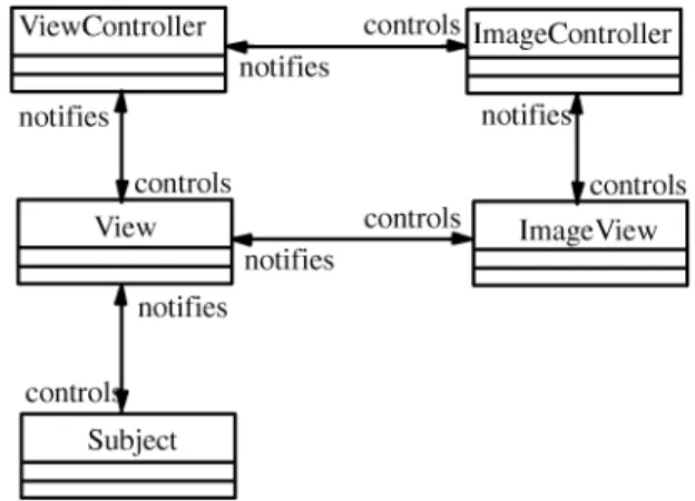
Based on MVC, the DV-Centro framework [4] aims at supporting visual language development, as shown in Fig. 2. It uses the Supervisor-Agent pattern to specify the interactions between the modules in the framework.
The Supervisor-Agent pattern (Fig. 3) assumes that
Supervisor must be able to control Agent's behavior, while
Agentis independent ofSupervisor, except that it may notify
Supervisorin a predefined protocol. Since a Supervisor-Agent pattern indicates a one direction dependency, i.e., the design of Supervisor depends on that of Agent, the DV-Centro framework reduces the number of dependent relationships in a general MVC model. For example,ImageViewin Fig. 2 is independent from other modules, so that it can be developed as a standalone tool.
There are, however, other dependency relationships (as shown in Fig. 4) which have impact on the design and implementation of various modules. For example, View
depends onSubject, which means that it must be designed after the design ofSubject. Any change ofSubjectmay affect
View. On the other hand, as Subject is more application-specific than other modules, the relationships betweenView
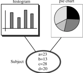
andSubjectshould be reversed. For example, Fig. 5 shows a model having a Subject with two versions of View. The model contains some data values and the views define a histogram and a pie chart. It communicates with its views when its values change and the views communicate with the model to access these values. With the DV-Centro
framework, the histogram and the pie chart have to be designed according to the specifications of the model. But we believe that the design of the histogram and pie chart should be independent of the model so that they are general enough to be predefined in a toolset. The best solution is that Subject and View are designed to be independent of each other so that a subject can use any suitable views without changing itself and the views.
3.2 An Ideal Design Model
The dependence of ViewController on ImageController and
Viewimplies that the high-level control depends on its low-level implementation (e.g.,ImageController). It is, however, desirable that any improvement on the low-level facilities will have no impact on the high-level specification. So a model that removes the dependency relationship between
ViewControllerandImageControlleris more flexible.
Considering the model in Fig. 4 where the link between
ViewController and ImageController has been removed, we find thatViewbecomes a key module because it relates to almost all the other modules. To allow ViewController, Subject, and ImageController/ImageViewto be designed and implemented independently, we propose to reverse the relationship between View and ImageView so that these modules depend only on View. The resulting improved
Fig. 4. Dependency relationships.
Fig. 5. A Subject with two versions of View.
Fig. 6. An improved framework with Supervisor-Agent pattern. Fig. 3. Supervisor-Agent pattern.
framework is shown in Fig. 6, where View serves as an interactive protocol between different modules.
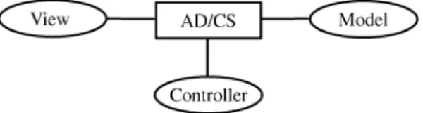
To represent this framework with the MVC notations, we redefine it as an ideal design model as shown in Fig. 7, where Viewcorresponds to ImageControllerand ImageView
in Fig. 6, Model corresponds to Subject, Controller corre-sponds toViewController, andProtocolreplaces the previous
View. This new design model confines the dependencies between the functional modules such that each module can be developed independently.
3.3 The VisPro Design Model
The VisPro design model needs a protocol to define the interaction between its functional modules. The protocol is designed as a combination of an abstract diagram and a
concept space, as shown in Fig. 8. An abstract diagram represents a common internal data structure that may be used to display diagrams in various formats, such as Nassi-Shneiderman diagrams and flowcharts. In an abstract diagram, which can be considered a kind of entity-relationship diagram, directions, distances, data and control flows, joins, contacts, etc., can all be represented as relations between entities. A concept space is a set of specifications for a group of objects that share some common characteristics. If we view a concept space as a lexicon of a visual language, an abstract diagram provides the sentence structure with which the words of the lexicon can be described as visual sentences by associating each word with an entity or a relation of the abstract diagram. The sentences are constructed through direct manipulation by the user on the screen (View) and controlled by Controller. By providing a high-level description of domain concepts in the form of a concept space, Model can interpret the visual sentences. The VisPro design model specifies the roles of Model, View, and Controller, and how they interact with each other in the design model.
. User Interaction Control. View consists of visual objects which can be manipulated directly on the screen. For example, a user may move the mouse onto a visual object and click the left button to trigger an action. When a visual object receives a user input,Viewsends the visual object toController, which interprets the input and sends back a control command indicating whatViewshould do next. For example, Controller may instruct View to pop up a menu to allow the user to act further.
. Diagram Creation. A graph consisting of a set of visual objects can be created on a visual editor controlled by the Controller. Once the graph is constructed, its abstract diagram with domain
concepts is created. The mapping relationships between an abstract diagram and a graph implies that the abstract diagram provides a logical interface understood by all the VPE modules and any modification to the abstract diagram will be reflected on the graph on the screen. A visual editor itself can be a visual object inView.
. Parsing. Model receives parsing demands from
Controller and performs corresponding transforma-tions and computatransforma-tions on abstract diagrams.
. Layout and Animation. If an abstract diagram is associated with visual concepts, the parsing algo-rithm can perform graph layout and animation by operating on the visual concepts. This is because the appearance of a visual object may be changed dynamically when its visual attributes are modified through the corresponding concepts.
In summary, as long as a domain concept space is provided, each module can be designed independently and used with other modules by sharing an abstract diagram and some domain concepts.
4 T
HEV
ISPROT
OOLSETBased on the above design model, we have developed a generic VPE and a set of visual programming tools for generating domain-oriented VPEs [34]. The generic VPE can be customized to any domain VPEs once the domain
Fig. 7. An ideal design model. Fig. 8. The VPE design model.
specifications are provided through these tools. Fig. 9 shows the generation process, which is supported by the following three tools:
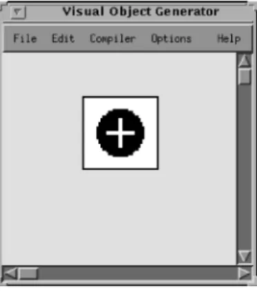
1. The visual object generator is used to specify visual objects with desired appearances to be used in the target visual language.
2. Therule specification generatoris used to provide the parsing specification for the target visual language in the form of graph rewriting rules.
3. The control specification generator is used to specify the control commands for each visual object manipulated in a visual editor, which is to be automatically generated.
In VisPro, the object-oriented language Java serves as a low-level specification tool for details which may not be effectively or accurately specified in these visual specifica-tion tools. This arrangement allows us to precisely construct effective visual programming environments.
The tools are meta visual programming languages that are used to specify domain VPEs through direct manipula-tion. First, the Visual Object Generator is used to construct visual objectsÐit creates the appearance of each visual object and attaches a specification of its behavior produced by other tools, or another visual program, as its logical function. The user then uses the Control Specification Generator to specify the behaviors of constructed visual objects. The specifications will define and automatically generate a visual editor for the target visual language. Finally, with the Rule Specification Generator, the user can describe the grammar of the visual language in forms of graph rewriting rules [32]. The rules can be specified as either graphical productions or textual ones written in Java. Having obtained all the required specifications, the generic VPE becomes customized to the desired domain VPE that integrates the target visual language editor and compiler.
With VisPro, a complete VPL is specified by a lexicon definition and a grammar specification. A lexicon definition describes the VPL's visual objects and the editor with which the visual objects can be used to create a program. A grammar specification (syntax and semantics) defines whether the program is valid and what it means. A visual programming environment is created automatically based on the definition and the specification.
4.1 A Case Study
In the following sections, we will explain the functions and the use of each specification tool by demonstrating the construction of a simple visual programming environment calledsummation. More sophisticated VPEs can be similarly built through the same process but with more interactions. This is the subject of Section 5. Fig. 10 is a snapshot taken during the use of the generated summation. Using summa-tion, one can sum up integers and visualize results. It has three visual classes: numbers, pluses, and scalers. A number stores an integer which can be entered through the keyboard. A plus receives integers from two numbers and produces their summation, also as an integer, which can be stored as a number, sent to another plus, or sent to a scaler for visualization. A scaler visualizes an integer in a vertical bar. In Fig. 10, the maximal (100) and minimal (0) values of the scaler can be changed by entering new values through the keyboard. During the program execution, the displays of the numbers and scalers are changed according to the values sent to them. The following sections introduce the specification tools and explain how summation can be created using these tools.
4.2 Visual Object Generator
In the VisPro framework, a VO generator generates a set of visual classes to suit any special-purpose visual language by editing the predefined visual objects called
VO prototypes. We call such a process customisation. A
constructed visual object is not just an image. It is manipulatable and may be a composite graph, whose components can be manipulated independently.
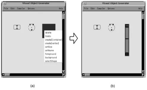
A VO prototype is customizable. Fig. 11a shows two visual classes which have been customized and a VO prototype which is a black box in its original form. One can edit the VO prototype by triggering the editing commands attached to the box, i.e., by clicking the right mouse button when the cursor is over the box. Fig. 11a shows the menu commands of the box. For example, by selecting the command create[node]in the menu items, a node can be created in the box. A subgraph or a node has its own commands which can be popped up in a menu and used for editing the subgraph to obtain a desired shape and color.
For example, to construct a scaler, a command called selectShapecan be triggered from the pop-up menu. This command opens a dialog box which contains a set of graph patterns. If a scaler is selected, the black box will be reshaped to a scaler as shown in Fig. 11b. The dimension and color of the scaler can be edited and also labeled if necessary.
Fig. 11b shows three nodes that have been created: number, plus, and scaler. One may notice that the scaler has a fixed pointer. According to the semantics, the pointer should be created dynamically using the mouse during program editing, and a scaler can have more than one pointer at a time. This is done in the VO generator by specifying its construction style as ªdynamicº (by selecting the menu itemconstructionin the command menu).
We use attributes to parameterize all the three node classes of summation. The domain attribute for the scaler is (pointer, integer), for the number is (ªvalue,º integer), and for the plus is (ªin1,º integer), (ªin2,º integer), and (ªsumº, integer). For example, when we need to set a value 3 to a number object called num, we simply write: num.put(ªvalue,º 3), whereputis a method of the number class.
For a scaler class, a method of its attributes calledput_do can be rewritten so that when the value of a number connected to the pointer of the scaler changes, the position of the pointer will be adjusted accordingly. This modifica-tion is done in Java. Other modules do not need to know this modification when using the scaler, as theputmethod will automatically call the put_do method. Therefore, a method call likescaler.put(pointer, 3) will put an integer 3 into the attributes associated with the scaler and adjust the position of the pointer geometrically.
An edge class can also be created in the VO generator. The edge named flow-toused in summation is defined as shown in Fig. 12, where two little filled rectangles are supposed to be replaced by two nodes in an application when the edge is used. The VO prototype of an edge can be customized by changing its shape, color, and label through the menu items selectShape, selectColor, and setLabel, respectively.
A diagram workbench prototype can be customized to a workbench for a specific VPL with a set of node classes and edge classes. This is obtained via the control specification. A workbench can be accessed, e.g., opened, through its icon. Fig. 13 shows an icon for the summationworkbench,
Fig. 11. Snapshots of visual object construction.
which can be created in another diagram workbench as a special icon.
4.3 Control Specification Generator 4.3.1 Object-Oriented Editing Commands
The process of editing a graph can be seen as a number of steps, each being an execution of a command on the graph. Usually in a visual editor, commands and visual objects are independent of each other. Execution of a command is a selection of both the command and its target graph. In our object-oriented formalism, a graph is an object which encapsulates a set of related commands.
The CS generator is used to visually generate a control specification which can be understood by the object-oriented controller. The controller allows its basic com-mands to be triggered from its canvas and user-defined commands to be triggered from the created visual objects.
The CS generator assigns a set of editing commands and relationships to each visual class. The visual objects instantiated from a visual class can then trigger the assigned commands. The basic editing commands include cut, copy, paste, create, link, open, and properties, which are pre-defined in the VisPro framework. If a user wishes to define additional commands, he/she can specify them in Java. 4.3.2 Command Specification
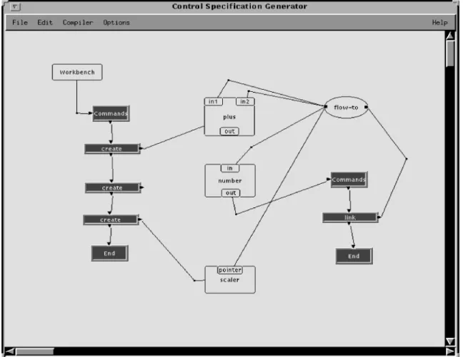
Fig. 14 shows a visual sentence which specifies a part of control in summation. The visual objects handled in the CS generator include edge objects, node objects, and command objects. An edge object, e.g., an ellipse in Fig. 14, is an instance of the edge class defined in the target VPL. Its value is the label type of an edge class, i.e., flow-to, which can be entered or modified through the keyboard. A node object, drawn as an unfilled rectangle, is an instance of a node class. It can be edited to form a
super nodewhich is embedded with some other nodes. For example, the node labeledplusrepresents the plus class of
summation. A command object, i.e., a gray box in Fig. 14, represents an editing command and its value (i.e., delete, link, etc.) can also be entered through the keyboard.
In Fig. 14, the node object labeledWorkbenchrepresents the visual editor forsummation. ªWorkbenchº is a reserved word in the CS generator. The Workbenchnode links to a command list which includes three create commands. A create specification can be generated by interpreting the
link between a command object and a node. A create command node linking a plus node, for example, will be interpreted to produce a command specification create create[plus] plus, where create[plus] is the name of the command menu item.
The number node object is a super node that has two embedded nodesinandout. Theoutnode has one command link, which links to an edge object labeledflow-to. Theflow-to edge object links to the nodesin1, in2, in, andpointer. This indicates that anoutcan link to anin1, in2, in, or apointer insummation.
The control specification diagram in Fig. 14 will produce a list of control specifications as the following:
Workbench 3
create create[plus] plus create create[number] number create create[scaler] scaler
It indicates that three create commands can be triggered from the visual editor canvas. The specification
number.out 1
link connect flow-to
indicates that number.out has a link command named connectand can be linked to other nodes through the edge object instantiated from theflow-toedge class.
The specifications
VE number.out flow-to plus.in1 VE number.out flow-to plus.in2 VE number.out flow-to number.in VE number.out flow-to scaler.point.
describe that the number.out may be linked to visual objects instantiated fromplus.in1, plus.in2, number.in, and scaler.point visual classes, where number.out represents an out node in a number super node. The number.out cannot link to other node classes which are not provided in the specifications.
The control specification diagram in Fig. 14 can be extended to specify the complete behavior of summation. Thus, the CS generator provides an intuitive and easy way to produce the control specification for a visual editor. 4.4 Rule Specification Generator
4.4.1 Graph Grammar
The grammar of a VPL is a collection of graph rewriting rules. A visual sentence can be interpreted by the rules through graph transformations. A graph rewriting rule, also called a production, has two graphs which are called
left graph and right graph. It can be applied to another graph (calledhost graph) in the form of anL-application or
R-application. A production's L-application to a host graph is to find in the host graph aredexof the left graph of the production and replace the redex with the right graph of the production. An R-application is a reverse replacement (i.e., from the right graph to the left graph). A redex is a subgraph in the host graph which is isomorphic to the
right graph in an R-application or to the left graph in an L-application.
For linear textual languages, it is clear how to replace a nonterminal in a sentence by a corresponding sequence of (non)terminals. However, with a visual language that has two-dimensional relationships among the language ele-ments, a far more complicated mechanism is needed to establish relationships between the substitute of a redex and its adjacent elements.
There are three approaches to embedding a graph into a host graph [23]:
. Implicit embedding. Formalisms such as picture layout grammars [10] and constraint multiset gram-mars [16] do not distinguish between vertices and edges. Relationships are implicitly defined as con-straints over their attribute values. Users are not always aware of the consequences of attribute assignments and parsers require considerable time to extract, from attributes and constraints, implicitly defined knowledge about the relationships.
. Embedding rules. Some graph grammars such as the NLC graph grammar [24] and the DNECL graph grammar [3] have separate embedding rules. This approach is easy to implement. However, the rules are often difficult to understand and all known parsing algorithms for productions with embedding rules are either inefficient or imposing very strict
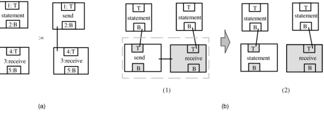
restrictions on the left- and right-hand sides of the productions. Embedding rules are only able to redirect or relabel existing relationships. They cannot be used to define such productions as the one in Fig. 15a, which establishes new relations between previously unconnected vertices.
. Context elements. Context elements can be used to establish the relationships between a newly created graph and the host graph. This approach is the easiest to understand, but an unrestricted use of context elements may complicate the graph rewrit-ing rules. Furthermore, it is difficult to rewrite elements which may participate in a statically unknown number of relationships.
There has been no graph grammar that can handle a wide range of visual languages both effectively and efficiently. For example, if a grammar is expressive enough to represent various types of VPLs, its parsing algorithm usually reaches exponential time [22]. We have proposed a new type of graph grammar known as reserved graph grammar (RGG) [32], which can effectively represent most existing types of diagrams with a parsing algorithm of polynomial time complexity. The RGG combines the approaches of embedding rules and context elements to solve the embedding problem. By introducing context information, simple embedding rules can be sufficiently expressive to handle complicated programs. In order to identify any graph elements which should be reserved
during the transformation process, we mark each iso-morphic vertex in a production graph by prefixing its label with a unique integer. The purpose of marking a vertex is to preserve the context.
We impose an embedding rule which states that if a vertex in the right graph of the production is unmarked and has an isomorphic vertex v in the redex of the host graph, then all edges connected to v should be completely inside the redex. With the above embedding rule, each application of a production can ensure that a graph can be embedded in a host graph without creating dangling edges. The example in Fig. 15b illustrates the R-application process, where the host graph (b(1)) has an isomorphic graph (enclosed in a dashed box) of the right graph in the production of Fig. 15a. The isomorphic graph is a redex. The vertices corresponding to the isomorphic vertices marked in the right graph of the production are painted gray. The transformation deletes the redex while keeping the gray vertices. Then the left graph of the production is embedded into the host graph, as shown in Fig. 15b(2), while treating a marked vertex in the left graph the same as a gray vertex having the same mark. We can see that the marking mechanism allows some edges of a vertex to be preserved after transformation. For example, in Fig. 15b, two edges from B to T are preserved after transformation.
Fig. 16 shows a reserved graph grammar forsummation. The grammar completely describes the syntax of a valid
summationdiagram. For example,
. plus.in1 (or plus.in2, or number.in) can connect to plus.outor number.outbut cannot connect to more than one destination.
. plus.out (or number.out) can link to one or more destinations, which include number.in, plus.in1, plus.in2andscaler.pointer.
The graph grammar also specifies the semantic aspects. Fig. 17 shows a validsummationdiagram. According to the semantics, subgraph 1 must be interpreted first by applying the grammar rule of Productionh3i. Subgraph 2 should be done next, followed by subgraph 3. Otherwise, an incorrect result will be produced. For example, if subgraph 2 is interpreted first, since its numbers do not have the correct values (from subgraph 1), the result of subgraph 2 will be incorrect. Such an order of applications is not allowed according to the graph rewriting system which dictates that
a rule can be applied to an unmarked visual object only if all of the object's edges are matched by the rule.
A detailed description and formal treatment of reserved graph grammars and their parsing complexity can be found in [32].
4.4.2 Parsing
Parsing a diagram takes two phases: syntax parsing and semantics parsing. Syntax parsing is to check whether the diagram is valid. If a diagram is eventually transformed into an initial graph (i.e.,) by the graph rewriting rules, it is valid. Semantics parsing is to produce a result from a diagram. The result is meaningful only when the diagram is valid. In a translation process, say from a diagram to a textual specification, the syntax and semantics can usually be specified in the same set of graph rewriting rules. In this case, the graph transformation process checks the syntax and translates a graph into a textual specification at the same time. For an executable diagram, this is not always the case. The syntax and semantics specifications of a Petri net visual language, for example, should be specified separately. This is because a Petri net can be executed repeatedly, while the syntax checking must be done in finite steps. Forsummation, the syntax and semantics can be specified with the same set of graph rewriting rules, as shown in Fig. 16.
To create a parser for a VPL, one must write a piece of code (i.e., action) in Java for each graph rewriting rule. An action performs computation over the attributes of a redex (a subgraph of the program which is isomorphic to the right graph of a production) when the production is applied. Writing an action code is like writing a standard exception handler in Java by treating each attribute as an object. The actions of the graph rewriting rules ofsummationare listed in Fig. 16. With the actions, the desired results can be produced after the graph transformation. For example, the action of Productionh3iis as follows:
action (AAMGraph g) { Attributes attributes=g.getAttributes(); int sum=(int)((Property)attributes(1) .get(ªvalueº))+(int)((Property) attributes(2).get(ªvalueº)); (Property)attributes(3).put(ªsumº, sum) }
The action takes a graphg as its input. This graph has a matching redex isomorphic to the right graph of Productionh3i. To facilitate the access of attributes in the redex, an array referring to required attributes is first produced through the method g.getAttributes(). The array member attributes(2), for example, refers to the attributes of the super node which has aA ref 2, i.e.,number[2:2] in the figure. The sum is calculated by summing up values of two matched numbers. It is then stored in attributes(3) as a result.
A parsing algorithm has been proposed and implemen-ted in the tool and its parsing complexity has been proven to be polynomial under a constraint condition [32].
4.4.3 Rule Specification
The RS generator facilitates the rule specification. Fig. 18 is a snapshot when using the RS generator, where two kinds of nodes (left graph node and right graph node) are used to represent the left graph and the right graph of a production. For example, the node labeled Lh3iis a left graph node for Productionh3i. The node labeledDuplex is the head of the rule list. It indicates that the rules are applied in a duplex mode such that a production is created by linking a left graph node and a right graph node. Each graph node has a subeditor for defining a graph in the node. In addition, a
textual editor workbench can be triggered from the right graph to be used for writing action codes.
Fig. 18 shows a snapshot of creating Productionh3iof the
summationgraph grammar, where two windows are opened
for editing the left graph and the right graph of the production, respectively. Also there is a textual window for editing the action. Thus, the RS generator provides visual editors for specifying the graph rewriting rules and a textual editor for specifying actions. The RS generator can compose complete graph rewriting rules automatically by interpreting the connected editors.
4.5 Implementation
The VisPro architecture includes seven functional modules, as shown in Fig. 19:
. The configuration interpreter receives the configura-tion specificaconfigura-tion, and transfers the lexicon defini-tion of the specificadefini-tion to the user interface and the grammar specification to the parsing module.
. The user interface controls the interaction between users and the VisPro tools.
. The underlying structure manages the diagrams which are being edited.
. During parsing, the logical structure module creates and manages the logical graph converted from the underlying structure of a diagram.
. The parsing module is designed to parse the logical structure of a diagram using the reserved graph grammar formalism.
. The documentation module automatically records edited diagrams and parsing results.
. The actions module collects actions for each VPL from grammar specifications. The collected actions are represented as a Java program and dynamically linked to the parsing module during execution. The above VisPro architecture is implemented in Java, an object-oriented language. One advantage of using Java is
that it is platform independent, so that the system can be ported to different platforms. Another advantage is that Java is developed for network programming. This char-acteristic can support the construction of VPLs which allow visual programming for the Internet and distributed applications.
5 G
ENERATINGD
ISTRIBUTEDP
ROGRAMMINGENVIRONMENT
PEDS
This section demonstrates the application of VisPro in generating a distributed programming environment, called PEDS [33]. It describes the features of PEDS and then shows how the PEDS environment is generated using VisPro. 5.1 PEDS
In a heterogeneous distributed system, the processors and software resources available are of different types. It is often difficult for a user to interface cooperative processes which are implemented with different software resources and located on different processors [12], [28]. Unfortunately, there are few systems that are aimed at providing shared processing power in a distributed environment, while taking into account the utilization of software resources of the environment.
The programming environment for distributed systems, or PEDS, has the following important features:
. It consists of a set of tools (visual languages) which can cooperate with each other in order to solve complicated distributed problems.
. It supports developing a distributed program gra-phically, so that resources sharing and mapping can be visually specified. Moreover, different graph formalisms, such as control flow graphs and Petri Nets, can work consistently in a single environment.
. A distributed program is divided into several local processes, which may be located on multiple physical machines. Local processes can be written using different tools based on existing software resources of the distributed system such as compi-lers and program libraries.
. A user can have the freedom of control over the mapping of processes to processors. With a high-level graphical notation, a user can specify the processor assignments completely, partially, or leave it entirely up to the environment.
Based on a distributed graph model [6], PEDS can be used to implement a wide range of distributed programs. Each distributed program is modeled as a set of related diagrams. The components of a diagram are implemented with existing software resources of the distributed system. The construction process is independent of any specific distributed system and a constructed program can be mapped onto different configurations by a flexible mapping facility.
5.1.1 Graph Modeling of Distributed Applications When designing distributed programs, programmers com-monly draw informal directed graphs showing distributed
structures [35]. These graphs abstract away the details of the nodes being designed and concentrate on their interactions. The advantage of this is that the programmer can specify the distributed structure without concern about the internal working of each node.
PEDS uses a graph abstraction method to represent distributed programs. It divides a distributed program into several local processes (LPs) and defines their interactions. Each LP can be allocated on a processor in a distributed system. An LP is characterized by the fact that all work initiated in it is, mostly, limited to its sphere of control; it essentially executes independently of other LPs except for specific points in its processing when it needs to interact with other LPs.
The process of creating a distributed program is then divided into two steps: drawing an overall graph and creating corresponding LPs. A graph-based visual distrib-uted programming language can help realize this process [6]. With the visual programming language, we separate the specification of LPs from that of synchronization and
communication, and express synchronization and commu-nication directly (but abstractly) using graphs.
An LP is defined as a graph node, which can have a set of input and output ports. With these ports, a graph illustrates the interaction among LPs. As LPs are located on distributed processors, the interactive behavior de-scribes the message-passing mechanism that is performed between distributed processors. A processor can send messages directly only to a subset of the processors with which it is directly connected. Its directly connected processors are called its neighbors. For communication with nonneighbors, a routing algorithm is needed. Routing is the term used to describe the decision procedure by which a processor selects one of its neighbors to send a message to an ultimate destination.
5.1.2 Programming Tools
In PEDS, various distributed tools are used to support implementing the mentioned functionalities. They can cooperate with each other to create sophisticated distributed
programs. Such tools, which will be called workbenches, include:
. High-Level Process Flow Diagram (HPFD) workbenchis a process flow diagram providing a high-level control structure over a set of processes, whose details can be specified in other workbenches.
. High-Level Petri Net (HLPN) workbenchis a modeling tool for specifying the high level behavior of a task using Petri net. Each of its transitions can be connected to a workbench, with which the transition specification can be provided.
. Java workbench provides a platform for editing and compiling Java programs.
. Supporting workbench is used to specify a set of
available software resources and their relationships for mapping processes to processors.
. Net workbench is for specifying the configuration of processors and their interconnecting network (e.g., a distributed system).
. Distributed workbench(Fig. 20) is the top-level work-ing environment that is used to configure all the other workbenches to form an integrated distributed application.
A distributed program modeled with a set of HLPN workbenches and HPFD workbenches is linked to a supporting workbench for resource mapping, which in turn links to a net workbench for finding proper set of processors. PEDS is, therefore, a hierarchical programming environment supporting multiple programming paradigms. 5.2 Generation of PEDS Using VisPro
This section focuses on how to construct the PEDS hierarch-ical environment and implement interactions between different subvisual languages using the VisPro system. 5.2.1 Hierarchical Environment
An icon in the PEDS interface represents a window, called a
workbench, which can be opened and operated upon and can include child icons. The main window in PEDS is an icon window, called management-win, where various icons can be created and managed. Apart from themanagement-win, there are other windows: HLPN workbench, HPFD bench, Java workbench, supporting workbench, net work-bench, and configuration workbench.
In an icon window, each workbench represents a program (or a specification). For example, when one wants to create a Petri net, he/she can create anHLPN-icon, (i.e., an icon for HLPN window). By opening the HLPN-icon, one can create a Petri net. Thus, the HLPN-icon uniquely represents the created Petri net.
Fig. 21 shows the hierarchical programming environ-ment of PEDS. It has a main icon window in which some child icons have been created. A child icon window and a HLPN workbench are also shown in the figure. They can be triggered from icons in the main window.
Generating such a hierarchical programming environ-ment is easy in the VisPro system. First, one can create icon classes in the VO generator for each of the workbenches. Then the control specifications for the icons can be created, which include
ND-has-node management-win management-icon ND-has-node management-win HPFD-icon
ND-has-node management-win HLPN-icon ND-has-node management-win Java-icon
ND-has-node management-win supporting-icon ND-has-node management-win net-icon
ND-has-node management-win configureicon
It indicates that seven classes of icons, namely, manage-ment-icon, HLPN-icon, HPFD-icon, Java-icon, supporting-icon, net-supporting-icon, and configure-icon, are created in a management-win. Each of the child icons created in the management-win may open a corresponding window (i.e., workbench). This can be specified as:
ND-has-workbench management-icon management-win
ND-has-workbench HLPN-icon HLPN-win ...
The first item specifies that one can open a management-win on a management-icon object. Similarly, the second item indicates that aHLPN-wincan be opened through an
Fig. 20. Distributed workbench. Fig. 19. The VisPro architecture.
HLPN-icon, where HLPN-win is the workbench class for HLPN. In addition, commands should be added to each of the icon classes, such as an open operation. For example:
open open-management management-win
specifies a menu item namedopen-managementwhich can be triggered to open amanagement-win.
The VisPro framework will create a command system over each of the icons according to the control specification. Icons and their commands provide a mechanism for hierarchically specifying distributed programs. For a hier-archical programming environment, interactions between graph nodes and workbenches should also be created. 5.2.2 Construction of Interactions
A workbench w1 may be used to specify a subtask of another workbenchwby linkingw1's own icon with a node of w. As an example, we use a HLPN workbench to illustrate the interaction between different specification levels. Fig. 22 shows the visual objects used in a HLPN workbench. Normal objects in a Petri net are transitions and places. An annotation object can specify the annotation for a visual object by linking to the visual object. To specify the data transfer mechanism, we construct two classes:
input portandoutput port. An input port can be used in a transition to specify the input information (i.e., name, type, etc.). When an input port used independently, it represents an input from outside and is called a global input port. Similarly, we have output ports and global output ports. Annotations can be given to an input port or an output port to specify its type and name. The reference object in a transition is used to link to another workbench for specifying the transition details.
Fig. 23 shows two HLPN workbenches, where work-bench (b) is used to specify a transition in workwork-bench (a). To transfer data correctly between two workbenches, each port of the transition is annotated. In workbench (b), two global input ports, annotated asint countandint work-id, have the same annotations as the input ports of the transition. Input ports with the same annotations are taken as the same port. Thus, data accepted in the port annotated as int count in workbench (a) is accepted in the port annotated asint count in workbench (b). How data is transferred in output ports can be specified in a similar fashion.
To implement the data transfer mechanism, we associate a transition with anAttributeconcept if the transition refers to another workbench such that its ports are specified as attributes in the concept. For example, the input port
labeled int count is specified as attribute(ºint count,º parameter), where parameter is data transferred to the port. In the subworkbench, a global input port will check theAttributeconcept and access the parameter it needs. In this way, data are transferred between different work-benches properly.
After the user has specified the hierarchical program-ming environment of PEDS and the interactions between the workbenches, the VisPro framework becomes custo-mized to PEDS.
5.2.3 Summary
PEDS is a visual environment for distributed programming. A distributed visual program can be created in PEDS with different tools. This section has specified how to generate PEDS using the VisPro system. The management of the environment is described in the control specification. On the other hand, interactions between different workbenches can be specified in the annotations and with the Attributes
concept. PEDS, a hierarchical programming environment with multiple paradigms, thus, is created by customizing the VisPro framework through specifications.
6 CONCLUSION AND
FUTURE
WORK
This paper has presented a generic visual language generation environment with a hierarchical specification structure and multiple programming paradigms. To ease the development of VPLs, we have proposed a VisPro
design model that divides any VPE into independent functional modules and defines a protocol supporting the interaction between the modules. The VisPro toolset with its framework has been developed based on the above design model, which can be used to generate diagrammatic VPLs. The toolset consists of three specification tools, each of which facilitates one aspect of the construction of VPLs in the VisPro framework. These tools are visual languages themselves so that the target language properties and the domain specifications can be visually described by direct manipulation.
The VPL construction process using the VisPro toolset is similar to the textual language construction process using Lex/Yacc. The process can be described as customization, i.e., the VisPro framework can be customized to any target visual language with a set of domain specifications provided through the tools. The VisPro framework and the specification tools together provide a complete support for the VPL generation. They can be used to generate a wide range of visual programming environments easily.
We will be applying the graph grammar techniques to assist verifying the graphical design of Web sites. The Web site design tool will be a special-purpose visual language generated from VisPro. Our other future work includes the application of the techniques used in VisPro to multimedia presentations [30]. The reserved graph grammar can be designed to represent a general-purpose multimedia architecture. The system constructed based on such an architecture will parse the input specifications of the
domain-oriented multimedia documents (in the form of nodes and links) and produce a derivation tree. Then the graph grammar rules are applied to translate the deriva-tion tree into a set of media objects, together with their spatial and temporal relationships. A layout algorithm [2] can later be applied to the media objects to arrange the final display layout.
REFERENCES
[1] A. Ananda and B. Srinivasan, Distributed Computing Systems: Concepts and Structures.Los Alamitos, Calif.: IEEE CS Press, 1991.
[2] G. Di Battista, P. Eades, P. Tammassia, and I.G. Tollis, ªAlgorithms for Drawing Graphs: An Annotated Bibliography,º
Computational Geometry: Theory and Applications, vol. 4, no. 5, pp. 235-282, 1994.
[3] F.J. Brandenburg, ªOn Polynomial Time Graph Grammars,ºProc. Fifth Conf. Theoretical Aspects of Computer Science,pp. 227-236, 1988.
[4] P.C. Brown, ªSatisfying the Graphical Requirements of Visual Languages in the DV-Centro Framework,ºProc. 13th Symp. Visual Languages (VL '97),pp. 84-91, Sept. 1997.
[5] M.M. Burnett, ªSeven Programming Language Issues, Margaret Burnett,º Visual Object-Oriented Programming,A. Goldberg and T. Lewis, eds., pp. 161-181, 1994.
[6] J. Cao, F. Fernando, and K. Zhang, ªDig: A Graph-Based Construct for Programming Distributed Systems,º Proc. Second Int'l Conf. High Performance Computing (HiPC '95),pp. 417-422, Dec. 1995.
[7] S.K. Chang, M.J. Tauber, B. Yu, and J.S. Yu, ªA Visual Language Compiler,ºIEEE Trans. Software Eng.,vol. 15, no. 5, pp. 506-525, May 1989.
[8] G. Costagliola, G. Tortora, S. Orefice, and A.D. Lucia, ªAutomatic Generation of Visual Programming Environments,º Computer,
vol. 28, no. 3, pp. 56-66, Mar. 1995.
[9] A. Goldberg, M. Burnett, and T. Lewis, ªWhat Is Visual Object-Oriented Programming?º Visual Object-Oriented Programming,
M. Burnett, A. Goldberg, and T. Lewis, eds., 1994.
[10] E.J. Golin, ªA Method for Specification and Parsing of Visual Languages,º PhD thesis, Brown Univ., May 1991.
[11] E.J. Golin and T. Magliery, ªA Compiler Generator for Visual Languages,º Proc. Ninth IEEE Symp. Visual Languages (VL '93),
pp. 314-323, Aug. 1993.
[12] A. Grimshaw, J. Weissman, E. West, and E. Loyot, ªMetasystems: An Approach Combining Parallel Processing and Heterogeneous Distributed Computing Systems,º J. Parallel and Distributed Computing,vol. 21, no. 3, pp. 257-270 1994.
[13] M. Hirakawa, Y. Nishimura, M. Kado, and T. Ichikawa, ªInter-pretation of Icon Overlapping in Iconic Programming,º Proc. Seventh IEEE Workshop Visual Languages (VL '91),pp. 254-259, Oct. 1991.
[14] M. Kleyn and A High, ªLevel Language for Specifying Graph-Based Languages and Their Programming Environments,º PhD thesis, The Univ. of Texas at Austin, Aug. 1995.
[15] G.E. Krasner and S.T. Pope, ªA Cookbook for Using the Model-View-Controller User Interface Paradigm in Smalltalk-80,º
J. Object-Oriented Programming,vol. 1, no. 3, pp. 26-49, Aug. 1988.
[16] K. Marriott, ªConstraint Multiset Grammars,º Proc. 10th IEEE Symp. Visual Languages (VL '94),pp. 118-125, Oct. 1994.
[17] J.D. McWhirter and G.J. Nutt, ªEscalante: An Environment for the Rapid Construction of Visual Language Applications,ºProc. 10th IEEE Symp Visual Languages (VL '94),pp. 15-22, Oct. 1994.
[18] M. Minas and G. Viehstaedt, ªDiaGen: A Generator for Diagram Editors Providing Direct Manipulation and Execution of Dia-grams,ºProc. 11th IEEE Symp. Visual Languages (VL '95),pp. 203-210 Sept. 1995.
[19] B.A. Myers, ªTaxonomies of Visual Programming and Program Visualisation,ºJ. Visual Languages and Computing,vol. 1, pp. 97-123, 1990.
[20] J.V. Nickerson, ªVisual Programming,º PhD thesis, Dept. of Computer Science, New York Univ., 1994.
[21] Rational Corporation, UML Document Set V1. 1, 1997, http:// www.rational.com.
[22] J. Rekers and A. SchuÈrr, ªA Graph Based Framework for the Implementation of Visual Environments,ºProc. 12th IEEE Symp. Visual Languages (VL '96),Sept. 1996.
[23] J. Rekers and A. SchuÈrr, ªDefining and Parsing Visual Languages with Layered Graph Grammars,ºJ. Visual Languages and Comput-ing,vol. 8, no. 1, pp. 27-55, 1997.
[24] G. Rozenburg and E. Welzl, ªBoundary NLC Graph GrammarsÐ-Basic Definitions, Normal Forms, and Complexity,º Information and Control,vol. 69, pp. 136-167, 1986.
[25] D. Schefstrom and G. van den Broek,Tool Integration-Environments and Frameworks.Chichester, England: John Wiley, 1993.
[26] P. Salis, G. Tate, and S. MacDonell,Software Engineering. Addison-Wesley, 1995.
[27] A. SchuÈrr, A. Zundorf, and A. Winter, ªVisual Programming with Graph Rewriting Systems,ºProc. 11th IEEE Symp. Visual Languages (VL '95),pp. 326-333, Sept. 1995.
[28] S. Shatz,Development of Distributed Software.New York: Macmil-lan, 1993.
[29] C. Upson, T. Faulhaver, D. Kamins, D. Laidlaw, D. Schlegel, J. Vroom, R. Gurwitz, and A. Van Dam, ªThe Application Visualization System: A Computational Environment for Scientific Visualization,º IEEE Computer Graphics and Applications, vol. 9, no. 7, pp. 30-42, July 1989.
[30] L. Weitzman and K. Wittenburg, ªAutomatic Presentation of Multimedia Documents Using Relational Grammars,ºProc. ACM Int'l Conf. Multimedia,pp. 443-451, Oct. 1994.
[31] N. Wilde and C. Lewis, ªSpreadsheet-Based Interactive Graphics: From Prototype to Tool,ºACM SIGGHI Special Issue, Proc. CHI '90,
pp. 153-159, Apr. 1990.
[32] D.-Q. Zhang and K. Zhang, ªReserved Graph Grammar: A Specification Tool for Diagrammatic VPLs,ºProc. 13th IEEE Symp. Visual Languages (VL '97),pp. 284-291, Sept. 1997.
[33] D-Q. Zhang and K. Zhang, ªOn A Visual Distributed Program-ming Environment and Its Construction by a Meta Toolset,ºProc. SEKE '98Ð10th Int'l Conf. Software Eng. and Knowledge Eng.,June 1998.
[34] D.-Q. Zhang and K. Zhang, ªVisPro: A Visual Language Generation Toolset,º Proc. 14th IEEE Symp. Visual Languages (VL '98),pp. 195-202, Sept. 1998.
[35] K. Zhang, X. Ma, and T. Hintz, ªThe Role of Graphics in Parallel Program Development,ºJ. Visual Languages and Computing,vol. 10, no. 3, pp. 215-243, 1999.
Kang Zhang received his BEng in Computer
Engineering from the University of Electronic Science and Technology, China, in February 1982; and PhD from the University of Brighton, UK, in 1990. He is currently an associate professor of computer science at the University of Texas at Dallas. He has held positions as a Lecturer and Senior Lecturer at Macquarie University, Sydney, Australia; a Research As-sistant and SERC Postdoctoral Fellow at the University of Brighton, UK; and a Software Engineer at the East-China Research Institute of Computer Technology, Shanghai, China. Dr Zhang's current research interests are in the areas of software visualisation, parallel programming tools, visual programming, and Internet computing. Dr Zhang is a senior member of IEEE.
Da-Qian Zhangreceived the BEng and MEng
degrees in computer engineering from Zhejiang University, China, in 1985 and 1993, respec-tively; and the PhD degree in computer science from Macquarie University, Sydney, Australia in 1998. He is a software engineer at Corel Corporation, Ottawa, Canada. Dr. Zhang was an assistant lecturer at Hangzhou University, China, for five years, before pursuing his PhD at Macquarie University. After his PhD, he became a software developer at Daedalian System Group, Canada, and then joined Corel Corporation.
Jiannong Caoreceived the BS degree (1982) from Nanjing University, China, the MS degree (1986), and PhD degree (1990) from Washing-ton State University, all in computer science. He has been on the faculty of computer science at James Cook University (Queensland, Australia), University of Adelaide (South Australia, Austra-lia), and City University of Hong Kong. He joined the Hong Kong Polytechnic University in 1997, where he is currently an assistant professor. Dr. Cao's research interests include parallel and distributed systems, computer networks, Internet computing, fault tolerance, and program-ming methodology and environments. He has published more than 60 technical papers in the above areas, which have appeared in international journals and conference proceedings. His recent research has focused on how to build high-performance, fault-tolerant distributed systems and applications on the Internet. Dr. Cao is a member of ACM and a senior member of the IEEE.