DashBoard
Brad Levin - [email protected]
Kyle King - [email protected]
Computer Engineering Department
Under the advisement of Dr. Andrew Danowitz
California Polytechnic State University, San Luis Obispo, United States
Table of Contents
Introduction 2
Project Overview 2
Project Outcomes and Deliverables 2
Engineering Specifications 4 Bill of Materials 4 Hardware 4 Software 4 Target Audience 5 Background 6 System Overview 7 Raspberry Pi 3 7 ATmega164P microcontroller 7
MC74ACT273NG Octal D Flip Flops 8
LED Array 8
Architecture - Control Flow 9
Full Board Design 9
Prototype Design 12
Construction 14
Acrylic Box 14
Wiring 15
Future Steps 17
Replace LEDs with Magnets 17
Full-Scale Model 18 PCB 18 RFID 19 Network Connectivity 19 Tunability 20 Appendix A 21 Appendix B 25 Appendix C 27 Appendix D 30
Introduction
Project Overview
Modern gamers are always looking for new and exciting ways to play board games. Our senior project, DashBoard, is intended to capitalize on this interest and upgrade board games to have pre-programmed moves and easy piece moving. It is a proof-of-concept project for a
programmable chess-style game board using an electromagnet array to move the pieces around the board. With an easily programmable interface with the Raspberry Pi 3, users can make their own programs or find ones others have made online to move pieces in creative ways.
The only similar product to the DashBoard is the SquareOff, a chess board that can simulate playing against another player or can be used to play against another player remotely. SquareOff is also very expensive at around $387. The main difference is that DashBoard is more easily programmed by the users. DashBoard allows a more adaptable user interface and more user participation.
Project Outcomes and Deliverables
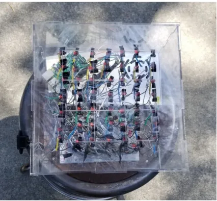
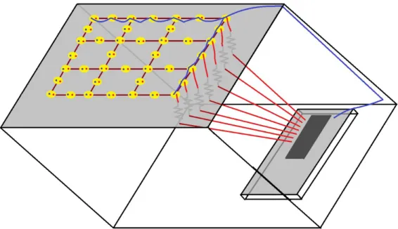
The project deliverables are to be a proof-of-concept LED array programmable with a Raspberry Pi 3 and ATmega164P along with programs to access each individual LED encased in a clear, laser cut acrylic box with holes for access and a board of 3x3 etched squares. It is a smaller scale than a chess board, with 9 squares and 49 programmable points. Only the Raspberry Pi is to be programmable by the user, allowing for the user to activate LEDs to simulate moving pieces. The current Raspberry Pi has programs for turning on individual LEDs, turning on all of the LEDs, and has base code for programming pieces on individual squares. This project is meant to be scalable, with the ability to eventually support an 8x8 grid of squares with 317 electromagnets to move game pieces around.
Figure 1: Top View of DashBoard
Engineering Specifications
Bill of Materials
Hardware
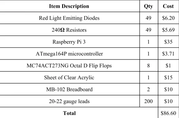
Item Description Qty Cost
Red Light Emitting Diodes 49 $6.20
240𝛀 Resistors 49 $5.69
Raspberry Pi 3 1 $35
ATmega164P microcontroller 1 $3.71 MC74ACT273NG Octal D Flip Flops 8 $1
Sheet of Clear Acrylic 1 $15
MB-102 Breadboard 2 $10
20-22 gauge leads 200 $10
Total $86.60
Table 1: Hardware Bill of Materials
Software
Item Description
Vim Text Editor Python 2.7
Raspbian Operating System Atmel Studio 7.0 Adobe Illustrator Table 2: Software Bill of Materials
We decided to use the Raspberry Pi 3 for easy interfacing and to make it easier for future users to program the board. The ATmega164P microcontroller is a cost effective controller to eventually send out commands to an array of 317 of MC74ACT273NG D Flip Flops. The microcontroller and flip flops are both hosted on the breadboard. We decided to use clear acrylic for the outer shell because of former experience and ease of modification of the acrylic. On the Raspberry Pi 3’s operating system, Raspbian, we used the Vim text editor and Python 2.7 to make the suite of functions for use for the board. Atmel Studio was used for programming the ATmega164P microcontroller in C. Adobe Illustrator was used to design the template for laser cutting the acrylic.
Target Audience
Our target audience is hobbyists and people with an interest in creating and playing board games. Game developers and software developers with some disposable income are probably what we’re looking for. They preferably have experience programming in Python, however, Python is not necessarily for using the board. Experience with Raspberry Pi and Raspbian are preferred but not required for use.
Background
The inspiration for this project first came when we realized the idea of making a real-world wizard chess was workable. All we need are some magnets and digital logic to control them. We found a similar product called “Square Off”, but their design featured a mechanical claw-like structure. We realized that this is the ideal setup for making a hands-free chessboard due to the fluid movements that it could do. But, our magnet array idea had its own merits. Even if piece movements were jerky, an array would be able to coordinate multiple pieces at once. This isn’t useful for games like chess, but it’s a cool idea to think of games it could be useful for.
Role-Playing Games like Dungeons and Dragons comes to mind. The thing that really pushed us to explore the project more was the thought of games that haven’t been made yet. We envisioned games that could incorporate pieces moving in real-time, a network component, a
piece-detection/response scheme, and behaviors customized to a user. The best part is, once the system was created, developers everywhere could develop for it to introduce their own creativity to the platform, and find purposes for it we would never think of.
Although this system is far from incorporating those features, it is a proof-of-concept that gets us excited about the possibilities in using a programmable magnet array to develop games.
System Overview
Raspberry Pi 3
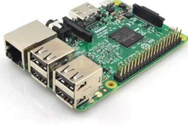
The Raspberry Pi 3, using Python 2.7, is used to interface with the ATmega164P
microcontroller. It uses the Raspbian operating system and requires the use of a monitor with an HDMI input, MicroUSB power input, mouse, and keyboard. Using GPIO pins 2, 3, 4, 17, 27, 22, 10, and 9, and control pins 5, 6, 13, 16, and 27 the raspberry pi can support sending an 8 bit number to up to 5 peripheral microcontrollers, or PMCs. All of the GPIO pins are connected to all of the input pins for the PMC and activation depends on which of the control pins is activated. This can then be used to send commands to activate or deactivate the LED for up to 317 outputs. Because this is a smaller scale system, the system only uses one PMC.
Figure 3: Raspberry Pi 3
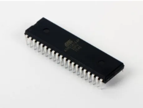
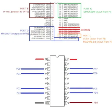
ATmega164P microcontroller
Our PMC, the ATmega164P, is used to take an input and control the output to an array of D Flip Flops. It is programmed using Atmel Studio 7.0 on the Windows 10 Operating System in C. The PMC takes an 8 bit input from the Raspberry Pi 3, processes which D Flip Flop is the correct one to output to, and outputs to the proper D Flip Flop.
Figure 4: ATmega164P microcontroller
MC74ACT273NG O
ctal D Flip Flops
The MC74ACT273NG Octal D Flip Flops (DFFs) are used to store and output high or low inputs coming from the ATmega164P (PMC) going to the LED array.
Figure 5:MC74ACT273NG Octal D Flip Flop
LED Array
The output from the MC74ACT273NG Octal D Flip Flop is then transmitted to a 240𝛀 resistor attached to a red Light Emitting Diode (LED). The LED is meant to represent where an
electromagnet is meant to go. The LED is then connected to a common ground on all of the LEDs, completing the circuit.
Architecture - Control Flow
Full Board Design
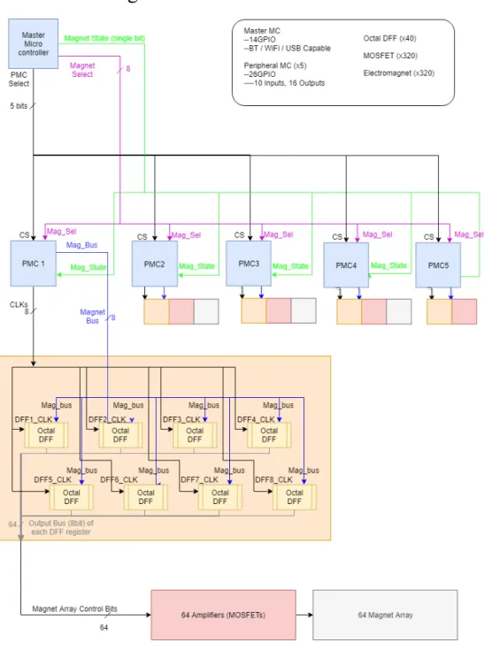
This diagram shows the overall design of the system. Control in the system is headed by the Master Microcontroller (MC), which is a Raspberry Pi 3 for this prototype. The user can enter an address into the MC, which converts it to a series of control signals that it sends to a determined Peripheral Microcontroller (PMC). These control signals are named PMC_Select, Magnet_State, Magnet_Address. PMC_Select is a 5 bit bus used to control which of the 5 PMCs the selected magnet is addressing. Magnet_State is a single-bit signal that determines what to set the magnet’s state to (ON or OFF). Lastly, Magnet_Address is an 8-bit bus used to address the magnet in a way that is independent of which PMC is selected. Here’s an example to highlight the operation of the MC:
Suppose the MC sets the magnet on the sixth row and second column (row=5,col=1) to be set HIGH.
The MC must determine which PMC controls that magnet (see the Full Board Addressing Diagram), which in this case would be the second PMC, PMC1. Further, the Pi would need to know which address (0-63) the magnet is on PMC1. In this case it would be the eighteenth magnet (address 17).
The MC’s output signals would be:
PMC_Select = 0b00010 //BIT1 to select PMC1 Magnet_State = 0b1 //Set Magnet HIGH = ‘1’ Magnet_Address = 0x11 //Specify address 17
The PMCs each have input control signals which are a copy of the MC output control signals (except the PMC_Select bus, which is split into 5 separate ‘CS’ inputs -- one per PMC). The PMCs also have their own outputs, which are Magnet_Bus and CLKs. Magnet_Bus is an 8 bit bus that the PMC wants to write to an Octal Data Flip Flop IC (DFF). CLKs is an 8-bit bus of chip selects for the DFFs, similar to how PMC_Select works for selecting which PMC the MC wants to control. It is named CLKs instead of DFF_Select to highlight that it updates on a timer in order to give the flip flops a steady clock signal to synchronize with, which could be useful if more (synchronous) hardware is added later.
The PMCs are inactive until the MC asserts its chip select input. This triggers an interrupt on the PMC which latches the control inputs from the MC. It updates its internal variables that hold the states of the DFFs it controls based on the address and state that was provided. When the timer on the PMC goes off, the PMC updates its output Magnet_Bus pins based on the bits stored in its internal variables for the currently selected DFF (as controlled by the CLKs signal). It then pulses the CLKs signal of the DFF it wants to write to, and updates the variable that specifies which DFF to select next.
Suppose the PMC receives a CS rising edge, and reads in an address of 0x1F (31) and a state of 1 (HIGH) from the MC. Since every DFF the PMC controls only handles 8 magnets, address 31 will be on the fourth DFF (which handles address 24-31). Since it’s the last address in that address range, 31 would be the last pin on the selected DFF (DFF3).
The PMC’s behavior (in this situation) would be: ISR(RISING_EDGE_CS_PIN) {
//Read in address and state
DFFs[3] &= ~BIT7; //update corresponding variable }
ISR(TIMER) {
if(DFF_to_update == DFF3)
MAGBUS = DFFs[3]; //update output bus CLKs = DFF3; //enable select
CLKS = 0; //end pulse of select
DFF_to_update = nextDFF; //update next-select variable }
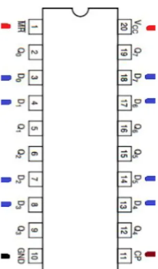
The DFFs are ICs that are collections of 8 data flip flops which all set on a common clk edge, which is the output of the PMC (CLKs). Its outputs are the 8 outputs of those flip flops.
Figure 8: Pinout of DFF IC
Here, the pins marked with:
-RED get powered by VCC (3.3V or 5V, both work in the system), -BLACK goes to GND
-BLUE are inputs from the PMC -WHITE are outputs
Lastly, the system then connects these DFF outputs as control signals to MOSFETs (at the gates), and those MOSFETs run in series to our magnets to switch them on and off.
Prototype Design
The prototype featured in this paper implements this same control scheme. The only change in digital control lies in magnet addressing - the full board and 3x3 prototype wire rows and columns differently. This isn’t a problem; in fact it shows off the modular design of the system. This modularity is useful because it allows all of the PMCs to be programmed off of the same code, and it allows changes to board size/layout/wiring (such as this one) to be quickly solved by changing the small code segment in the MC that does this mapping.
The other, bigger change to this full board design that was made to the prototype was the replacement of magnets to LEDs. This was done for a few reasons. The top reason was the lack
of specific knowledge of either member of our team in electromagnetism, which resulted in many errors when trying to custom-make electromagnets for the board. Choosing components, winding them, and testing them all led to questions we had to brush off the circuit knowledge to consider. After a few attempts of buying and rebuying parts, testing (and shorting) the magnets, it was decided that in order for the project to move on. The other major factor was time. For instance, wrapping a magnet took well over 10 minutes, even when experimenting with different techniques such as gluing down the start of the coil and then using a drill to wind the magnet. Constructing even the reduced number of magnets, 49, would have still been a major project. Construction of the prototype was already a time-consuming process, and adding the magnets would have further complicated the build. With these considerations in mind, we decided that we would simply use LEDs as indicators that the flip flops had the correct control signals to send to the magnets.
Many trials were done to get to the final stage of prototype. Even before buying any parts, I had made 4 revisions to the design simply by running a cost-benefit analysis on the system and determining that adding or reducing subsystems was necessary to drive down cost or complexity. Even after, some parts had to be bought due to a lack of cohesion in the system.
Some ideas included in these preliminary designs included: -H-bridges for bidirectional current (and magnet polarity) control -GPIO extenders to replace the PMCs
-Multiplexors; Large ones to replace the PMCs, or small ones to control chip select signals -Counters; to time-multiplex the muxes without needing to use pins on a controller.
Ultimately, we chose this design due to the price point and availability of the parts, since a main goal of the project was to keep manufacturing costs low enough to allow more people access to the platform for both developing and playing.
Construction
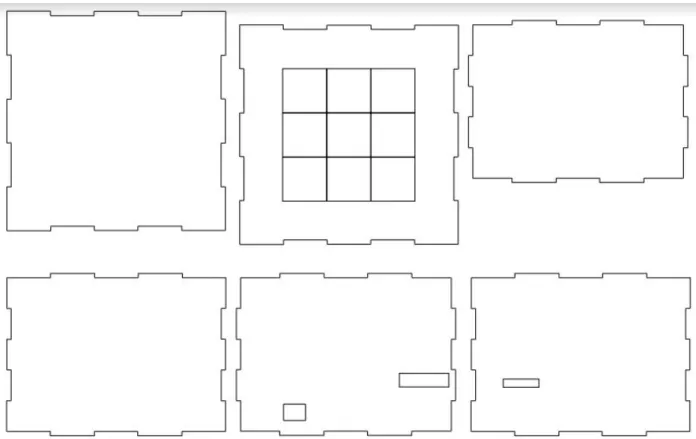
Acrylic Box
For the construction of our project, we decided to use a clear, laser cut 10”x10”x6” acrylic box for the casing to more easily debug our circuits and protect our circuit from the elements. The template for the box to be laser cut was created using Adobe Illustrator and is pictured below. Acrylic is also easy to laser cut and sturdy to hold the weight of the LEDs and wires. There are slots cut into the acrylic so it can be constructed without using adhesive, and holes for the Raspberry Pi inputs and the female to male AC adaptor.
Wiring
We used over 200 jumper cables to connect the Raspberry Pi 3, the ATmega164P PMC, Octal D Flip Flops, and LEDs. The PMC and Flip Flops are seated on two MB-102 breadboards and connected using 22 gauge leads. The system is powered by the Raspberry Pi, which is connected to the power and ground rails on the breadboards. The Raspberry Pi is connected on 9 outputs to the PMC, which is connected to each of the D Flip Flops. The outputs of the D Flip Flops are connected with 8” 20 gauge leads soldered to a 240𝛀 resistor, which is in turn soldered to the positive leg of the LED. The connection between the LED and the resistor is protected with heat shrink so as to prevent short circuiting. The LEDs are all held up to the top of the box with electrical tape, and their ground pins are all soldered together with leads and connected with one 20 gauge wire to the common ground on the breadboard.
Future Steps
Replace LEDs with Magnets
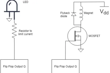
The most obvious improvement to our prototype would be to replace the LED array with a magnet array, as was originally intended. This transition would involve a redesign of how the control signals from the DFFs interact with the grid, as shown in the figure below:
Figure 12: Updating the grid from LEDs to electromagnets
This design change introduces more circuitry per point on the grid. It replaces the
current-limiting resistors with flyback diodes (both of which are used to protect the circuit from conducting too much current and damaging parts). It also adds a MOSFET and a power supply to the circuit, which is necessary because the magnets will pull much more current than the LEDs, so an external power source is needed to avoid burning out the DFFs. The MOSFETs would draw current from the same power supply that powers the digital logic components.
Full-Scale Model
The next obvious improvement would be to construct the full board. Our current prototype is a 3x3 square grid, when a real chess board is 8x8. The proposed magnet addressing scheme for the full board is shown below:
Figure 13: Magnet Address Scheme for Full-Size Board
The scheme was designed to keep the majority of the wiring symmetrical (the first 4 blocks have an identical scheme), and only having 1 block separate. Block in this diagram refers to 64
magnets controlled by a PMC and its 8 DFFs. This design has the last block control the
right/bottom edge magnets, and 8+8+6+6=28 magnets around the outside of the board. These 28 magnets would cover the perimeter of the board’s play area, placing one adjacent to each outer square. This would allow pieces to be moved off of the play area without manual intervention.
PCB
The preferred method for actually constructing our circuit is making a custom PCB with surface mount components when possible. This will clean up our circuit and reduce the need for
additional and unnecessary wires. It will save us on space and reduce the need for the acrylic box to be as tall as it is. A PCB will also let us interface easier with the Raspberry Pi and let us power the board with the power supply without burning the rails, like it would in a breadboard. Being limited to through-hole pieces hurt the bottom line for this project, and it will be cheaper and with greater selection to be able to use surface-mount components. Finally, creating a stock PCB
RFID
Adding RFID readers to the board (interfacing them with the MC) would add piece detection with custom pieces with RFID tags. This would give the MC, and the developer’s code on it, to use piece location to implement further features on the board. This is good for two reasons: Firstly, it would allow the MC to have feedback as to whether or not its commands are being performed correctly, and to self-correct and self-adjust. This would be useful for tuning (see later section).
Secondly, it would give the developer the tools to directly interact with user input. A user could move a piece on the board, and the board would be able to detect the change. A simple example of this use would be a chess game where the AI is programmed to simply copy the player’s moves.
Expanding on that, user input can be more complex. Having pieces with different behaviors create more complex interactions than would be possible otherwise. For instance, having “pieces” which act as obstacles on the board (but that can be detected) could allow players to make things like custom terrain that actively change other piece’s pathing. For instance, a maze could be physically constructed by the user using pieces with RFID tags under them, and an AI could be programmed to traverse the maze or block the user from doing so. An example of that would be a physical Pac-Man game where the user could customize the map, and the AI would randomly move within it trying to catch the user.
Network Connectivity
The motivation for using the Raspberry Pi 3 as the MC instead of another ATmel164P or some other microcontroller is the Pi’s built in networking capabilities. The Pi supports bluetooth, wifi, and ethernet. Since we installed Raspbian OS on it, developers can SSH into it to configure files, which is helpful to avoid needing a mouse/keyboard/monitor setup right next to the box. Plus, a
platform could be implemented to automatically update the Pi’s firmware.
Aside from easing the life of a developer, network capabilities offer consumers a potentially rich set of features. Players could interact with the board solely from their smartphone or tablet, or from a laptop that could have controllers set up on it. Pairing with RFID piece detection would allow the opposite interaction to occur; interacting with the board could update an application on another user’s device (like playing on a chess app but using the board as a controller).
Tunability
As mentioned in the background of the project, one major drawback of the magnet array design is that piece movement would be jerky. Adding firmware to the MC could mitigate this issue. Precision timing could be used to utilize control the magnets and see smoother movements. This is because of the physical property of electromagnets (modeled as inductors): that they cannot immediately change current but gain it over time (scaled by a calcable time constant).
The timing calculation would be very difficult, as it would need to account for piece weights and surface material (which affects friction), as well as differences in the strength of each magnet. A practical alternative would utilizing RFID tags on pieces in order to give the MC feedback about it’s piece movement. A complex initialization function could be created (and standard firmware) to calculate timings for each magnet in the grid and each piece to be used. Simply running an initialization function before a session for a couple of minutes could dramatically improve piece movement.
Appendix A
Python code to control and individual magnet #Chip Select: 5, 6, 13, 19, 26
#Address Sending: 2, 3, 4, 17, 27, 22, 10, 9 #High/low: 11
import sys
import RPi.GPIO as GPIO
from time import sleep
def setup():
GPIO.setwarnings(False)
GPIO.setmode(GPIO.BCM)
GPIO.setup(5, GPIO.OUT, initial=GPIO.LOW)
GPIO.setup(6, GPIO.OUT, initial=GPIO.LOW)
GPIO.setup(13, GPIO.OUT, initial=GPIO.LOW)
GPIO.setup(19, GPIO.OUT, initial=GPIO.LOW)
GPIO.setup(26, GPIO.OUT, initial=GPIO.LOW)
GPIO.setup(2, GPIO.OUT, initial=GPIO.LOW)
GPIO.setup(3, GPIO.OUT, initial=GPIO.LOW)
GPIO.setup(4, GPIO.OUT, initial=GPIO.LOW)
GPIO.setup(17, GPIO.OUT, initial=GPIO.LOW)
GPIO.setup(27, GPIO.OUT, initial=GPIO.LOW)
GPIO.setup(22, GPIO.OUT, initial=GPIO.LOW)
GPIO.setup(10, GPIO.OUT, initial=GPIO.LOW)
GPIO.setup(9, GPIO.OUT, initial=GPIO.LOW)
GPIO.setup(11, GPIO.OUT, initial=GPIO.LOW)
def cleanup():
GPIO.output(2, 0)
GPIO.output(3, 0)
GPIO.output(4, 0)
GPIO.output(27, 0) GPIO.output(22, 0) GPIO.output(10, 0) GPIO.output(9, 0) GPIO.output(11, 0) GPIO.output(5, 0) GPIO.output(6, 0) GPIO.output(13, 0) GPIO.output(19, 0) GPIO.output(26, 0) GPIO.cleanup()
def send_data(address, state): #address = int(address) cs = 0 if(address < 0x40): cs = 5 elif(address < 0x80): cs = 6 address = address - 0x40 elif(address < 0xC0): cs = 13 address = address - 0x80 elif(address < 0x100): cs = 19 address = address - 0xC0 elif(address < 0x140): cs = 26 address = address - 0x100 GPIO.output(11, state)
GPIO.output(2, address & 0x01)
GPIO.output(3, (address >> 1) & 0x01)
GPIO.output(4, (address >> 2) & 0x01)
GPIO.output(17,(address >> 3) & 0x01)
GPIO.output(27,(address >> 4) & 0x01)
GPIO.output(10,(address >> 6) & 0x01)
GPIO.output(9, (address >> 7) & 0x01)
#GPIO.output(2, address & 0x01) #GPIO.output(3, address & 0x02) #GPIO.output(4, address & 0x04) #GPIO.output(17,address & 0x08) #GPIO.output(27,address & 0x10) #GPIO.output(22,address & 0x20) #GPIO.output(10,address & 0x40) #GPIO.output(9, address & 0x80)
GPIO.output(cs, 1)
sleep(.1)
GPIO.output(cs, 0)
def send_array(address_arr, state):
for address in address_arr:
send_data(address, state) sleep(0.1) def send_all(): for i in range(49): send_data(i, 1) sleep(.5) send_data(i, 0)
def send_all(delay=None):
if delay == None: delay = .1 else: delay = max(delay, .1) for i in range(49): send_data(i, 1) sleep(delay) send_data(i, 0)
def translate(row, column):
if(row % 2 == 0):
return (row*7 + column)
else:
return(row*7 + (6-column))
def main(): setup() #send_data(translate(int(sys.argv[1]), int(sys.argv[2])), int(sys.argv[3])) send_all(.01) sleep(1) cleanup() if __name__ == "__main__": main()
Appendix B
Python Code (framework only - not yet implemented)
import send_board
board = []
class Magnet:
def __init__(self, addr, state, neighbors = None):
self.addr = addr self.state = state if(neighbors != None): self.tl = neighbors[0] self.t = neighbors[1] self.tr = neighbors[2] self.l = neighbors[3] self.r = neighbors[4] self.bl = neighbors[5] self.b = neighbors[6] self.br = neighbors[7] class Square:
def __init__(self, is_piece, is_corner, is_edge, name, row, col,
magnets = None, neighbors = None): self.is_piece = is_piece self.is_corner = is_corner self.is_edge = is_edge self.name = name self.row = row self.col = col if(magnets != None): self.tl = magnets[0] self.t = magnets[1] self.tr = magnets[2] self.l = magnets[3] self.c = magnets[4] self.r = magnets[5] self.bl = magnets[6] self.b = magnets[7] self.br = magnets[8]
if(neighbors != None): self.tl = neighbors[0] self.t = neighbors[1] self.tr = neighbors[2] self.l = neighbors[3] self.r = neighbors[4] self.bl = neighbors[5] self.b = neighbors[6] self.br = neighbors[7]
def populate(length, width):
letters = ["a", "b", "c", "d", "e", "f", "g", "h"] count = 0
for i in range(length):
for j in range(width):
board[count] = Square(False, False, False, letters[j] + str(i+1), i+1, letters[j])
count += 1 for sq in board:
if(sq.row == 1 || sq.row == length || sq.col == a || sq.col == letters[width-1]):
sq.is_edge = True
if(sq.row == 1 && sq.col == a || sq.row == 1 && sq.col == letters[width-1] || sq.row == length && sq.col == a || sq.row == length && sq.col == letters[width-1]):
sq.is_corner = True if
Appendix C
C code (MAIN) to run PMC /** Author: Kyle King
* Senior Project 2019 - California Polytechnic State University *
* Datasheet Referenced for programming: *
http://ww1.microchip.com/downloads/en/DeviceDoc/ATmega164P-324P-644P-Data-S heet-40002071A.pdf
*
* Program Description:
* Use the Atmel164P as a controller for 8 Octal Data Flip Flops.
* Operation of the Atmel chip is as follows:
* Input CS (bit) goes HIGH:
* --> then sample inputs MAGVAL (bit) and MAGADDR (8-bit
bus)
* --> Updates locally held DFF values in the 'dffs' array
* Output Timer triggers:
* --> put current dff on output MAGOUT (8-bit bus)
* --> update DFFCLK (8-bit bus) to select current DFF for
data transfer
* --> update current dff to be next dff
*/
#include "PMC.h" #ifndef F_CPU
#define F_CPU 1000000UL #endif
#include "util/delay.h" //can't use unless comment out TIMER_INIT() in
pmc.c
/* === NOTES === */
//"Device Programming" <Ctrl+Shift+P> -> "Apply" -> Fuses -> LOW.CKDIV8 --> Uncheck... is how you dont /8.
//#include <util/delay.h> //for software delays
//F_CPU defines clk freq so delay recognizes it. 1000000UL == 1MHz /* === TODO === */
//Figure out difference between PORT and PIN and make code work with that //rewrite the updateDFFs function to be bulkier but faster.
//Try using the sleep() function (SLEEP_MODE_IDLE?) /* === DECLARATIONS === */
//I'm declaring PB2 to be an LED used for debugging during the development process
#define LED_P3 BIT2 #define LED_P4 BIT3 #define LED_PORT PORTB #define LED_PORT_DIR DDRB /* === GLOBAL VARIABLES === */
uint8_t dffs[8] = {0x00,0x00,0x00,0x00,0x00,0x00,0x00,0x00};
uint8_t currentDFF=0;
/* === MAIN === */
int main(void)
{
/* for debugging
LED_PORT_DIR = setGPIO(LED_PORT_DIR, LED_P3 | LED_P4, GPIO_SET_OUTPUT);
//LED_PORT = (LED_PORT | LED_P3) & ~LED_P4; LED_PORT &= ~LED_P3;
LED_PORT |= LED_P4; */ init_PMC(); /*testing only dffs[7]=BIT1; dffs[6]=BIT1; dffs[5]=BIT1; dffs[4]=BIT1; dffs[3]=BIT1; dffs[2]=BIT1; dffs[1]=BIT1;
/* RUN (forever) */ while(1) { } return 0; }
/* === TIMER 1 (16-bit) ISR === */
ISR(TIMER1_COMPA_vect) { sendToDFF(currentDFF, dffs); currentDFF = currentDFF+1; if(currentDFF>=8) { currentDFF=0; }
//no interrupt flag clearing necessary
}
/* === CS PIN ISR ('PB0' --> PCINT8) === */
ISR(PCINT1_vect) {
uint8_t val, addr;
if(CS_READ_BUS & CS) //caught a rising edge
{
val = (MAGVAL_READ_BUS & MAGVAL) ? 1 : 0; //update the magnet state
addr = MAGADDR_READ_BUS;
updateDFFarray(val, addr, dffs); }
//no interrupt flag clearing necessary
Appendix D
C Code (PMC Header) #ifndef PMC_H#define PMC_H #include <avr/io.h>
//on my machine, the file this references is //C:\Program Files
(x86)\Atmel\Studio\7.0\packs\atmel\ATmega_DFP\1.2.209\include\avr\iomxx4.h #include <avr/interrupt.h>
//for the Timer and GPIO interrupts #include <stdio.h>
#include <stdint.h> #include <stdlib.h>
//generic bit values for bitwise operations. #define BIT0 0x01 #define BIT1 0x02 #define BIT2 0x04 #define BIT3 0x08 #define BIT4 0x10 #define BIT5 0x20 #define BIT6 0x40 #define BIT7 0x80 #define ON 1 #define OFF 0 //GPIO state #define GPIO_SET_OUTPUT 1 #define GPIO_SET_INPUT 0
//define our 10 input pins on Ports A and B #define CS BIT0
#define MAGADDR_0 BIT0 #define MAGADDR_1 BIT1 #define MAGADDR_2 BIT2 #define MAGADDR_3 BIT3 #define MAGADDR_4 BIT4 #define MAGADDR_5 BIT5 #define MAGADDR_6 BIT6 #define MAGADDR_7 BIT7
#define CS_WRITE_BUS PORTC #define CS_READ_BUS PINC #define MAGVAL_WRITE_BUS PORTC #define MAGVAL_READ_BUS PINC #define MAGADDR_WRITE_BUS PORTA #define MAGADDR_READ_BUS PINA #define CS_DIR DDRC #define MAGVAL_DIR DDRC #define MAGADDR_DIR DDRA
//define our 16 output pins on ports C and D #define MAGOUT_0 BIT0
#define MAGOUT_1 BIT1 #define MAGOUT_2 BIT2 #define MAGOUT_3 BIT3 #define MAGOUT_4 BIT4 #define MAGOUT_5 BIT5 #define MAGOUT_6 BIT6 #define MAGOUT_7 BIT7 #define DFFSEL_0 BIT0 #define DFFSEL_1 BIT1 #define DFFSEL_2 BIT2 #define DFFSEL_3 BIT3 #define DFFSEL_4 BIT4 #define DFFSEL_5 BIT5 #define DFFSEL_6 BIT6 #define DFFSEL_7 BIT7
#define MAGOUT_WRITE_BUS PORTD #define MAGOUT_READ_BUS PIND
#define DFFSEL_READ_BUS PINB #define MAGOUT_DIR DDRD #define DFFSEL_DIR DDRB
/* --- Now for functions declarations --- */
uint8_t setGPIO(uint8_t bus, uint8_t pinVal, uint8_t mode);
void init_PMC();
void Timer1A_init(uint16_t top);
void updateDFFarray(uint8_t val, uint8_t addr, uint8_t * dffs);
void sendToDFF(uint8_t currentOutput, uint8_t * dffs);
Appendix E
C code (PMC C file) #include "PMC.h"void init_PMC()
{
WDTCSR &= ~WDE; //turn off Watchdog Timer
//Init INPUTs
CS_DIR = setGPIO(CS_DIR, CS, GPIO_SET_INPUT); MAGVAL_DIR = setGPIO(MAGVAL_DIR, MAGVAL, GPIO_SET_INPUT); MAGADDR_DIR = setGPIO(MAGADDR_DIR, MAGADDR_0, GPIO_SET_INPUT); CS_WRITE_BUS &= ~CS; //don't enable pull-up resistor
MAGVAL_WRITE_BUS &= ~MAGVAL; //don't enable pull-up resistor
/*testing only
CS_DIR = setGPIO(CS_DIR, CS, GPIO_SET_OUTPUT); MAGVAL_DIR = setGPIO(MAGVAL_DIR, MAGVAL, GPIO_SET_OUTPUT); MAGADDR_DIR = setGPIO(MAGADDR_DIR, MAGADDR_0, GPIO_SET_OUTPUT); CS_WRITE_BUS &= ~CS; //off
MAGVAL_WRITE_BUS &= ~MAGVAL; //magnet off MAGADDR_WRITE_BUS = 0; //address 0 */ //Init OUTPUTs DFFSEL_DIR = setGPIO(DFFSEL_DIR, (DFFSEL_0|DFFSEL_1|DFFSEL_2|DFFSEL_3|DFFSEL_4|DFFSEL_5|DFFSEL_6|DFFSEL_7), GPIO_SET_OUTPUT); MAGOUT_DIR = setGPIO(MAGOUT_DIR, (MAGOUT_0|MAGOUT_1|MAGOUT_2|MAGOUT_3|MAGOUT_4|MAGOUT_5|MAGOUT_6|MAGOUT_7), GPIO_SET_OUTPUT); //DFFSEL_DIR=0xFF; //MAGOUT_DIR=0xFF;
// INTERRUPT for CS pin
//CS is PortB, bit0. This is PCINT8
PCMSK1 = 0x01; //PCMSK = PCINT15 PCINT14 PCINT13 PCINT12 PCINT11 PCINT10 PCINT9 PCINT8 . PCINT8 is the one we need high.
PCICR = 0x02; //PCICR = 0 0 0 0 PCIE3 PCIE2 PCIE1 PCIE0 . PCINT8 needs PCIE1 to be high.
//set all DFFs to zeros
MAGOUT_WRITE_BUS = 0; //set all DFF outputs to zero
DFFSEL_WRITE_BUS = 0xFF; //enable every DFF to read from input
DFFSEL_WRITE_BUS = 0x00; //deselect DFFs after ~1us (since system clock is 1MHz)
Timer1A_init(12500); //12500 == 12.5ms since function inits Timer1 to run at 1Mz.
//Also Timer1 is the 16bit timer, so this value is valid.
sei(); //enable interrupts so the timer functions correctly (also other interrupts, like the CS GPIO input pin.
}
void Timer1A_init(uint16_t top)
{
//TODO:
//What do we need to set?
//TCCRxx, TIMSKx, OCRxx, OCRxxH, OCRxxL.
//we want CTC - UP Mode (clear timer on compare) = b100 //so WGM should be 0b0100
//desc: COM stuff @ zero sets no timer output pins, WGM sets lower WGM bits
//TCCR1A = COM1A1 | COM1A0 | COM1B1 | COM1B0 | - | - | WGM11 | WGM10
TCCR1A = 0x00 | 0x00; //no output pins set up, WGM == xx00
//desc: IC stuff deals with capture noise. WGM sets upper WGM bits. CS is clock div, where 001 means div/1.
//TCCR1B = 01 0 01 001; == 0b01001001 == 0x49
TCCR1B = 0x49;
//desc: FOC stuff used when non-PWM (so, our case), just forces a comparison on the timer... nah
//TCCR1C = FOC1A FOC1B
-TCCR1C = 0;
//desc: IC capture IE, nty. OC compare IE, yesplz. TOIE, overflow IE, nah.
//TIMSK1 = - - ICIE1 - - OCIE1B OCIE1A TOIE1
TIMSK1= 0x02; //only 'Output Compare A Match Interrupt' Enabled //desc: the value to compare against, 16bits split into 2regs
OCR1AH= (top & 0xFF00) >> 8; OCR1AL= top & 0x00FF;
//TIFR
//This is the interrupt flag register for timer 1. Its values are auto-cleared.
}
//val is ON/OFF, addr is digital number, 0-63. Dividing into 8 8-bit values that represent pins.
void updateDFFarray(uint8_t val, uint8_t addr, uint8_t * dffs)
{
/* no this isn't as efficient as 16 if statements but I'm lazy */
uint8_t whichDFF = addr/8;
uint8_t whichBit = 1 << (addr % 8);
if(val==0) {
dffs[ whichDFF ] &= ~whichBit; } else { dffs[ whichDFF ] |= whichBit; } }
void sendToDFF(uint8_t currentDFF, uint8_t * dffs) {
DFFSEL_WRITE_BUS = 0; //just in case it was left on somewhere
MAGOUT_WRITE_BUS = dffs[currentDFF]; //load the 8 magnet values onto the pins
DFFSEL_WRITE_BUS = (1 << currentDFF); //enable the target DFF to take input
DFFSEL_WRITE_BUS = 0;
//MAGOUT_WRITE_BUS = dffs[0]; //load the 8 magnet values onto the pins
//DFFSEL_WRITE_BUS = DFFSEL_0; //enable the target DFF to take input //DFFSEL_WRITE_BUS = 0; //disable
//MAGOUT_WRITE_BUS &= ~BIT2;
//DFFSEL_WRITE_BUS = DFFSEL_0; //send it //DFFSEL_WRITE_BUS = 0; //release it
}
/* Bus will be the read in value of DDRx, which is read/write (per the datasheet.) */
uint8_t setGPIO(uint8_t bus, uint8_t pinVal, uint8_t mode)
{
if(mode==GPIO_SET_INPUT) {
return bus & ~pinVal;
}
else if(mode==GPIO_SET_OUTPUT) {
return bus | pinVal;
} else { //exit(1); return bus; } }