A model for documenting architectural decisions
María Luciana Roldán, Silvio Gonnet, and Horacio Leone
INGAR (UTN-CONICET), Facultad Regional Santa Fe Universidad Tecnológica Nacional
Santa Fe, Argentina
{lroldan, sgonnet, hleone}@santafe-conicet.gov.ar
Abstract. A software architecture is the result of architectural design decisions. Documenting a software architecture should not only describe the final model, but also why the architecture looks as it does. During the software architecture design process, several decisions are made, which need to be captured and doc-umented in a systematic way to prevent knowledge vaporization and high archi-tecture’ costs of change. In this work, a model for capturing, documenting and recovering architectural design processes and their underlying design rationale is proposed. The design process is envisioned under an operational perspective, where design decisions are represented as sequences of operations. Besides, the model is extensible to manage several design products types from different do-mains and views, including aspects of architectural rationale. Complementary, the proposal provides a semi-automatic mechanism for generating architectural rationale documents based on the use of templates.
Keywords: architecture documentation, design rationale, design decisions
1
Introduction
Software architecture design process (SADP) comprises the early decisions to achieve the quality and functional requirements and constraints of a complex system [1]. Tra-ditionally, software architectures have been described from structural and behavioral points of view as a set of interconnected software components. However, in the last years there has been a shift towards regarding software architecture as the composi-tion of a set of architectural decisions and their racomposi-tionale [2, 3, 4, 5]. Kruchten et al. [6] have joined these two dimensions of software architecture in the concept of tectural Knowledge (AK), providing the formula: AK = Architectural Design + Archi-tectural Decisions.
Designers, architects and other stakeholders have recognized the importance of documenting design decisions and rationale, and not only capturing the final architec-tural artifact but also the design decisions that generated it [7]. However, surveys have revealed difficulties in capturing and exploiting the design rationale: the practice of documenting AK has not been widely spread and adopted due to some inhibitors, such as the overhead imposed on the designer due to the required documentation ef-fort. In practice, AK documentation is considered a resource-intensive process
with-out tangible (short-term) gains for the documenters themselves, reason why is often skipped or performed inadequately [8]. Documenting AK is traditionally considered an activity supplementary to architecting, thus typically, someone documents what the architect has decided after-the-fact [9].
Consequently, there is an imminent necessity of enhancing the architecting process with effective ways of AK documentation. We propose a model that captures each decision made in a SADP along with their resulting products and the rationale that supports them, and makes possible the tracing of the history of the design process. The model is extensible to permit working with several domains and representing software architecture models with elements from different architectural views, includ-ing reasoninclud-ing aspects. To get higher benefits from the captured design decisions and their results, a mechanism for semi-automatically architectural rationale documenta-tion is proposed.
The rest of the paper is structured as follows. In Section 2, the model for capturing and tracing SADP is described. Furthermore, we define a general software architec-tures domain, which includes design object types and operations relative to design rationale. Next, in Section 3, we propose a mechanism to automatically documenting design rationale. In section 4, a case study is developed to illustrate the proposed ap-proach. Finally, in the last section, we compare this approach to related work and share some conclusions.
2
A model for capturing and tracing SADP
The proposed model is envisioned under an operational perspective, where design decisions are materialized as the execution of design operations, which are applicable to specific design object types. This scheme considers the SADP as a series of design decisions that transforms the products (or design objects) of the design process. Typi-cal design objects are the structural elements of the artifact that is being designed (i.e. the components and connectors that comprise a software architecture), and the specifi-cations to be met (i.e. quality requirements such as modifiability or performance). Nat-urally, these objects evolve as the SADP takes place, giving rise to several versions that participate in several model versions. A model version describes the state of the design process at a given point in the design process.
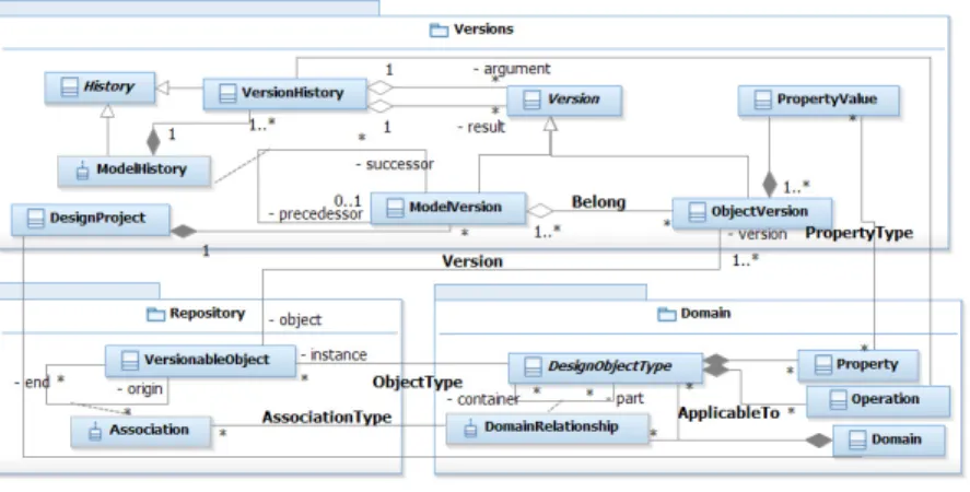
The capabilities of the proposed model for saving SADP design decisions are based upon a versioning scheme (Fig. 1) that capture all the executed operations and generated design objects. That versioning scheme has the necessary elements for rep-resenting the evolution of design objects during an architectural design project. De-sign objects are represented at two levels, the repository and the versions’ level. The repository level keeps a unique entity for each design object that has been created and/or modified during a design project. This object is called versionable object. As-sociations among the different versionable objects are hold in the repository to repre-sent the configuration of the architectural model (Association, Fig. 1). The versions’ level keeps the different versions of each design object, which are called object ver-sions. The relationship between a versionable object and its object versions is repre-sented by the version association.
Fig. 1. Versioning scheme
Therefore, a design object keeps a unique instance in the repository and all the
ver-sions it assumes in different model verver-sions belong to the verver-sions’ layer. Under this operational perspective, the evolution of an architectural model is posed as a history made up of discrete situations, where a new model version is generated by applying a sequence of operations (φ) on a predecessor model version, which generates a succes-sor model version.
Domain Package (Fig. 1) enables defining the types of design objects, whose
in-stances are going to be maintained in a given SADP. Design object types represent
concepts of a domain and have properties specified by a set of instances of Property class. The possible relationships among the different design object types of a domain
are instantiated from DomainRelationship class. Particularly, associations between
design objects at repository level are instances of a given type of domain relationship.
In this approach, each sequence of operations is applied to a model version to
transform it in a new model version. The sequence of operations is captured by means of a model history link, and each executed operation is represented by a version his-tory link that keeps references among the object versions on which the operation was applied and the ones arising as a result of its execution. As it is shown in Fig. 1, a ModelHistory link aggregates various VersionHistory links, one for each operation in the sequence of operations.
Before starting a design process, an expert defines a domain or selects an existent one. Since there is no universal architectural design language, it is not possible to establish an “a priori” domain model covering all the possible information items, work processes, and relations that may be applicable in different design projects and situations. Therefore, the domain model is adapted to each particular design problem, including concepts suitable for the employed design method, the preferred approach for representing architectural views, the chosen design language, and the system do-main. In a previous work [10], a conceptual software architecture domain model was proposed, regarding several concepts taken from the Attribute Driven Design method [1] for designing architectures. This method follows an iterative decomposition and proposes describing an architecture by means of several views [11]. Views are a
rep-resentation of the system from a perspective of a related set of concerns, called view-type. Therefore, a viewtype is a specification of the conventions for constructing and using a view, thus it determines the languages to be used to describe a view, and any associated modelling methods or analysis techniques to be applied to the representa-tion of the view. The concept of viewtypes (but named viewpoints) is also regarded by the IEEE 1471 Standard the architectural description of software-intensive systems [12]. Examples are Module, Component-and-Connector and Allocation.
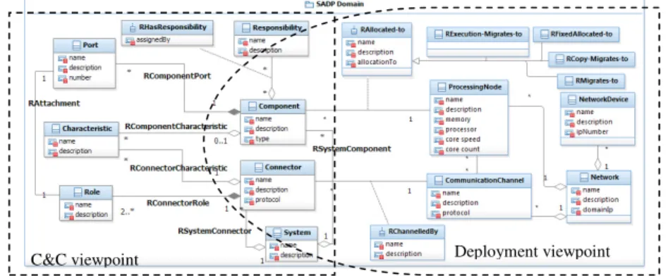
A possible SADP domain is presented in Fig. 2, which comprises elements from Components-and-Connector (C&C) and Allocation viewpoint. C&C viewpoint mainly focuses in the division of responsibilities and behaviour of the components of a software architecture and how they are interrelated. Design object types that are
included are Component, Connector, Port, Role and Attachment. Characteristic and
Responsibility design object types are included to represent some relevant properties
and the behaviour of components and connectors. RHasResponsibility is a domain
relationship that represents a link between a responsibility and the component. RHasResponsibility has been reified as a design object type to enabling defining
properties like assignedBy property, to represent who is the actor responsible of
as-signing or delegating a responsibility to a component. The domain under definition
can be extended with concepts from Deployment viewpoint, a kind of Allocation
view, which is useful for describing how software elements of a software architecture interact with non-software elements in the environment in which the software is de-ployed or executed, like ProcessingNode and Network [10].
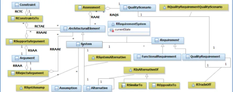
The flexibility of the model allows us to define design object types for representing architectural design rationale (Fig. 3). These new elements are associated to other design object types relative to structure, behaviour and deployment of the software architecture model (ArchitecturalElement abstract design object type, in Fig. 3). A first set of design object types to support design rationale is also derived from some aspects of ADD method. ADD is based on a decomposition process, where architec-tural patterns are chosen to fulfill certain requirements. The inputs to ADD are quality requirements that are expressed as a set of system specific quality scenarios, func-tional requirements that are translated into a set of responsibilities that are assigned to components, and constraints.
Fig. 2. Partial SADP domain with elements of C&C and Deployment viewpoints
ADD prescribes that at the end of an iteration, designers should assess the level of
achievement of the architectural model to a given quality scenario (how close is the
architecture model of achieving a requirement). For that reason Assessment design
object is included as a domain concept. Also, Constraint type explicitly represents
rules or conditions imposed on the architecture model, as well as Assumption design object type represents something that is taken for granted in the design process.
Other concepts included in the domain to represent design rationale are:
Alterna-tive, to represent possible directions in which the architecture of the intended system could be obtained, and Argument, useful for expressing the reasons that are advanced-for or against-to an alternative.
Design object types for rationale enables a designer to make explicit certain knowledge for explaining or rationalising an architectural model. In this way, explicit rationale object versions (such as requirements, assumptions, and arguments) can be added to the software architecture model and be associated to other architectural ele-ments (like behavioural or structural versions). Therefore, SADP domain also in-cludes suitable domain relationships to link architectural model elements and ration-ale elements. Examples of reified domain relationships are RRegardsAssumption and RConstraintsTo. RTradeOff is useful to express the existence of a trade-off between two quality requirements (when the achievement of one quality requirement is in detriment of the achievement of another, and vice versa). Moreover, RSupportsArgu-ment and RRejectsArguRSupportsArgu-ment enable associating a set of architectural eleRSupportsArgu-ments and the argument that justifies or rejects the presence of those elements in a given architec-tural model. Other relationships in the domain are RSystemAlternative, ROppossiteTo, and RSimilarTo, whose meaning is quite intuitive from Fig. 3.
To explicitly represent designer’s intentions in a model version, suitable design object types can be included in the domain (Fig. 4). RPossibleScenarioSolution
associ-ates a quality scenario and architectural elements that are the results of an operation,
indicating that the pursued goal of that operation is a given quality scenario. Similarly, RConsidersConstraint enables expressing that an architectural design (or a portion of it) fits to a particular constraint that is imposed on the system.
As it was introduced, domain operations are intended to transform the design prod-ucts of a SADP, thus generating new versions, modifying or eliminating other ones. To transform model versions, the scheme provides a set of primitive operations: add, de-lete, and modify (specializations of Operation class, in Domain package of Fig. 1).
Fig. 4. Design object types to support designer intentions
By using the add operation, an object version that did not exist in a previous model
version can be incorporated into a successor model version. Conversely, the delete
operation eliminates an object version that existed in the previous model version. In
addition, the modify operation creates a new version of a given version of a design
object. When a sequence of operations is applied on a model version, a new model version is generated and an architectural design decision is materialized. Since
primi-tives add, delete and modify are not enough to represent adequately high level design
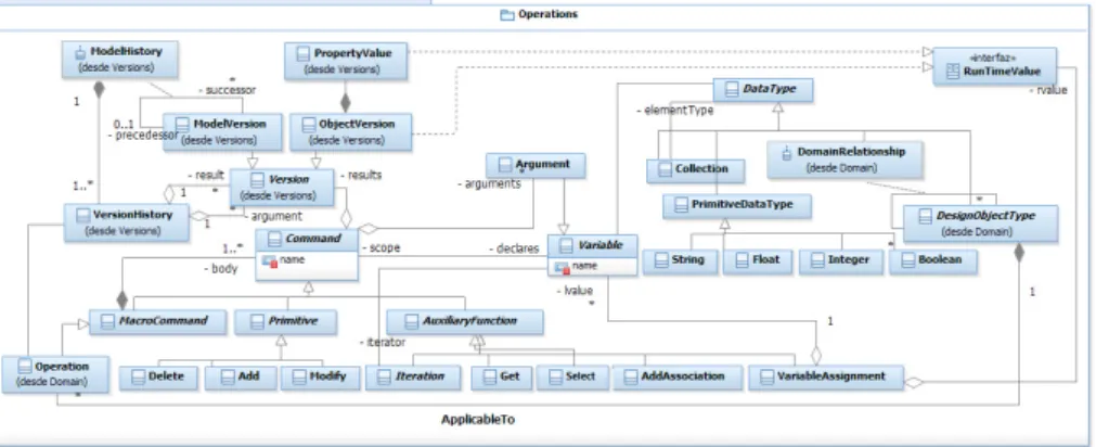
decisions, it is necessary to provide the model with capabilities for defining and exe-cuting complex operations for the SADP domain, which is provided by the elements of Operations package (Fig. 5). The central class in Operations package is the command abstract class. An operation is defined as a macrocommand, which is a command that executes a sequence of commands and can be applied to a specific design object type (ApplicableTo association). On the one hand, an operation requires defining its input arguments. DataType abstract class generalises the types of arguments supported by the model. On the other hand, an operation requires a list of subcommands that forms its body. The body can be primitives, auxiliary functions, and other operations from the
same domain. Auxiliary functions are pre-built functions like Iteration,
VariableAs-signment, recovering and selection of elements (Get and Select), etc. AddAssociation is a function to set associations between versionable objects at repository level. To make possible the execution of operations, the operations model is integrated to the version-ing scheme (Fig. 1) that provides the elements for capturversion-ing the execution of sequences of operations. Each particular operation executed in the sequence is captured by a
his-tory link (VersionHishis-tory), which also keeps the argument values and the resulting
versions (result). A model history link may also save information like date/time when the sequence was executed and the actor who made the decision.
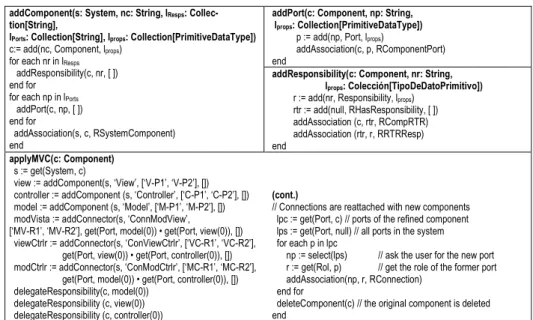
By instantiating the Operations model, a set of operations can be defined for manipu-lating design object types. The model is flexible for defining operations with different abstraction level, so they can be as basic as addComponent, or as complex as the erations that apply an architectural pattern or a tactic [1]. Fig. 6 shows some basic op-erations. The body of each operation is defined in terms of primitive operations like add(np, Port, lprops) in addPort operation, and non-primitive ones, like addPort(c, np, []) in addComponent. The header of an operation indicates its name and its required
arguments and types (enclosed in brackets). For example, the arguments of
addCom-ponent operation are: s (the system in which the comaddCom-ponent is going to be added), nc
(the name of the component to add), lResps (a collection with the names of the
responsi-bilities of the component), lPorts (a collection with the names of the ports of the
compo-nent), and lProps (a collection with the values of the properties of the component). The
operation incorporates a component c to a system. Then a set of responsibilities (lResps)
and ports (lPorts) are inserted using an iteration, which is syntactically expressed by
means of “for each … in …” sentence. Finally, resulting design objects are associated at repository level in correspondence with the rules of domain relationships, by means of the auxiliary function addAssociation.
Architectural design patterns are more complex and higher level operations, as they
represent well known and recurring design solutions. In Fig. 6, applyMVC operation
encloses the knowledge of MVC pattern. The operation generates a topological
con-figuration that fits to the MVC architectural pattern. The new architectural elements are: View, Model, and Controller components, their ports (‘V-P1’ and ‘V-P2’ for View; ‘M-P1’ and ‘M-P2’ for Model; and ‘C-P1’ and ‘C-P2’ for Controller), and the connec-tors between them (‘ConnModView’, ‘ConViewCtrlr’, and ‘ConModCtrlr’) with their respective roles. Since the original component (c argument) is refined by the operation, its responsibilities must be delegated to the new components (delegateResponsibility operation). In addition, Get and Select auxiliary functions are used.
addComponent(s: System, nc: String, lResps:
Collec-tion[String],
lPorts: Collection[String], lprops: Collection[PrimitiveDataType])
c:= add(nc, Component, lprops)
for each nr in lResps
addResponsibility(c, nr, [ ]) end for
for each np in lPorts
addPort(c, np, [ ]) end for
addAssociation(s, c, RSystemComponent) end
addPort(c: Component, np: String, lprops: Collection[PrimitiveDataType])
p := add(np, Port, lprops)
addAssociation(c, p, RComponentPort) end
addResponsibility(c: Component, nr: String, lprops: Colección[TipoDeDatoPrimitivo])
r := add(nr, Responsibility, lprops)
rtr := add(null, RHasResponsibility, [ ]) addAssociation (c, rtr, RCompRTR) addAssociation (rtr, r, RRTRResp) end applyMVC(c: Component) s := get(System, c)
view := addComponent(s, ‘View’, [‘V-P1’, ‘V-P2’], []) controller := addComponent (s, ‘Controller’, [‘C-P1’, ‘C-P2’], []) model := addComponent (s, ‘Model’, [‘M-P1’, ‘M-P2’], []) modVista := addConnector(s, ‘ConnModView’,
[‘MV-R1’, ‘MV-R2’], get(Port, model(0)) • get(Port, view(0)), []) viewCtrlr := addConnector(s, ‘ConViewCtrlr’, [‘VC-R1’, ‘VC-R2’],
get(Port, view(0)) • get(Port, controller(0)), []) modCtrlr := addConnector(s, ‘ConModCtrlr’, [‘MC-R1’, ‘MC-R2’],
get(Port, model(0)) • get(Port, controller(0)), []) delegateResponsibility(c, model(0))
delegateResponsibility (c, view(0)) delegateResponsibility (c, controller(0))
(cont.)
// Connections are reattached with new components lpc := get(Port, c) // ports of the refined component lps := get(Port, null) // all ports in the system for each p in lpc
np := select(lps) // ask the user for the new port
r := get(Rol, p) // get the role of the former port
addAssociation(np, r, RConnection) end for
deleteComponent(c) // the original component is deleted end
Since we count with design rationale related types, the SADP domain can be extended with operations to make explicit certain designer’s intentions and supporting rationale information (Fig. 7). A straightforward way of capturing intentions is defining opera-tions with an additional argument for indicating the goal the architect is trying to achieve at the moment of executing them. The effective value of a goal argument can be a quality requirement to be satisfied, a scenario to be approached, a constraint to be
considered, an assumption to be regarded, etc. In this way, the previously defined
de-sign operations (Fig. 6) can be specified regarding the goal to be reached. For example, applyMVC-go operation (Fig. 7) aims to achieve a given quality requirement. In the
operation specification that is expressed by associating the resulting versions of
ap-plyMVC execution with a selected scenario of the intended requirement (goal), by means of assignPossibleScenarioSolution operation. Additionally, deleteConnector-go operation (Fig. 7) enables capturing the knowledge for expressing that the argument connector (c) is eliminated because the constraint (g) has been considered.
3
Mechanism for Documenting Architectural Rationale
In this section, a complementary documentation mechanism is proposed, which organ-izes the captured knowledge in a structured document. This mechanism considers an applied “sequence of operations” as an “architectural design decision”, which is
cap-tured by a model history link. The mechanism consists on: i) generating an
architec-tural rationale (AR) object from the captures of the model evolution each time a
de-sign decision is made, and ii) attaching that AR object to the model history link that
captured the applied sequence of operations.
AR objects are instances of ArchitecturalRationale class, which is related to
ModelHistory class with a one-to-one association (Explains association, in Fig. 8). An AR object can be considered as a structure formed by several fields, in which each field keeps some information about a particular item. The format of such object is inspired on various templates for documenting decisions and rationale about software architectures [2, 4]. These templates have a fixed number of mandatory fields that should be filled, but our proposal enables tailoring the items of the template to the documenting needs of the specific project. Examples of items of an AR object are: “elicited requirements for a system”, “pursued scenarios”, “imposed constraints”, “arguments in favour of the decision”, and “arguments against the decision”.
applyMVC-go(c: Component, g: QualityRequirement)
lres := applyMVC(c) ls := select(get(Scenario, g)) for each s in ls
assignPossibleScenarioSolution (s, null, lres) end for
end
deleteConnector-go(c: Connector, g: Constraint)
s := get(System, c) deleteConnector(c)
considersConstraint(null, g, [s], []) end
assignPossibleScenarioSolution(npss: String, sce: Quality-Scenario, versionsList: [ArchitecturalElement])
pss := add(npss, RPossibleScenarioSolution) addAssociation(sce, pss, RPSSQS)
(cont.)
for each v in versionsList addAssociation(pss, v, RPSSAE) end for
end
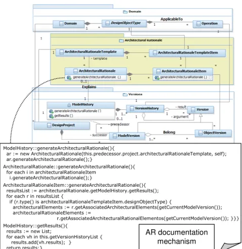
Fig. 8. Architecture rationale documentation model
An AR template is constituted by different AR template items (represented in Fig. 8 by
the aggregation between ArchitecturalRationaleTemplate and
ArchitecturalRation-aleTemplateItem classes). Each AR template item is associated to a given design ob-ject type to indicate the type of obob-ject versions that will provide the necessary infor-mation to fill that item. When starting a new SADP project, the documenting
prefer-ences for each model evolution should be defined by instantiating
ArchitecturalRa-tionaleTemplate.
Fig. 8 also presents the mechanism for generating architectural rationale objects, which is implemented as the method generateArchitecturalRationale of ModelHistory
class. The first step of ModelHistory::generateArchitecturalRationale method is
con-structing an empty instance of ArchitecturalRationale (ar) based on the template that
has been defined for the current project (new operation). Then, the ar object is linked to the model history that represents the model evolution (self in generateArchitectural-Rationale method). The following action is obtaining the information to fill in each item of the AR object (ArchitecturalRationale::generateArchitecturalRationale method), which delegates to the items the responsibility of obtaining the pertaining
ModelHistory::generateArchitecturalRationale(){
ar := new ArchitecturalRationale(this.predecessor.project.architecturalRationaleTemplate, self); ar.generateArchitecturalRationale();}
ArchitecturalRationale::generateArchitecturalRationale(){ for each i in architecturalRationaleItem
i.generateArchitecturalRationale();}
ArchitecturalRationaleItem::generateArchitecturalRationale(){ resultsList := architecturalRationale.getModelHistory.getResults(); for each r in resultsList {
if (r.type() is architecturalRationaleTemplateItem.designObjectType) {
architecturalElements := r.getAssociatedArchitecturalElements(getCurrentModelVersion()); architecturalRationaleElements :=
r.getAssociatedArchitecturalRationalElementos(getCurrentModelVersion()); }}} ModelHistory::getResults(){
results := new List;
for each vh in this.getVersionHistoryList { results.add(vh.results); }
return results;}
AR documentation mechanism
information for filling in itself. Thus, each item performs ArchitecturalRationaleItem::
generateArchitecturalRationale method.
ArchitecturalRationale-Item::generateArchitecturalRationale method, shown in the pseudocode of Fig. 8 is repeatedly executed by each item of the architectural rationale object. The first action of that method consists on recovering all the resulting object versions generated by the execution of the sequence of operations that caused the model evolution that is being
documented (see ModelHistory::getResults() method). By means of getResults()
method, the resulting object versions of the sequence of operation are obtained and
assigned to the variable named resultsList. Then, a loop takes place on resultsList,
which for each element checks whether its type matchs to the type of the wanted des-ignObjectType indicated by the AR template item. In this case, two actions are carried out regarding the current element in the iteration (r). First, all the object versions whose type is a subtype of ArchitecturalElement abstract type that are related to r (by means of inferred repository associations) and belong to the current model version are
saved as the architectural elements that are influenced by r
(getAssociatedArchitec-turalElements operation, whose results are assigned to the architec(getAssociatedArchitec-turalElements vari-able). Second, all the object versions whose type is a subtype of ArchitecturalRation-aleElement abstract type that are related to r and belong to the current model version are saved as the rationale elements that explain the reason of the existence of the previ-ous ones (thus, the architecturalElements). This is observed in getAssociatedArchitec-turalRationaleElements operation, whose results are assigned to architecturalRation-aleElements variable. These results together with the r version constitute the captured information about this particular item in that model evolution. The information can be saved as references to the involved object versions or may be converted to text to cre-ate a printable document.
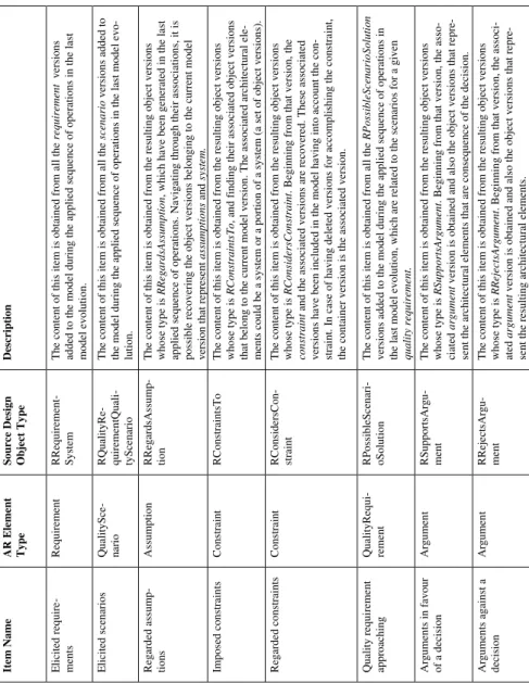
Table 1 offers some examples about how a template should be configured to obtain interesting design rationale information for documenting a software architecture de-sign process. It should be noted that the information is gathered from the object ver-sions that belong to the current model version, since an architectural rationale object documents a model evolution that is generated when that evolution occurs. It should be also noted, that the configuration of the template depends on the design object types included in the domain and relationships defined among them, and finally the preferences of the designers.
4
Case Study
The proposed model has been implemented in a software prototype named TracED [10], which allowed us to carry out several case studies. In this section, we introduce a case study that resembles the design process of architecture of Apache Struts, a free open-source framework for creating Java web applications. Struts is mainly based on the Model-View-Controller architectural pattern and its design process was conducted by following the ADD method [1]. The first decision of the designer is materialised in
the first sequence of operations ( φ1 = { addSystem(‘Struts’) } ), which is applied on the
Root Model Version (an empty model version) and comprises an addSystem operation. The effect of that execution operation is creating the first object version of the
architec-tural model that represents the system whose architecture is going to be designed (V1Struts object version).
Then, for this system the designer defines the quality requirements that should be considered for the intended architecture: Modifiability and Testability. He or she identi-fies also a set of functional requirements and a constraint to impose on the system (WebEnvironment). WebEnvironment constraint is about the context where the future application is going to run, which means that the connections between servers and clients are “stateless”, thus the server does not maintain the state of connections.
Table 1. Examples of possible items of an architectural rationale template
D es cr ip ti o n T h e co n te n t o f th is i te m i s o b ta in ed f ro m a ll t h e re q u ir e m e n t v er si o n s ad d ed t o t h e m o d el d u ri n g t h e ap p li e d s eq u en ce o f o p er at io n s in t h e la st m o d el e v o lu ti o n . T h e co n te n t o f th is i te m i s o b ta in ed f ro m a ll t h e sc e n a ri o v er si o n s ad d ed t o th e m o d el d u ri n g t h e ap p li ed s eq u en ce o f o p er at io n s in t h e la st m o d el e v o -lu ti o n . T h e co n te n t o f th is i te m i s o b ta in ed f ro m t h e re su lt in g o b je ct v er si o n s w h o se t y p e is R R e g a rd sA ss u m p ti o n , w h ic h h av e b ee n g en er at ed i n t h e la st ap p li ed s eq u en ce o f o p er at io n s. N av ig at in g t h ro u g h t h ei r as so ci at io n s, i t is p o ss ib le r ec o v er in g t h e o b je ct v er si o n s b el o n g in g t o t h e cu rr en t m o d el v er si o n t h at r ep re se n t a ss u m p ti o n s a n d sy st e m . T h e co n te n t o f th is i te m i s o b ta in ed f ro m t h e re su lt in g o b je ct v er si o n s w h o se t y p e is R C o n st ra in ts T o , an d f in d in g t h ei r as so ci at ed o b je ct v er si o n s th at b el o n g t o t h e cu rr en t m o d el v er si o n . T h e as so ci at ed a rc h it ec tu ra l el e-m en ts c o u ld b e a sy st em o r a p o rt io n o f a sy st em ( a se t o f o b je ct v er si o n s) . T h e co n te n t o f th is i te m i s o b ta in ed f ro m t h e re su lt in g o b je ct v er si o n s w h o se t y p e is R C o n si d e rs C o n st ra in t . B eg in n in g f ro m t h at v er si o n , th e c o n st ra in t a n d t h e as so ci at ed v er si o n s ar e re co v er ed . T h es e as so ci at ed v er si o n s h av e b ee n i n cl u d ed i n t h e m o d el h av in g i n to a cc o u n t th e co n -st ra in t. I n c as e o f h av in g d el et ed v er si o n s fo r ac co m p li sh in g t h e co n st ra in t, th e co n ta in er v er si o n i s th e as so ci at ed v er si o n . T h e co n te n t o f th is i te m i s o b ta in ed f ro m a ll t h e R P o ss ib le S c e n a ri o S o lu ti o n v er si o n s ad d ed t o t h e m o d el d u ri n g t h e ap p li ed s eq u en ce o f o p er at io n s in th e la st m o d el e v o lu ti o n , w h ic h a re r el at ed t o t h e sc en ar io s fo r a g iv en q u a li ty r e q u ir e m e n t. T h e co n te n t o f th is i te m i s o b ta in ed f ro m t h e re su lt in g o b je ct v er si o n s w h o se t y p e is R S u p p o rt sA rg u m e n t . B eg in n in g f ro m t h at v er si o n , th e as so -ci at ed a rg u m e n t v er si o n i s o b ta in ed a n d a ls o t h e o b je ct v er si o n s th at r ep re -se n t th e ar ch it ec tu ra l el em en ts t h at a re c o n se q u en ce o f th e d ec is io n . T h e co n te n t o f th is i te m i s o b ta in ed f ro m t h e re su lt in g o b je ct v er si o n s w h o se t y p e is R R e je c ts A rg u m e n t . B eg in n in g f ro m t h at v er si o n , th e as so ci -at ed a rg u m e n t v er si o n i s o b ta in ed a n d a ls o t h e o b je ct v er si o n s th at r ep re -se n t th e re su lt in g a rc h it ec tu ra l el em en ts . S o u rc e D es ig n O b je ct T y p e R R eq u ir em en t-S y st em R Q u al it y R e-q u ir em en tQ u al i-ty S ce n ar io R R eg ar d sA ss u m p -ti o n R C o n st ra in ts T o R C o n si d er sC o n -st ra in t R P o ss ib le S ce n ar i-o S o lu ti o n R S u p p o rt sA rg u -m en t R R ej ec ts A rg u -m en t A R E le m en t T y p e R eq u ir em en t Q u al it y S ce -n ar io A ss u m p ti o n C o n st ra in t C o n st ra in t Q u al it y R eq u i-re m en t A rg u m en t A rg u m en t It em N a m e E li ci te d r eq u ir e -m en ts E li ci te d s ce n ar io s R eg ar d ed a ss u m p -ti o n s Im p o se d c o n st ra in ts R eg ar d ed c o n st ra in ts Q u al it y r eq u ir em en t ap p ro ac h in g A rg u m en ts i n f av o u r o f a d ec is io n A rg u m en ts a g ai n st a d ec is io n
The designer incorporates these requirements and constraints by applying a φ2
se-quence of operations on Model Version 1 (φ2 = { addQualityRequirement(V1Struts, ‘
Modifia-bility’, [‘It should be easy to perform changes to the system. The structure and the flow of the application should be clearly defined in order to make its understanding and modification easier. System’s modules should be low coupled.’]), addQualityRequirement(V1Struts, ‘Testability’, [‘The features of the system should be extended, enhanced, or corrected easily, by avoiding bugs caused by unexpected impacts of changes introduced in code. Also refers to the easy way in which the software can demonstrate its faults through (typically execution-based) testing’]),
addFunctionalRequirement(V1Struts, ‘BusinessLogic’, [‘The entire features related to the
busi-ness logic that the systems should support.’]), …, …, …, addConstraint(V1Struts, ‘StatelessConection’, [‘In a Web environment there is no record of previous interactions between servers and clients. Each interaction request has to be handled based entirely on information that comes with it.’]) }). The resulting model version is Model Version 2.
The next designer’s decision is focused on translating the proposed quality re-quirements into measurable elements, to evaluate how close the architecture is of achieving the requirements. Therefore, for each quality requirement some quality sce-narios are proposed, by means of applying φ3 sequence of operations on Model Version
2 (φ3 = { addScenario(V1Testability, ‘ScTestability1’, [‘Writing and running a unit test for a
spe-cific business logic component takes at most 1 person-hour. The test methods exercise the class to be tested, and verify that such a class behaves as it is expected.’],
addScenario(V1Modifiability, ‘ScModifiability1’, [‘A functional requirement changes, which means
that certain functions of the business logic has to be modified. The implementation of the re-quired changes and the tests are completed in 1 day.’]) }). The resulting model version is Model Version 3. The designer continues the design process by incorporating to the
model elements related to the structure and the behaviour of the architecture (φ4 = {
addComponent(V1Struts, ‘WebApplication’, [‘RSubmitRequest’ , ‘RRequestHandling’,
‘RValidate’, ‘RControlActions’, ‘RDataPreparation’, ‘RSendResponse’, ‘RDBAccess’, ‘RBusinessLogic’, ‘RViews’], [ ]) }). Therefore, a first component named WebApplication
and its responsibilities are added by means of an addComponent operation, thus
ob-taining Model Version 4.
At this point of the design process, the designer gives a higher priority to
Modifi-ability quality requirement. Therefore, the architect considers it is convenient applying Model-View-Controller (MVC) architectural pattern as it is a recurring solution for
achieving such quality requirement. Therefore, the next sequence of operation (φ5 = {
applyMVC-go(V1WebApplication, Modifiability) }) comprises applyMVC-go operation, which
refines WebApplication component in a set of components and connectors, with follow an MVC configuration and have the properties and responsibilities that the style
pre-scribes. It should be noted, that Modifiability is the effective argument for the
goal-oriented operation. As a result, Model Version 5 is obtained, where Model, View, and Controller have been included as components of the Struts system. These components
are communicated by means of ConnViewCtrlr, ConnModCtrlr and ConnModView
connectors that represent the interactions among them (V1ConnViewCtrlr,
V1ConnModCtrlr and V1ConnModView object versions). Given that applyMVC-go is
a goal-oriented operation, as a consequence of its execution a series of links are set among the resulting object versions and the intended quality scenario that is related to Modifiability quality requirement. In this way, the intention of the designer for satisfy-ing Modifiability requirement is captured, as well the portion of the architectural design to (possibly) achieving that.
Proceeding in the Struts’ design process, the designer focuses now in the WebEnvi-ronment constraint (V1 WebEnviWebEnvi-ronmentConst). This constraint precludes the Model of notifying to the view of changes, which in a Web environment means that the client (a browser) has to re-query the server to discover modification to the state of the applica-tion. To make the architecture complaint with this constraint, the designer decides to
relax the MVC architecture by deleting the ConnModView connector
(V1ConnModView object version). That decision is materialised in a sequence of
op-erations φ6 that includes deleteConnector-go operation (φ6 = {
deleteConnector-go(V1ConnModView, V1WebEnvironmentConst) }). The last argument of such an operation
(V1WebEnvironmentConst) indicates the considered constraint. As it was presented in
Fig. 7, such an operation adds an RConsidersConstraint object version that links the
container of the deleted connector (V1Struts) and the considered constraint
(V1WebEnvironmentConst), with the aim of explicitly expressing that the constraint has been considered and the architecture fits to it.
The architect continues the design process by refining the current components, and deploying them in specific network nodes. When the designer evaluates the architec-ture model and finds out that the scenarios have been satisfied, the design process ends.
Several queries can be placed to recover the architectural knowledge kept by all the captures. Some examples of queries are: By means of which design operations model version 5 was obtained? Which are the alternative model versions of Model Version 5? How did the WebApplication component change along the design process? Which design operations have the designers applied with the intention of addressing Modifi-ability requirement? Or conversely, why did the architect execute an applyMVC-go operation? Which were the new products generated because of the execution of addComponent in the sequence of operations φ4?
Additionally, the knowledge obtained by the previous queries can be
comple-mented with the AR objects that were generated for each sequence of operations
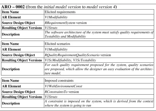
ap-plied during the design process. For example, AR object in Fig. 9 documents the deci-sions made in the evolution from model version 4 to model version 5. We suppose that in this project an AR template was defined with the items in Table 1, and for presenta-tion purposes only items with relevant informapresenta-tion are shown. The descrippresenta-tion item has been manually completed by the designer, but the rest of the items have been automati-cally filled by the documenting mechanism. Moreover, consecutive model evolutions can be grouped, thus merging AR objects in a single documenting object. For instance, AR object in Fig. 10 documents the fragment of design process from the Initial Model Version to Model Version 4.
5
Conclusions
In this article, we have introduced a model for capturing and tracing the software architecture design process. The proposed approach considers the SADP as a composi-tion of design operacomposi-tions that operate on design products. An architectural design proc-ess is documented from the captures of the executed design operations and their re-sults, which fits within the natural course of architecting, without introducing an addi-tional burden for the software architects and developers. The model has two main as-pects regarding AK documentation.
ARO – 0001 (from model version 4 to model version 5)
Item Name Quality requirement approaching
AR Element V1Modifiability
Source Design Object RPossibleScenarioSolution versions
Resulting Object Versions
V1Model, V1View, V1Controller, V-P1, V-P2, C-P1, C-P2, M-P1, M-P2, ConnModView, ConViewCtrlr, ConModCtrlr, MV-R1, MV-R2, VC-R1, VC-R2, MC-R1, MC-R2
Description applyMVC-go was executed to satisfy a scenario related to Modifiability quality requirement. The level of satisfaction should be assessed.
Fig. 9. AR object for documenting a evolution
ARO – 0002 (from the initial model version to model version 4)
Item Name Elicited requirements
AR Element V1Modifiability
Source Design Object RRequirementSystem version
Resulting Object Versions V1Struts
Description The software architecture of the system must satisfy quality requirements of Testability and Modifiability
Item Name Elicited scenarios
AR Element V1Modifiability
Source Design Object RQualityRequirementQualityScenario version
Resulting Object Versions V1ScModifiability, V1ScTestability
Description
For each quality requirement proposed for the system, quality scenarios are proposed, which allow the designer an easy evaluation of the architec-ture model.
Item Name Imposed constraints
AR Element V1WebEnvironmentConst
Source Design Object RConstraintsTo version
Resulting Object Versions V1Struts
Description A constraint is imposed on the system, which is derived from the context where the system is going to run
Fig. 10. AR object for documenting evolution from the initial model version to model version 4
On the one side, it enables the definition of several domains (design object types + design operations to manipulate them), which encloses a portion of AK like basic syn-thesis activities, well known architectural patterns and tactics, and goal-oriented opera-tions. On the other hand, the execution of sequences of operation materialises the de-sign decisions of the architect at each point in the dede-sign process, and, in some cases, which are the intentions of the designer. Captures of made design decisions maintain the performed operations, the effective arguments and resulting products, thus repre-senting another great portion of AK documentation. To enrich and extend the AK gen-erated in each model evolution, a mechanism for semi-automatic documentation is proposed. It aims to reducing the effort of AK producers, thus, helping them to fill templates to document architectural decisions. Several approaches have been proposed for documenting architectural design decisions [1, 3, 5, 6, 8, 9]. Some of them are based in the use of templates with attributes to represent architectural design decisions, like the one of [2, 4].
Despite of the benefits of the proposal on capturing and documenting SADP as the process takes place, the approach has some limitations. The main restriction is inherent to the size of the repository that keeps all the design operations performed and versions generated during an architectural design process. A way of diminishing the problem is the definition of high-level operations, which encapsulate complex decisions (that could comprise dozens basic operations in just one operation). It must be also stated, that in order to obtain advantages of the model, it should be integrated to other archi-tectural design tools.
Acknowledgments
The authors wish to acknowledge the financial support received from CONICET, Universidad Tecnológica Nacional and Agencia Nacional de Promoción Científica y Tecnológica (PAE PICT 02315).
References
1. Bass, L., Clements, P., Kazman, R.: Software Architecture in Practice, Second Edition. Addison-Wesley, Boston, MA (2003)
2. Tyree, J., Akerman, A.: Architecture Decisions: Demystifying Architecture, IEEE Soft-ware 22(2), 19-27 (2005)
3. Jansen, A., Bosch, J.: Software Architecture as a Set of Architectural Design Decisions. In: Proceedings of the 5th IEEE/IFIP Working Conference on Software Architecture, pp. 109-120 (2005)
4. Babar, M. A., Gorton, I.: A Tool for Managing Software Architecture Knowledge. In:
Pro-ceedings of the Second Workshop on Sharing and Reusing Architectural Knowledge Ar-chitecture, Rationale, and Design intent. International Conference on Software Engineer-ing. IEEE Computer Society, Washington, DC, 11(2007)
5. van Heesch, U., Avgeriou, P., Hilliard, R.: A documentation framework for architecture decisions.Journal of Systems and Software, 85 (4), 795-820 (2012)
6. Kruchten, P., Lago, P., van Vliet, H.: Building up and reasoning about architectural knowledge. In: Proceedings of the Second international conference on Quality of Software Architectures (QoSA'06), Springer-Verlag, Berlin, Heidelberg, 43-58 ( 2006).
7. Tang, A., Ali Babar, M., Gorton, I., Han, J.: A survey of architecture design rationale. Journal of Systems and Software, 79 (12), 1792-1804 (2006)
8. Falessi, D., Cantone, G., Kruchten, P.: Value-Based Design Decision Rationale
Documen-tation: Principles and Empirical Feasibility Study. In: Proceedings of the Seventh Working IEEE/IFIP Conference on Software Architecture, 189-198 ( 2008)
9. Avgeriou, P., Kruchten, P., Lago, P., Grisham, P., Perry, D.: Architectural knowledge and rationale: issues, trends, challenges. SIGSOFT Soft. Eng. Notes, 32 (4), 41-46 (2007) 10. Roldán, M. L., Gonnet, S., Leone, H.: TracED: a tool for capturing and tracing engineering
design processes. Advances in Engineering Software, 41 (9), 1087-1109 (2010)
11. Clements, P., Bachmann, F., Bass, L., Garlan, D., Ivers, J., Little, R., Merson, Paulo, Nord, R., Stafford, J.: Documenting Software Architectures: Views and Beyond, Second Edition. Addison-Wesley ( 2010)
12. IEEE: IEEE 1417, Recommended Practice for Architectural Description of Software-Intensive Systems. IEEE Press (2000)