Function for Selected SHA-3 Candidates
A. H. Namin and M. A. Hasan
Department of Electrical and Computer Engineering University of Waterloo
Waterloo, Ontario, Canada Email:{anamin, ahasan}@uwaterloo.ca
Abstract. Hardware implementation of the main building block (com-pression function) for five different SHA-3 candidates is presented. The five candidates, namely Blue Midnight Wish, Luffa, Skein, Shabal, and Blake have been considered since they present faster software implemen-tation results compared to the rest of the SHA-3 proposals. The com-pression functions realized in hardware create the message digest of size 256 bits. We report both ASIC and FPGA implementations. The results allow an easy comparison for hardware performance of the candidates.
Key words: Hash functions, SHA-3, Hardware, Blue Midnight Wish, Luffa, Skein, Shabal, Blake.
1
Introduction
Hash functions have many applications in cryptography mainly in digital signa-tures, message authentication codes (MACs), and other forms of authentication [1]. A public competition recently organized by the National Institute of Stan-dard and Technology (NIST) is underway to select the new StanStan-dard Hash Al-gorithm (SHA-3) [2]. The competition is in response to a weakness found in the SHA family of hash functions [6]. Fifty one submitted algorithms have advanced to the first round of the competition. The source code of these algorithms in C language is available through the NIST SHA-3 webpage [2]. Source codes can be easily compiled for different platforms to measure the performance of each of the proposals. For a complete list of software performance one should refer to ECRYPT Benchmarking of All Submitted Hashes (EBASH) [4] or the SHA-3 zoo website [3].
Unfortunately small percentage of the proposals include hardware implemen-tation results of their work. Also, for the limited number of proposals that were implemented in hardware, different technologies and platforms (ASIC or FPGA) were used. This makes a fair comparison of the implementation results almost impossible. The main motivation behind this work is to address this issue by im-plementing a group of SHA-3 candidates using the same technology and applying the same design approach. We then compare the results of our implementations of the SHA-3 candidates with that of SHA-2.
The SHA-3 candidates we consider here are: Blue Midnight Wish, Luffa, Skein, Shabal and Blake [7]-[11]. These five algorithms are selected since they present faster software implementation results compared to the rest of the pro-posals and are suitable for hardware implementation [5].
2
Design Approach
In general, most hash algorithms use an iterative process to hash the arbitrary size input by successively processing fixed size blocks of the input [1]. This is achieved through a two stage architecture. The first stage which we refer to as
the Preprocessing stage is in charge of padding the input to appropriate size
(usually multiplies of 256 or 512 bits), and then breaking down the message into blocks of smaller fixed sizes (256 or 512 bits).
Next, the message blocks will be processed by the second stage which is re-ferred to as theHash Computation Stage. In this stage, a special function called
the Compression Function is used iteratively through a number of rounds to
create the message digest. The actual number of rounds (or iterations) depends on the number of message blocks. The first round compression function uses the first block of the message along with a predefined initial value called the Initial-ization Vector. The initialization vector is usually created in the preprocessing stage and is just used for the first round of the compression function. For the rest of the rounds, the outputs of each round compression function will be used as the next round initialization vector.
As NIST has requested, all candidates are capable of supporting different message digest sizes of 224, 256, 384 and 512 bits. However, we have just focused on the 256-bit versions in this work. If the authors of a candidate proposed hard-ware architectures for their design, we use that for our hardhard-ware implementation (Skein, Shabal, and Blake). For Luffa and Blue Midnight Wish the authors did not present any hardware architecture in their proposal, hence their algorithms are implemented as pure combinational circuit. Input/Output registers are added at the input and output ports to take into account the loading effect of the in-puts/outputs and also create the register transfer level modules. The inputs for the compression function block is a message of fixed block size (256 or 512 bits according to the algorithm) along with the initialization vector (if needed). The final output of the compression function is a 256 bit message digest.
We present both ASIC and FPGA implementations. For ASIC implementa-tions, VHDL is used to describe the modules in hardware. The code is then sim-ulated using Cadence’s NCSim to verify its functionality. Afterwards, the VHDL code is synthesized to a gate-level netlist using Synopsys’ Design Compiler. Com-pilation parameters are always chosen to maximize the operating frequency of the design.
FPGA implementations are carried out using the same VHDL files used for ASIC implementations. The only difference is the addition of the serial-in parallel-out and parallel-in serial-out modules to transfer the data into or out of the FPGA. Note that FPGA implementations take into account the I/O speed
limits of the FPGA whereas this limitation is not considered for ASIC imple-mentations. We have used the 90 nm CMOS technology from STMicroelectronics for our ASIC implementations. For FPGA implementations, we use Startix III FPGA from Altera.
We base the comparison of our hardware implementations on area and time requirements of each design. For ASIC implementations, we report total area in µm2 which includes area due to combinational circuits as well as I/O registers. We also give the total number of gates used for each design. Note that this parameter varies considerably according to the size and types of gates available in the library. For FPGA implementations as we are using Altera products, the area requirements are given in terms of the number of Adaptive Look-Up Tables (ALUTs) and dedicated logic registers.
For time requirements, we report total delay in nano seconds for fully unrolled designs (Luffa, Skein, BMW, and SHA-2) and is equal to the critical path delay. For sequential designs (Skein-1c, Shabal, Blake, and SHA-2-1c) the total delay is the product of the critical path delay and the required number of clock cycles for each iteration.
For FPGA designs, clock signal of the combinational circuit that implements the compression function is typically different from the clock signal of the I/O modules.
3
Blue Midnight Wish Hash Function
3.1 Algorithm DescriptionThe Blue Midnight Wish (BMW) algorithm has been proposed by Svein Johan Knapskog et al. in [7]. We refer to the variant that creates the 256 bit message digest as BMW-256. The basic data block used is called a word which is 32 bits long. BMW makes use of four different operations in the hash computation stage: bit-wise logical word XOR operation, word addition and subtraction (modulo 232), shift operations (left or right), and rotate left (circular shift left) operation. BMW uses a Double Pipe design to increase the resistance against generic multicollision attacks and length extension attacks [12, 13]. In the double pipe design, the size of the inputs to the compression function are twice the message digest size. The inputs to the compression function are the message blocks Mi
of size 512 bits, along with the initialization vector (previous output of the compression function) which is called the old double pipeHi−1of size 512 bits. The final message digest output bits are the least significant 256 bits of the current double pipeHi.
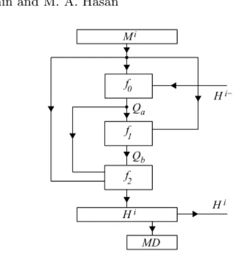
The compression function uses three separate functions to generate the mes-sage digest;f0,f1,f2. The general block diagram for the BMW-256 compression function is shown in Fig. 1. Note that each of the signals in the figure is 512 bits wide.
The first functionf0:{0,1}2∗512−→ {0,1}512 takes two arguments; a mes-sage block Mi and the previous value of the double pipeHi−1, and generates
f0 f1 Mi f2 Hi H i Hi−1 MD Qa Qb
Fig. 1.General block diagram of the compression function in BMW-256
Qi
a=Qi(0,1,...,15)the first part of the quadruple pipe of size 512 bits. Mathemat-ical definition for the functionf0 is shown in Eqs. (1)-(3).
In these equations, initially temporary signalWi
(0,1,...,15)is generated through word by word XOR of the two inputs and addition/subtraction of the words. Note that all addition and subtractions are done module 232, hence carry propagation just exists inside the words. SignalW is then used to create theQa signal using
s0, s1, s2, s3, s4 s-transforms according to Eq. (2). Each transformation accepts a 32-bit word and generates another 32-bit word. Details of s-transforms are shown in Eq. (3). Note that in this equationSHRr(x)/SHLr(x) represents the
shift right/left operation by r bits, while ROT Lr(x) represents the rotate left
W0(i)= (M (i) 5 ⊕H (i−1) 5 )−(M (i) 7 ⊕H (i−1) 7 ) + (M (i) 10 ⊕H (i−1) 10 ) + (M (i) 13 ⊕H (i−1) 13 ) + (M (i) 14 ⊕H (i−1) 14 ) W1(i)= (M (i) 6 ⊕H (i−1) 6 )−(M (i) 8 ⊕H (i−1) 8 ) + (M (i) 11 ⊕H (i−1) 11 ) + (M (i) 14 ⊕H (i−1) 14 )−(M (i) 15 ⊕H (i−1) 15 ) W2(i)= (M0(i)⊕H(i−1) 0 ) + (M (i) 7 ⊕H (i−1) 7 ) + (M (i) 9 ⊕H (i−1) 9 )−(M (i) 12 ⊕H (i−1) 12 ) + (M (i) 15 ⊕H (i−1) 15 ) W3(i)= (M (i) 0 ⊕H (i−1) 0 )−(M (i) 1 ⊕H (i−1) 1 ) + (M (i) 8 ⊕H (i−1) 8 )−(M (i) 10 ⊕H (i−1) 10 ) + (M (i) 13 ⊕H (i−1) 13 ) W4(i)= (M (i) 1 ⊕H (i−1) 1 ) + (M (i) 2 ⊕H (i−1) 2 ) + (M (i) 9 ⊕H (i−1) 9 )−(M (i) 11 ⊕H (i−1) 11 )−(M (i) 14 ⊕H (i−1) 14 ) W5(i)= (M3(i)⊕H(i−1) 3 )−(M (i) 2 ⊕H (i−1) 2 ) + (M (i) 10 ⊕H (i−1) 10 )−(M (i) 12 ⊕H (i−1) 12 ) + (M (i) 15 ⊕H (i−1) 15 ) W6(i)= (M (i) 4 ⊕H (i−1) 4 )−(M (i) 0 ⊕H (i−1) 0 )−(M (i) 3 ⊕H (i−1) 3 )−(M (i) 11 ⊕H (i−1) 11 ) + (M (i) 13 ⊕H (i−1) 13 ) W7(i)= (M (i) 1 ⊕H (i−1) 1 )−(M (i) 4 ⊕H (i−1) 4 )−(M (i) 5 ⊕H (i−1) 5 )−(M (i) 12 ⊕H (i−1) 12 )−(M (i) 14 ⊕H (i−1) 14 ) W8(i)= (M (i) 2 ⊕H (i−1) 2 )−(M (i) 5 ⊕H (i−1) 5 )−(M (i) 6 ⊕H (i−1) 6 ) + (M (i) 13 ⊕H (i−1) 13 )−(M (i) 15 ⊕H (i−1) 15 ) W9(i)= (M (i) 0 ⊕H (i−1) 0 )−(M (i) 3 ⊕H (i−1) 3 ) + (M (i) 6 ⊕H (i−1) 6 )−(M (i) 7 ⊕H (i−1) 7 ) + (M (i) 14 ⊕H (i−1) 14 ) W10(i)= (M (i) 8 ⊕H (i−1) 8 )−(M (i) 1 ⊕H (i−1) 1 )−(M (i) 4 ⊕H (i−1) 4 )−(M (i) 7 ⊕H (i−1) 7 ) + (M (i) 15 ⊕H (i−1) 15 ) W11(i)= (M (i) 8 ⊕H (i−1) 8 )−(M (i) 0 ⊕H (i−1) 0 )−(M (i) 2 ⊕H (i−1) 2 )−(M (i) 5 ⊕H (i−1) 5 ) + (M (i) 9 ⊕H (i−1) 9 ) W12(i)= (M1(i)⊕H(i−1) 1 ) + (M (i) 3 ⊕H (i−1) 3 )−(M (i) 6 ⊕H (i−1) 6 )−(M (i) 9 ⊕H (i−1) 9 ) + (M (i) 10 ⊕H (i−1) 10 ) W13(i)= (M (i) 2 ⊕H (i−1) 2 ) + (M (i) 4 ⊕H (i−1) 4 ) + (M (i) 7 ⊕H (i−1) 7 ) + (M (i) 10 ⊕H (i−1) 10 ) + (M (i) 11 ⊕H (i−1) 11 ) W14(i)= (M (i) 3 ⊕H (i−1) 3 )−(M (i) 5 ⊕H (i−1) 5 ) + (M (i) 8 ⊕H (i−1) 8 )−(M (i) 11 ⊕H (i−1) 11 )−(M (i) 12 ⊕H (i−1) 12 ) W15(i)= (M (i) 12 ⊕H (i−1) 12 )−(M (i) 4 ⊕H (i−1) 4 )−(M (i) 6 ⊕H (i−1) 6 )−(M (i) 9 ⊕H (i−1) 9 ) + (M (i) 13 ⊕H (i−1) 13 ) (1) Qi0=s0(W i 0), Q i 1=s1(W i 1), Qi2=s2(W2i), Qi3=s3(W3i), Q i 4=s4(W i 4), Q i 5=s0(W i 5), Qi6=s1(W6i), Qi7=s2(W7i), Qi8=s3(W8i), Qi9=s4(W9i), Qi10=s0(W10i), Qi11=s1(W11i), Qi12=s2(W i 12), Q i 13=s3(W i 13), Qi14=s4(W14i ), Qi15=s0(W15i), (2) s0(x) =SHR1(x)⊕SHL3(x)⊕ROT L4(x)⊕ROT L19(x) s4(x) =SHR1(x)⊕x s1(x) =SHR1(x)⊕SHL2(x)⊕ROT L8(x)⊕ROT L23(x) s5(x) =SHR2(x)⊕x s2(x) =SHR2(x)⊕SHL1(x)⊕ROT L12(x)⊕ROT L25(x) s3(x) =SHR2(x)⊕SHL2(x)⊕ROT L15(x)⊕ROT L29(x) (3)
The second function f1 : {0,1}2∗512 −→ {0,1}512 takes the same mes-sage block Mi as the first function and the output of the first function Qi
a =
Qi
(0,1,...,15)and generates the second part of the quadruple pipeQib=Qi(16,17,...,31), through EXPAND1 and EXPAND2 expansion functions as shown in Eq. (4). Expansion functions make use of thes-transforms along with the r-transforms
F or ii= 0,1 : Qi(ii+16)=Expand1(ii+ 16) F or ii= 2to15 : Qi(ii+16)=Expand2(ii+ 16) Expand1(j) =s1(Qi(j−16)) +s2(Q i (j−15)) +s3(Q i (j−14)) +s0(Q i (j−13)) +s1(Qi(j−12)) +s2(Q i (j−11)) +s3(Q i (j−10)) +s0(Q i (j−9)) +s1(Qi(j−8)) +s2(Q i (j−7)) +s3(Q i (j−6)) +s0(Q i (j−5)) +s1(Qi(j−4)) +s2(Q i (j−3)) +s3(Q i (j−2)) +s0(Q i (j−1)) +M(ij−16)mod16+M i (j−13)mod16−M i (j−6)mod16+j×0x05555555 Expand2(j) =Qi(j−16)+r1(Q i (j−15)) +Q i (j−14)+r2(Q i (j−13)) +Qi(j−12)+r3(Q i (j−11)) +Q i (j−10)+r4(Q i (j−9)) +Qi(j−8)+r5(Q i (j−7)) +Q i (j−6)+r6(Q i (j−5)) +Qi(j−4)+r7(Q i (j−3)) +Q i (j−2)+r4(Q i (j−1)) +M(ij−16)mod16+M i (j−13)mod16−M i (j−6)mod16+j×0x05555555 (4)
r1(x) =ROL3(x), r2=ROT L7(x), r3(x) =ROT L13(x)
r4(x) =ROL16(x), r5=ROT L19(x), r6(x) =ROT L23(x)
r7(x) =ROL27(x),
(5)
Finally, the last functionf2:{0,1}3∗512−→ {0,1}512 takes two arguments; the message blockMi, and the quadruple pipeQi−1
0,1,...,31=Qia||Qib, (||represents
the concatenation operation) and generates the current value of the double pipe Hi. Mathematical definition for the functionf
XL=Qi16⊕Q i 17⊕Q i 18⊕Q i 19⊕Q i 20⊕Q i 21⊕Q i 22⊕Q i 23 XL=XL⊕Qi24⊕Q i 25⊕Q i 26⊕Q i 27⊕Q i 28⊕Q i 29⊕Q i 30⊕Q i 31 H0i= (SHL 5 (XH)⊕SHR5(Qi16⊕M i 0) + (XL⊕Q i 24⊕Q i 0) H1i= (SHR 7 (XH)⊕SHL8(Qi17⊕M i 1) + (XL⊕Q i 25⊕Q i 1) H2i= (SHR 5 (XH)⊕SHL5(Qi18⊕M i 2) + (XL⊕Q i 26⊕Q i 2) H3i= (SHR 1 (XH)⊕SHL5(Qi19⊕M i 3) + (XL⊕Q i 27⊕Q i 3) H4i= (SHR 3 (XH)⊕Qi20⊕M4i) + (XL⊕Qi28⊕Qi4) H5i= (SHL 6 (XH)⊕SHR6(Qi21⊕M i 5) + (XL⊕Q i 29⊕Q i 5) H6i= (SHR 4 (XH)⊕SHLhQi22⊕M i 6) + (XL⊕Q i 30⊕Q i 6) H7i= (SHR 11 (XH)⊕SHL2(Qi23⊕M i 7) + (XL⊕Q i 31⊕Q i 7) H8i=ROT L 9 (H4i) + (XH⊕Q i 24⊕M i 8) + (SHL 8 (XL)⊕Qi23⊕Q i 8) H9i=ROT L 10 (H5i) + (XH⊕Qi25⊕M9i) + (SHR 6 (XL)⊕Qi16⊕Qi9) H10i =ROT L 11 (H6i) + (XH⊕Q i 26⊕M i 10) + (SHL 6 (XL)⊕Qi17⊕Q i 10) H11i =ROT L 12 (H7i) + (XH⊕Q i 27⊕M i 11) + (SHL 4 (XL)⊕Qi18⊕Q i 11) H12i =ROT L 13 (H0i) + (XH⊕Q i 28⊕M i 12) + (SHR 3 (XL)⊕Qi19⊕Q i 12) H13i =ROT L 14 (H1i) + (XH⊕Q i 29⊕M i 13) + (SHR 4 (XL)⊕Qi20⊕Q i 13) H14i =ROT L 15 (H2i) + (XH⊕Q i 30⊕M i 14) + (SHR 7 (XL)⊕Qi21⊕Q i 14) H15i =ROT L 16 (H3i) + (XH⊕Q i 31⊕M i 15) + (SHR 2 (XL)⊕Qi22⊕Q i 15) (6) 3.2 ASIC Implementation
f
0f
1f
2 .. .M
i .. .H
i−1 .. .H
iQ
aQ
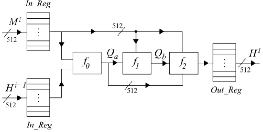
b In_Reg In_Reg Out_Reg 512 512 512 512 512Fig. 2.hardware architecture used for the compression function of the BMW-256
Block diagram of the architecture that is used for the ASIC implementation of the BMW-256 is shown in Fig. 2. In this figure, each line presents a 512-bit wide signal. Inputs Mi and Hi−1 are stored inside the 512-bit input registers
(In Reg). Functionsf1, f2, f3were realized completely as combinational circuits. OutputHican be read from the output register (Out Reg) after one clock cycle.
Input Compression Combinational I/O Register Number of
Size Function Delay Area Area Gates
512 19.20ns 670,887.14µm2 48,746.61µm2 60,033
Table 1.ASIC implementation summary of the BMW-256 compression function
Synthesis results for the BMW-256 compression function are summarized in Table 1. In this table, Compression Function Delay represents the maximum delay between the Input and Output registers. Combinational Area represents the area used by functions f0, f1, and f2. I/O Register Area shows the area utilized by the In reg and Out reg registers. Number of gates may be considered to be an alternative to measure the area requirements of the implementation.
4
Luffa Hash Function
4.1 Algorithm Description
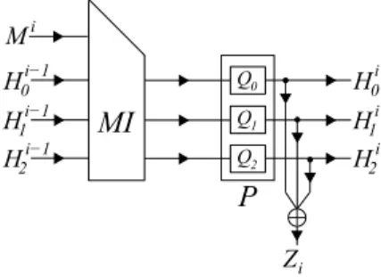
The Luffa algorithm s due to Christophe De Canniere et al. in [8]. It makes use of s-boxes (non-linear permutation) along with shift, and XOR operations to create the output message digest. The basic data block used is a word which is 32 bits long. Luffa’s compression function is called the round function. The structure of a round function for Luffa-256 is shown in Fig. 3. It is made of two separate functions; Message Injection (MI) and Permutation (P).
P
MI
+
Q0 Q1 Q2 Zi Mi H1i−1 0 Hi−1 H2i−1 H1i 0 Hi H2iFig. 3.General block diagram of the compression function (round function) for Luffa-256
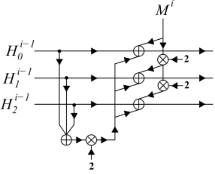
The detail of the message injection module is shown in Fig. 4. In this figure the circled plus sign (⊕) represents bit by bit XOR operation of the variables (256 bit each). Also the circled cross sign (⊗) represents the multiplication operation in the ring ofGF(28)32 using the polynomialφ(x) =x8+x4+x3+x+ 1.
The multiplication operation can be defined as follows; Assume thatA and B are each a vector of 256 bits andA=a[7]||...||a[0] andB=b[7]||...||b[0] where a[i], b[i], i= 0, ...,7 are vectors of 32 bits each. Assume thatB=A⊗2, then we have
b[7] =a[6], b[6] =a[5], b[5] =a[4]
b[4] =a[3]XORa[7], b[3] =a[2]XORa[7], b[2] =a[1]
b[1] =a[0]XORa[7], b[0] =a[7]
(7) The permutation stage (P) for Luffa-256 is made of three similar permutation blocksQj, j= 0,1,2 which work in parallel, as shown in Fig. 3. We refer to these
blocks asPermuteblocks whose input and output sizes are 256 bits each. They can be modelled as a composition of an input tweak and eight iterations of an Step function. The tweak module is just reordering of the wires and does not contain any gates. The block diagram of the Step function is shown in Fig. 5.
In this figure, the 256-bit input to the step function is stored in eight 32-bit registers denoted by ak,0 6k <8 where k represents the register number.
Three main submodules exist in the step function: SubCrumb, MixWord, and the AddConstant. The SubCrumb module is a nonlinear permutation which makes use of 32 similar s-boxes (4-bit input, 4- bit output) in parallel for its operation. The s-box input/output relationship is as follows.
s[16] ={7,13,11,10,12,4,8,3,5,15,6,0,9,1,2,14} (8) The MixWord is a linear permutation module which mixes two words to-gether. The structure of the MixWord is shown in Fig. 6.
In Fig. 5, the AddConstant module performs two XOR operations involving constants according to the parameterskandr(the Step number) to the first and the fourth words. Note that since the value of the constants are predetermined (one input of the XOR gates), the synthesizer will perform optimization and replace the XOR gates by the Inverters or wires as required.
+
H0i−1 H1i−1 H2i−1+
2+
+
+
+
+
Mi 2 2Fig. 5.Block diagram of the Step function module for Luffa-256
4.2 ASIC Implementation
Block diagram of the architecture that is used for the ASIC implementation of Luffa-256 is shown in Fig. 7. In this figure, each line presents a 256-bit wide signal.
InputsMi and Hi−1 are stored inside the 256-bit input registers (In Reg). MI and P blocks (including the s-boxes) are realized completely as combinational circuits. Output Hi can be read from the output register (Out Reg) after one
clock cycle. Synthesis results for the Luffa-256 compression function are summa-rized in Table 2. In this table, the Combinational Area represents the area used by the message injection and permutation (three permute blocks). Each permute block contains a tweak module and eight instances of the step function.
<<< 2 <<< 14 <<< 10 <<< 1
+
+
+
+
32 32 32 32P
MI
+
Zi Mi H1i−1 0 Hi−1 H2i−1Tweak Step Step...
{
Step8 Q...0 .. . In_Reg 256 256 256 256 .. . .. . .. . H1i 0 Hi H2i Out_Reg 256 256 256 .. . .. . .. .
Fig. 7.Hardware architecture used for the compression function of Luffa-256
5
Skein Hash Function
5.1 Algorithm DescriptionFerguson et al. have proposed the Skein algorithm [9]. Skein makes use of 64-bit adders along with shift, and XOR operations to create the output message digest. The basic data block used is a word which is 64 bits long. Skein’s compression function is based onThreefishwhich is a large tweakable block cipher [14]. Skein-256 compression function is made of 72 consecutive rounds of Threefish after four of each there exist a subkey addition module. Subkeys are generated form an input key through the key schedule module. Note that Skein does not make use of the initialization vector the way Luffa and Blue Midnight Wish do.
Skein is built on multiple invocations of the Unique Block Iteration (UBI) which is a variant of the Matyas-Meyer-Oseas hash mode [15]. The basic building block of UBI is shown in Fig. 8.
The structure of the Skein compression function (including the subkey mod-ules) is shown in Fig. 9. Note that the key is not an optional parameter for Threefish and can not be removed from the Skein structure. subkeys are consist of three contributions: key words, tweak words, and a counter value.
Each round of the Threefish block cipher (256 bit version) is made of two instances of a Mix function along with a permutation module. The structure of the Mix function for Threefish-256 is shown in Fig. 10. In this figure the boxed
Input Compression Combinational I/O Register Number of
Size Function Delay Area Area Gates
256 9.96ns 473,318.04µm2 60,277.99µm2 68,884
72 rounds of ThreeFish block cipher
M
i+
>
Fig. 8.Unique Block Iteration (UBI) building block
plus sign (⊞) represents a 64 bit addition (modulo 264), and the circled plus sign (⊕) represents a bit by bit XOR operation. ParametersRd,i are constants that
set the size of the rotate shift operations according to the round number.
Fig. 9.Block diagram of compression function module for Skein-256, 4 out of 72 rounds for Skein-256 including the key
5.2 ASIC Implementation Fully Unrolled/Parallel Design
Block diagram of the architecture used for the hardware implementation of Skein-256 is shown in Fig. 11. In this figure, each line presents a 64-bit wide signal except the input/output wires which are 256 bits wide and the Tweak and key input wires which are 128 and 256 bits respectively.
Input Compression Combinational I/O Register Number of
Size Function Delay Area Area Gates
256 81.92ns 1,605,827.19µm213,788.05µm2 252,725
Table 3.ASIC implementation summary of the Skein-256 compression function
Input messageMi is stored inside the 256-bit input registers (In Reg). The
Mix functions have been realized completely as combinational circuits. After 72 rounds of Mix and Permute functions (including 18 rounds of key addition), one level of XOR gates exist to create the UBI structure of the algorithm. OutputHi
can be read from the output register (Out Reg) after one clock cycle. Synthesis results of the Skein-256 compression function are summarized in Table 3. In this table, the Combinational Area represents the area used by the 144 Mix functions and 18 subkey adder modules exist in 72 rounds of Threefish along with 256 XOR gates in Skein-256.
Sequential Design
Skein compression function architecture presents a highly regular design as shown in Fig. 9. This property can be exploited to create a complete Skein compression function by just implementing one round of the Threefish cipher and a subkey adder module. This can play a major rule when the hashing al-gorithm is implemented for area constrained applications. To this end, we have implemented a second version of the Skein algorithm (Skein-1c) using just one round of the Threefish algorithm.
Note that some modifications to the original round function of Threefish have been allowed to make the design of Skein-1c capable of creating the message digest. The main modification here is the addition of program-ability option to the Mix module, since the rotate shift operation is a function of the round number. Also some extra modules (a counter and two multiplexers and a key schedule module) have been used to create the correct inputs for the round function as shown in Fig. 12. The key schedule module uses circular shift registers along with three 64-bit adders to generate the subkeys.
+
+
64 <<< Rd,i 64 64 64Fig. 11.Hardware architecture used for the compression function of Skein-256
Fig. 12.Hardware architecture used for the compression function of Skein-1c
Fig. 13.Hardware architecture used for the key schedule of Skein-1c
Block diagram of the architecture that is used for key schedule is shown in Fig. 12. It should be noted that the clock used for the key module is four
times slower than the clock used for the rest of the Skein-1c design. Also we had assumed that the two parametersk4 andt2are available at the start of the circuit operation and are loaded into the circular shift registers.
The design is therefore referred to as Skein-1c since it uses one round of the Threefish compression function and it also includes an extra counter. Synthesis results for skein-1c compression function are summarized in Table 4.
Input Critical Number Combinational I/O Register Number of
Size Path Delay of Cycles Area Area Gates
256 3.49ns 72 64,809.98µm2
27,927.33µm2
11,634 Table 4.ASIC implementation summary of the Skein-1c compression function
From Tables 3 and 4 the following can be deduced: the area requirement for the Skein compression function has been reduced from 1,619,615.24µm2 in Skein-256 to 92,737.32µm2in Skein-1c. This reduction comes at the price of increasing the compression function delay from 81.92nsin Skein-256 to 251.28ns in Skein-1c.
6
Shabal Hash Function
6.1 Algorithm DescriptionThe Shabal algorithm has been proposed by Bresson et al. in [10]. Shabal archi-tecture is based on Linear Feedback Shift Register (LFSR), meaning the inputs to the current state of the registers are linear function of the previous state of the registers. Shabal makes use of 32-bit adders/subtractors along with shift, and XOR operations to create the output message digest. The basic data block used is a word which is 32 bits long.
The simplified structure of the compression function block is shown in Fig. 14. In this figure, the boxed plus sign (⊞) represents a 32 bit addition (modulo 232), and the boxed minus sign (⊟) represents a 32 bit subtraction. Circled plus sign (⊕) represents a bit by bit XOR operation. A, B and C are initialization vectors, whileW is a 64 bit counter used to number the message blocks. TheP block represents a keyed permutation module and its details are shown in figure 15.
In Fig. 15, inputs B,C, andM are represented by sixteen words each. The 32-bit registers are shown as one block in the figure. Note that inputAcontains only twelve words and during each clock cycle one word (32 bits) is shifted towards left or right according to the architecture. In this figure modulesU and V are non linear functions defined by:
U :x7→3×x mod232 andv : x7→5×x mod232. In hardware, they can be implemented as small constant multipliers or as two additions and shift for U and three additions and shift for V. Also symbol ⊕represents a bit by bit
XOR operation. Note that the⊕module having 0xF F F...F as one of its inputs, represents an inversion operation.
6.2 ASIC Implementation
We have used the same block diagrams as Fig. 14 and Fig. 15 for hardware implementation of Shabal-256. The only modification applied is the addition of a way to load inputsA,B,CandM into the keyed permutation module. This is achieved by adding a small multiplexer (having one select line and two inputs) to each register storing the inputs. This way all input bits could be loaded into the module, similar to other architectures that have been used in our hardware implementations. Synthesis results for the Shabal-256 compression function are summarized in Table 5.
P
Mi + + A B C − W A B CFig. 14.Block diagram of compression function for Shabal-256
0 11 <<< 15
V
U
+
+
+
+
+
0 8 15 15 0+
0xFFF...F 15 0 6 9 13+
<<< 1 A C M BInput Critical Number Combinational I/O Register Number of
Size Path Delay of Cycles Area Area Gates
256 2.42ns 16 38,244.77µm2 49,041.86µm2 8,065
Table 5.ASIC implementation summary of the Shabal-256 compression function
In this table, the Combinational Area represents the area used byU andV modules along with the area used by the XOR gates and multiplexers. Major part of the area usage belongs to the five 32-bit adders realizing modulesU and V.
7
Blake Hash Function
7.1 Algorithm DescriptionThe Blake algorithm has been proposed by Aumasson et al. in [11]. The basic data block used is called a word which is 32 bits long. Blake makes use of bit-wise logical word XOR operations, word addition (modulo 232), rotate operations (left or right), and permutations in its structure.
Blake is mainly built on previously designed components. Its iteration mode is HAIFA which is an improved version of Merkle-Damgard [16]. Its compression function is a modified version of the ChaCha stream cipher [17]. It also supports an optional salt (a parameter that can be either public or secret) to create the message digest. Blake uses aWide Pipedesign to increase its resistance against collision attacks [18, 19]. The local wide pipe structure of Blake’s compression function is shown in Fig. 16.
rounds
message
initialization finialization
salt counter chain value salt
chain value next chain value
Fig. 16.Block diagram of compression function for Blake-256
As can be seen from the figure, the compression function is made of three main stages: initialization, rounds, and finalization. In the initialization stage a large inner state is initialized from the previous chain value (h), salt (t), and counter (t). The state value is then updated by message-dependent rounds. It is finally compressed to create the next chain value. A sixteen word state v0, v1,· · · , v15 is generated in the initialization stage. The input/output rela-tionship of the initialization step can be mathematically represented as follows.
v0 v1 v2 v3 v4 v5 v6 v7 v8 v9 v10v11 v12v13v14v15 ← h0 h1 h2 h3 h4 h5 h6 h7 s0⊕c0s1⊕c1s2⊕c2s3⊕c3 t0⊕c4 t0⊕c5 t1⊕c6 t1⊕c7 (9)
Ten rounds of transformation are applied in the rounds stage, after the state v is initialized. Each round of transformation is made of eight operations using theGi functions defined as follows.
G0(v0, v4, v8, v12) G1(v1, v5, v9, v13) G2(v2, v6, v10, v14)G3(v3, v7, v11, v15)
G4(v0, v5, v10, v15)G5(v1, v6, v11, v12) G6(v2, v7, v8, v13) G7(v3, v4, v9, v14) (10)
Note that the first four G functions (G0, G1, G2, G3) can be computed in parallel since they apply to different set of inputs i.e.,G0applies tov0, v4, v8, v12. Once the first four G functions are applied, the last four (G4, G5, G6, G7) can be applied. If desirable the last fourGfunctions can be computed in parallel as well. A mathematical definition for functionGi(a, b, c, d) is shown below.
a←a+b+ mσr(2i)⊕cσr(2i+ 1) d←(d⊕a)≪16 c←c+d b←(b⊕c)≪12 a←a+b+ mσr(2i+ 1)⊕cσr(2i) d←(d⊕a)≪8 c←c+d b←(b⊕c)≪7 (11)
In this equation,cis are 32-bit word constants andσis are permutations of
{0,1, . . . ,15}, both defined in the Blake submission documents [11]. Architecture used for the hardware implementation of theGi function is shown in Fig. 17.
Fig. 17.Block diagram of theGi function for Blake-256
After 10 rounds of transformation, the next chain value (h′
0, h′1,· · · , h′7) are extracted from the state values (v0, v1,· · ·, v15) in the finalization stage. The
input/output relationship of the finalization step can be mathematically repre-sented as follows. h′ 0←h0⊕s0⊕v0⊕v8 h′ 1←h1⊕s1⊕v1⊕v9 h′ 2←h2⊕s2⊕v2⊕v10 h′ 3←h3⊕s3⊕v3⊕v11 h′ 4←h4⊕s0⊕v4⊕v12 h′ 5←h5⊕s1⊕v5⊕v13 h′ 6←h6⊕s2⊕v6⊕v14 h′ 7←h7⊕s3⊕v7⊕v15 (12) 7.2 ASIC Implementation
For our hardware implementation we have used the VHDL code available with the initial submission of Blake. The only modification applied is the addition of the input/output registers to take into account the loading effect on the in-puts/outputs. Synthesis results for the Blake-256 compression function are sum-marized in Table 6.
Input Critical Number Combinational I/O Register Number of
Size Path Delay of Cycles Area Area Gates
512 10.4ns 11 191,408.26µm242,204.91µm2 30,262 Table 6.ASIC implementation summary of the Blake-256 compression function
8
Comparison of ASIC Implementation Results
As mentioned earlier, for our implementations we have used the 90 nm CMOS technology from STMicroelecronics; synthesis parameters have always been cho-sen to maximize the operating frequency of the designs.
Area/Delay complexities of ASIC implementations of all of the SHA-3 can-didates considered in this work are listed in Table 7. For simple comparison, the table also includes our two implementations of SHA-2 as described in Appendix A. At the bottom of the table, SHA-2 presents a high-speed 64-round implemen-tation of the SHA-256 architecture, while SHA-2-1c presents a low-area 1-round implementation.
One should note that even though all listed algorithms create the message digest of size 256 bits, their input block size is different. BMW, Blake, SHA-2 and SHA-2-1c use input sizes of 512 bits while Luffa, Skein, Skein-1c and Shabal each accept inputs of size 256 bits. This will make a difference in delay comparisons if the input message size is small (<256) or very large (>>512).
From Table 7, we can see that Luffa-256 presents the fastest architecture (9.96ns) followed by Blue Midnight Wish (19.20ns) and Shabal (38.72ns). Note that for very large input message sizes (>>512) BMW performs slightly better than Luffa, and Shabal still ranks third.
Luffa’s high speed comes from the fact that it does not make use of any adders (32 bit or 64 bit) in the algorithm. The most expensive building block in the Luffa algorithm is the SubCrumb module (s-box) which can be implemented with 5-6 levels of logic gates. The major part of the delay in Blue Midnight Wish and Shabal comes from the 32 bit adder/subtractor modules used in their architectures.
Skein-1c and Shabal architectures present the smallest critical path delay in our comparison table; however a number of clock cycles are required for these two designs to finish one round of compression (72 and 16 clock cycles). This results in architectures with low performance with respect to the total compres-sion time. However these two architectures present the smallest area utilization, approximately 0.092mm2for Skein-1c and ≃0.087mm2for Shabal. Compared to SHA-2-1c both designs require larger area while Skein-1c presents a slower design and Shabal presents a faster one.
Fully unrolled Skein requires the highest area among all proposals listed in the table and it is slightly larger than SHA-2. The area requirement is mainly due to the multiple 64-bit adders used inside the design (in total it uses 231 64-bit adders). BMW ranks second regarding area requirements after Skein; the area is again mainly due to multiple adder/subtractor modules in the design. It is worth mentioning that the high regularity of Skein gives the designer the ability to set trade-offs between area and speed, i.e. Skein with 8 or 16 rounds of Threefish present good trade-offs for area/speed for today’s applications.
In Fig. 18, area and time delays of each of the SHA-3 designs considered in this work are compared with respect to those of SHA-2.
Hash Input Output Compression Number Total Delay Combinational I/O Register Total Area
Size Size Function Delay of Cycles Area Area
BMW 512 256 19.20ns 1 19.20ns 670,887.14µm2 48,746.61µm2 719,633.75µm2 Luffa 256 256 9.96ns 1 9.96ns 473,318.04µm2 60,277.99µm2 533,596.06µm2 Skein 256 256 81.92ns 1 81.92ns 1,605,827.19µm2 13,788.05µm2 1,619,615.24µm2 Skein-1c 256 256 3.49ns 72 251.28ns 64,809.98µm2 27,927.33µm2 92,737.32µm2 Shabal 256 256 2.42ns 16 38.72ns 38,244.77µm2 49,041.86µm2 87,286.64µm2 Blake 512 256 10.4ns 11 118.8ns 191,408.26µm2 42,204.91µm2 233,613.18µm2 SHA-2 512 256 105.1ns 1 105.1ns 1,587,346.92µm229,262.01µm2 1,616,609.00µm2 SHA-2-1c 512 256 2.40ns 64 153.6ns 30,922.68µm2 27,808.79µm2 58,731.47µm2
Fig. 18.Area delay complexities for ASIC implementation
9
FPGA Implementation
For our FPGA implementations we have selected Stratix III FPGA family from Altera. The exact device number used is EP3SL340F1760C3 which represents a 1120 I/O pin FPGA using 65nmtechnology. Quartus II software package from Altera under UNIX environment has been used to implement the designs.
FPGA implementations have been carried out using the same VHDL files used for ASIC implementations. The only difference was the addition of the serial-in parallel-out (SIPO) and parallel-in serial-out (PISO) modules to transfer the data into or out of the FPGA. Using these modules, the restricted number of I/O pins and the I/O speed limits of the FPGA are taken into account which presents a more practical situation. The details of SIPO and PISO modules are shown in Fig. 19.
Fig. 19.SIPO and PISO modules used in FPGA implementations
The SIPO module receives the input data as 32-bit words and then stores them for the proper output selected by the input select lines. Using this method input bits can be loaded into the SIPO module 32-bits at a time. Then the data can be transfered to the compression function in parallel. The PISO module uses a similar idea; it loads the data from the compression function in parallel and then transfers them to the output 32-bits at a time.
FPGA implementation results are summarized in Table 8. Quartus was not able to fit the full unrolled version of Skein and SHA-2 in the selected FPGA
Hash C.F. Clk C.F. Clk I/O Clk I/O Clk Total Combinational Dedicated Logic I/O
Frequency Cycles Frequency Cycles Delay ALUTs Registers Pins
BMW 9.55M Hz 1 400M Hz 32 184ns 12917 2607 111 Luffa 47.04M Hz 1 400M Hz 16 61ns 16552 3247 283 Skein - - - -Skein-1c 161.42M Hz 72 400M Hz 18 491ns 1385 1858 146 Shabal 195.35M Hz 16 400M Hz 32 162ns 1440 4000 289 Blake 46.97M Hz 11 400M Hz 24 294ns 5435 2453 144 SHA-2 - - - -SHA-2-1c 129.79M Hz 64 400M Hz 24 553ns 813 1582 109
Table 8.FPGA implementation summary of the different compression functions
even though the selected one is the largest available FPGA in Stratix III family. In Table 8, C.F. Clk Frequency presents the maximum frequency that the com-pression function could be clocked at. C.F. Clk Cycles represents the required number of clock cycles for the compression function to process the input. The I/O Clk Frequency represents the maximum speed at which the SIPO and PISO modules could be clocked to load the data into and out of the FPGA. The I/O speed is limited by the FPGA itself which in our case is 2.5ns[20]. Total Delay represents the compression function delay in addition to the I/O read and write delay to process a block of data.
The area usage of the FPGA is shown as two separate columns; Combina-tional ALUTs and Dedicated Logic Registers. CombinaCombina-tional ALUTs represents the number of Adaptive Look-Up Tables (ALUTs) used inside the FPGA. It can be used as a measure of the area used by the combinational logic. Dedicated Logic Registers represents the number of memory cells used inside the FPGA. It can be used as a measure of memory usage.
As can be seen from the table, Luffa presents the fastest architecture (61ns) followed by Shabal (162ns) and Blue Midnight Wish (184ns). Unlike in our ASIC implementations, Blue Midnight Wish is dropped from the second place to the third and Shabal is moved up. This might be the result of having a simple small architecture for Shabal versus extensive use of multiple input 32-bit registers for Blue Midnight Wish. Skein-1c and Blake are ranked as the slowest designs the same way they are ranked in our ASIC implementations. Regarding area usage, Skein-1c requires the smallest area followed by Shabal and Blake.
Note that the area requirements of Skein-1c and Shabal are still larger than SHA-2-1c, while their delays are smaller. In Fig. 20, area and time delays of each of the SHA-3 designs on FPGA are compared with respect to those of SHA-2.
10
Conclusions
In this work we have presented hardware implementation results of the compres-sion function block for five SHA-3 candidates (Luffa, Blue Midnight Wish, Skein, Shabal, and Blake). Hardware implementations have been carried out using the
Fig. 20.Area delay complexities for FPGA implementation
90 nm CMOS technology from STMicroelectronics for ASIC and Stratix III from Altera for FPGA. The compression function blocks implemented create the mes-sage digest of size 256 bits. Implementation results allow an easy comparison for hardware performance of the selected candidates.
Among our fully unrolled ASIC designs of SHA-3 candidates namely BMW, Luffa, Skein and Blake, Luffa takes the least amount of area and is about three times smaller than SHA-2. For this type of design, Luffa has the least delay and is about ten times faster than SHA-2. For fully unrolled FPGA design, Luffa also ranks at the top for area and delay.
Among our sequential ASIC designs of SHA-3 candidates, namely Skein-1c, Blake and Shabal, the latter outperforms the other two in terms of area as well as delay. For the same sequential type of designs using FPGA, Shabal and Skein-1c rank at the top for delay and area respectively. Each of these three SHA-3 candidates requires more area but less delay than those of sequential SHA-2-1c. For a given SHA-3 candidate, we are likely to see an improved through-put per unit area in sequential versions of hardware implementation over the fully unrolled version. For example, the throughput per unit area for fully un-rolled Skein is DelayInput Size×Area = 1,929.4bits/(sec µm2), while that for Skein-1c is 10,985.7bits/(sec µm2). Other hash algorithms, such as Blake and Shabal, are also likely to have such improved utilizations of hardware in their sequential designs.
Acknowledgments
This work was supported in part by NSERC strategic project grant awarded to Dr. Hasan. The authors would also like to thank Olga Nam for her assistance with debugging and testing of the VHDL codes.
References
1. Menezes, A.J., Van Oorschot, P.C., Vanstone, S.A.: Handbook of Applied Cryp-tography. The CRC Press series on discrete mathematics and its applications, pp. 321-383, 1997.
2. National Institute of Standard and Technology (NIST): Cryptographic Hash Algo-rithm Competition Website: http://csrc.nist.gov/groups/ST/hash/sha-3/.
3. The SHA-3 Zoo - The ECRYPT hash function website. Website:
http://ehash.iaik.tugraz.at/wiki/The SHA-3 Zoo.
4. European Network of Excellence for Cryptology II (ECRYPT II): ECRYPT Bench-marking of All Submitted Hashes (EBASH): http://bench.cr.yp.to/ebash.html. 5. Fleischmann, E., Forler, C., Gorski, M.: Classification of the SHA-3 Candidates.
International Association for Cryptologic Research (IACR) ePrint archive
6. Wang, X., Yao, A., Yao, F.: New Collision search for SHA-1. Crypto 2005 rump sesson.
7. Gligoroski, D., Klima, V., Knapskog S.J., El-Hadedy, M., Amundsen, J., Mjlsnes, S.T.: Cryptographic Hash Function BLUE MIDNIGHT WISH. Submission to NIST, 2008.
8. Canniere, C.D., Sato, H., Watanabe, D.: Hash Function Luffa: Supporting Docu-ment. Submission to NIST, 2008.
9. Ferguson, N., Lucks, S., Schneier, B., Whiting, D., Bellare, M., Kohno, T., Callas, J., Walker, J.: The Skein Hash Function Family. Submission to NIST, 2008. 10. Bresson, E., Canteaut, A., Chevallier-Mames, B., Clavier, C., Fuhr, T., Gouget,
A., Icart, T., Misarsky, J.F., Naya-Plasencia, M., Paillier, P., Pornin, T., Reinhard, J.R., Thuillet, C., Videau, M.: Shabal, a Submission to NISTs Cryptographic Hash Algorithm Competition. Submission to NIST, 2008.
11. Aumasson,J.P., Henzen, L., Meier, W., C.-W. Phan. R.: SHA-3 proposal BLAKE. Submission to NIST, 2008.
12. Joux, A.: Multicollisions in iterated hash functions. Application to cascaded con-structions. In: Proceeding of CRYPTO 2004. LNCS, vol. 3152, pp. 430440, 2004. 13. Lucks, S.: A failure-friendly design principle for hash functions. In: ASIACRYPT,
2005.
14. Liskov, M., Rivest, R., Wagner, D.: Tweakable Block Ciphers. In: Advances in Cryptology-CRYPTO 2002 Proceedings, Springer-Verlag, pp. 3146, 2002.
15. Matyas, S.M., Meyer, C.H., Oseas, J.: Generating strong one-way functions with cryptographic algorithms. IBM Technical Disclosure Bulletin, vol. 27, no. 10A, pp. 5658-5659, 1985.
16. Biham, E., Dunkelman. O.: A framework for iterative hash functions - HAIFA. ePrint report 2007/278, 2007.
17. J. Bernstein, D.J.: ChaCha, a variant of Salsa20. Web:
http://cr.yp.to/chacha.html.
18. Aumasson, J.P., Meier, Phan, R. C.-W.: The hash function family LAKE. In: 15th International Workshop on Fast Software Encryption, Lecture Notes in Computer Science, pp. 36-53, 2008.
19. Lucks, S.: A failure-friendly design principle for hash functions. In: ASIACRYPT, 2005.
20. ALTERA: Stratix III Device Handbook, Volume 1, May 2009.
21. Federal Information Processing Standards Publication (FIPS PUB) 180-2: Secure Hash Signature Standard (SHS), pp. 1-79, Aug. 2002.
A
Appendix - SHA-2 Hash Function
A.1 Algorithm Description
The basic data block used in SHA-2 (SHA-256) is a word which is 32 bits long. SHA-2 makes use of bit-wise logical word XOR and AND operations along with word addition (modulo 232), rotate right and shift right operations in its struc-ture. SHA-2’s compression function is made of 64 consecutive round functions. The structure of a round function is shown in Fig. 21.
Fig. 21.Block diagram of round function for SHA-2
The inputs to the each round are eight working variables (a, b, c, d, e, f, g, h) 32-bits each along with the two external variablesKtandWt. The set of working
variables (a, b, c, d.e.f.g.h) are initialized at the start of the first round calculation with the previous hash value as follows:
a=H0(i−1) b=H1(i−1) c=H2(i−1) d=H3(i−1) e=H4(i−1) f =H5(i−1) g=H6(i−1) h=H7(i−1) (13)
Kt variables are 32-bit constants and kt variables are created through the
message schedule process as follows:
Wt=
Mt 0≤t≤15
σ1(Wt−2) +Wt−7+σ0(Wt−15) +Wt−1616≤t≤63. (14)
Logical functionsσ0 and σ1 along with the functions used inside the round function (Ch, Maj,P
0,
P
1) are defined as follows:
σ0=ROT R7(x)⊕ROT R18(x)⊕SHR3(x) σ1=ROT R17(x)⊕ROT R19(x)⊕SHR10(x)
X
0
=ROT R2(x)⊕ROT R13(x)⊕ROT R22(x)
X
1
=ROT R6(x)⊕ROT R11(x)⊕ROT R25(x) Ch(x, y, z) = (x∧y)⊕(¬x∧z)
M aj(x, y, z) = (x∧y)⊕(x∧z)⊕(y∧z) (15)
In (15), ROTR represents a rotate right operation and SHR represents a shift right operations. Also, symbol∧represents a logical AND operations,⊕ repre-sents a logical XOR operation and¬represents a logical complements operation. After sixty four rounds of calculations, the output hash is created by the addition (modulo 232) of the last set of working variables (a, b, c, d, e, f, g, h) with the previous hash values as follows:
H0(i)=a+H (i−1) 0 H1(i)=b+H (i−1) 1 H2(i)=c+H2(i−1) H3(i)=d+H (i−1) 3 H4(i)=e+H4(i−1) H5(i)=f +H (i−1) 5 H6(i)=g+H6(i−1) H7(i)=h+H (i−1) 7 (16)
A.2 ASIC Implementation Fully Unrolled/Parallel Design
The architecture used for the ASIC implementation of the SHA-2 is shown in Fig. 22. The previous hash value H(i−1) is stored inside the 256-bit input registers (In Reg). All the round functions have been realized completely as combinational circuits. After sixty four rounds, one level of adders (eight adders in parallel), exists to create the output hash value according to Eq. (16). Output hash values Hi can be read from the output register(Out Reg) after one clock cycle.
Fig. 22.Hardware architecture used for the compression function of SHA-2
Synthesis results of the SHA-2 compression function are summarized in Table 9. In this table, the Combinational Area represents the area mainly used by the 456 32-bit adders exist in the architecture. Small part of the area utilization is used by the sixty four instances of theP
0,
P
Input Compression Combinational I/O Register Number of
Size Function Delay Area Area Gates
512 105.1ns 1,587,346.92µm229,262.01µm2 168,193 Table 9.ASIC implementation summary of the SHA-2 compression function
Sequential Design
Similar to Skein, SHA-2 compression function architecture presents a regular design as shown in Fig. 22. This property can be exploited to create a complete SHA-2 compression function by just implementing one out of sixty four rounds inside the compression function. We have implemented a second version of the SHA-2 algorithm (SHA-2-1c) using just one round which is suitable for area constrained applications. The hardware architecture used for this purpose is shown in Fig. 23.
Fig. 23.Hardware architecture used for the compression function of SHA-2-1c
Note that some modifications have been made to the original round function of SHA-2, to make the design capable of creating the message digest. The main modification is the addition of the message schedule module in charge of gener-ating the Wt parameters from the input message blocks according to Eq. (14).
This has to be done through a recursive process to present the small delay/area requirements of the design.
Hardware architecture used for this purpose is shown in Fig 24. The mes-sage schedule module operates as follows: Initially all input mesmes-sage blocks (M0, . . . , M15) are loaded into the shift register. The shift register itself is made of sixteen registers each made of 32 flip-flops working in parallel. An addition module along with two other modules (σ0, σ1) exist which create theWt
Fig. 24.Hardware architecture of the message schedule module inside the compression function of SHA-2-1c
Also a multiplexer, a counter and a constant module in charge of generating the constants for each round exist inside the design as shown in Fig. 23. Synthesis results for SHA-2-1c compression function are summarized in Table 10.
Input Critical Number Combinational I/O Register Number of
Size Path Delay of Cycles Area Area Gates
256 2.40ns 64 30,922.68µm2
27,808.79µm2
4,207
Table 10.ASIC implementation summary of the SHA2-1c compression function
From Tables 10 and 9 the following can be deduced: the area requirement for the SHA-2 compression function has been reduced from 1,616,609.00µm2in SHA-2 to 58,731.47µm2in SHA-2-1c. This comes at the price of increasing the delay from 105.1nsin SHA-2- to 153.6nsin SHA-2-1c.