1034
DESIGN OF AXIAL FLUX BRUSHLESS DC MOTOR BASED
ON 3D FINITE ELEMENT METHOD FOR UNMANNED
ELECTRIC VEHICLE APPLICATIONS
1H. SURYOATMOJO, R. MARDIYANTO, G. B. A. JANARDANA, M. ASHARI
Department of Electrical Engineering, Institut Teknologi Sepuluh Nopember (ITS)
E-mail: [email protected]
ABSTRACT
The research in order to find an optimal, efficient, and reliable design of brushless dc motor increase significantly. The compact design with high power to weight ratio will support the application of motor drive in electric vehicle. This paper presents the design and analysis of axial flux Brushless DC motor. To analyze the electrical parameters of brushless dc motor such as torque, efficiency, looses, and electric field strength which is modeled and simulated through the Finite Element Analysis Method (FEM). The proposed design is proved with the simulation software with the product of axial flux brushless dc motor with the size of 220 cm using 12 stator slots and 10 rotor poles, generates output power about 27 kW, with a speed of 2388 RPM and torque 109 Nm. This motor has a DC voltage rating of 400 V and the input current to the motor of 101 A.
Keywords: Axial Flux BLDC Motor, Finite Element Method
1. INTRODUCTION
Utilization of electric vehicles required for human life in the future has encouraged researcher and engineers to develop technology to improve efficiency and capability of the electric vehicle. The main technology system in vehicle are consist of batteries, electric motor, connection gears motor and supporting power electronics components. It is became a very important thing for researcher to increase the efficiency from the entire components of supporting electric vehicle. The selection of the optimal design motor is attend to be the improvement in overall efficiency of electric vehicles [1].
The research to develop of motor drive design in electric vehicle has been done to search and maximize the parameters that can improve the efficiency of electric vehicle. One of the design in motor drive that is widely used in electric vehicle research is permanent magnet brushless dc motor. In the research by Chang [2] conclude in his survey that permanent magnet brushless dc motor is better to use as electric vehicle drive because of its low cost, light weight, high efficiency, high speed and large torque. However, Chang et all do not perform 3D analysis of BLDC motor.
In this research, also presents the analysis of electrical parameters of the motor by using the
finite element method based software that analyzes based on these methods. Hopefully, through the design and analysis of axial flux BLDC rotor is able to provide an overview on the motor parameters as reference in the development of electric vehicles.
Brushless dc motors consist of two type motors, axial flux (AF) and radial flux (RF). The Motor drive class for electric vehicle the usage of axial flux a quite compete with radial flux with some advantages in terms of the load withdrawal strength, heat dissipation, water gap, as well as the use of the rotor back iron [3]. Zhang et al [4] in his research conclude that axial flux able to be superior in terms of power density, efficiency and torque. However, Zhang et all also do not perform BLDC motor with 3D analysis.
ISSN: 1992-8645 www.jatit.org E-ISSN: 1817-3195
1035
2. DESIGN OF AF BLDC MOTOR
2.1. Determine parameters with DC Excitation system
Excitation system by using square-wave voltage source is the basic method in order to calculate the parameters in the BLDC system. Where, in each interval there are two phase commutations which are directly excited by the voltage. Therefore, the value of rated power and torque can be determined by the following equations:
P=Tωm=2 EphIph (1)
T=ωP
m= 2 EphIph
ωm (2)
To find the value of a back emf voltage can be done through the flux linkage equations, the equations obtained from the torque equation as follows:
T= 2√√32 πBgqiRo 3
Kr(1-Kr 2
) (3)
T = Torque AF BLDC motor output (Nm) Bg = flux density in the air gap (Tesla) qi = Loading Value (Aturn / m) Ro = The radius of the outer circle (mm) Kr = comparison fingers are inside and outside
2.2. Design of Axial Flux BLDC Motor
The first step in order to determine the motor parameters is by estimating the rated power, voltage, number of phase, power factor (PF) and efficiency of the motor. The following parameters of the motor to be made:
• Power = 25,000 W
• Operational Voltage = 400 V • The number of phase = 3
• Power factor (estimation) = 0.966 • Efficiency (estimate) = 0.8
2.2.1 Current flow
The estimated value of PF (cos θ) is is 0.966 based on the chart combination of numbers slot and pole with balanced concentration winding then the value of the efficiency η also be estimated with a value of 0.8. So the required current in Y connection is:
I= 25.000
3 × 161.31 × 0,8 × 0.966 =66.84 A (4)
For current 66.84 A using 4 pole stator winding design and are arranged in parallel so each winding will has a current about:
66.848 A /4=16.712 A (5)
So it can be used wire standard American Wire Gauge laminated (AWG) that is laminated copper wire with a diameter di of 1.62 mm
2.2.2 Motor Loading Capacity
Calculation of loading capacity in AF BLDC motor can be determined by the following equations
=3
π (6)
From the equation 6 by setting the number of windings of Nph = 34, the value of the loading
capacity can be calculated, as follow: ,
. 334.96 kAturn/m (7)
2.2.3 Calculation of Motor Radius
The first step to obtain radius of motor is by determining the effective surface area of the motor that generates the torque. Effective surface area is a surface between diameter Dse and De. Based on a
research by Campbell (1974) mentioned that the optimal torque for axial flux induction motor the value of ratio between De with Dse is between 0.45
to 0.65. Then, this ratio is called Kd. With the value
of Ds can be obtained from:
Kd=Ds D se
* =0.475 (8)
Ds=0.475×220=104.5 mm (9)
Then,
•Rin ( radius inner) = 0.5 ∙ 104.5 52.5 mm •Rout (radius outer) = 0.5 ∙ 220 104.5 mm •length of core (le) = 110 0 52.5 57.75 mm
• 2345 627892: √52.5 ∙ 110 75.81 mm
2.2.4 Torque and Speed
From practice, maximum torque of 25 kW BLDC motor is 100 Nm. Therefore, it can be used to determine maximum speed of motor as follows:
ω= Pout
T (10)
ω=25000100 =250 rad/s=2387.4 RPM (11)
2.2.5 Air Gap
The proper air gap in the AF BLDC can be estimated by calculating the thickness of stator shoe as follows:
lc= qi
1036 The selected current density is 7A / mm2 and only on the period of acceleration of this current density. Selected conductor fill factor is 0.6 ( linear distribution in conductor). From these data, the thickness of the housing of winding can be determined by:
lc=3 . 7 × 0,8334.96 =19.93 mm (13)
Electrical load also has an important role in determining the air gap. Larger air gap requires thicker magnetic element and consequently increases motor weight. Therefore, from the magnetic field strength generated between the air gap, then selected air gap distance is 1.2 mm.
2.2.6 Determine of Magnetic Field in Air Gap From the above parameters then, it can be used to find the value of the flux density that occurs in the air gap as follows:
T=2√2
√3 πBg334.96×10 3
0.165 30.65<1-0.652= (14) Bg=
173.205
5011.12=3.4 x 10 -2
T (15)
3. SIMULATION AND ANALYSIS
3.1. Analysis of Axial Flux BLDC Motor In this section will perform the design of the BLDC motor stator axial flux using 3D design software. Figure 1 shows the overall design of BLDC model. Table 1 shows the specification of stator. Meanwhile, Table 2 shows details construction of slots in the stator side.
[image:3.612.325.507.239.415.2]Figure 1. Design of AF BLDC assembly using 3D software
Table 1. Specification of Stator
Motor Type Single Sided
Stator Type Slotted stator
Stator Position Upward Number of Stator Slot 12 Outer Diameter of Stator (mm) 220 Inner Diameter Stator of (mm) 104.5 Core Stator Length 30 Material Stator Type D23_50 The use of AF BLDC motors with single sided motor in terms of its simple construction and
capable of generating good power to weight ratio with relatively low manufacturing costs. In order to simplify the motor circuit, the slotted stator has been selected.
[image:3.612.106.286.485.712.2]This comparative figures will be recommended for the implementation of commercial motorcycles. The number of 12 slots and 10 poles is capable of producing a low cogging value and low cost. The value of the back-EMF is also relatively low.
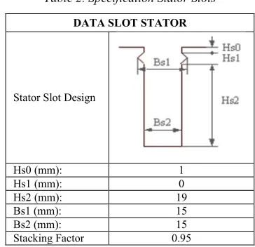
Table 2. Specification Stator Slots
DATA SLOT STATOR
Stator Slot Design
Hs0 (mm): 1
Hs1 (mm): 0
Hs2 (mm): 19
Bs1 (mm): 15
Bs2 (mm): 15
Stacking Factor 0.95
Design specifications of stator slot adapted to the needs of the number of motor windings. The more precise comparison of the extent required by entanglement with the extent of slots used, mechanical losses will be reduced. It also maximizes the stator core area related to the magnitude of the field area that will be created.
[image:3.612.117.280.486.595.2]ISSN: 1992-8645 www.jatit.org E-ISSN: 1817-3195
1037
Table 3. Specification of Stator Winding
DATA STATOR WINDINGS
Number of phase 3
Winding connection Y Number of Parallel Branch 1 Number of winding layers 2 Winding type Whole-Coiled
Coil Pitch 1
Winding Factor 0.93
Number of Coil 34
Number of Wire per
Conductor 1
[image:4.612.281.526.42.382.2]Wire Width (mm) 4.36 Wire Thickness (mm) 1.02 Coil Width (mm) 14.58 Coil High (mm) 9.12 Conductor Material Copper
Table 4 Specification of Rotor
DATA ROTOR
Rotor Type AXIAL PM Rotor Position Bottom Number of poles 10 Outer Rotor Diameter (mm): 220 Inner Rotor Diameter (mm): 104.5 Core Rotor length (mm): 10 Core Rotor Stacking Factor 0.95 Steel Type of Rotor: D23_50 Magnet Length 57.75 Magnet Thickness 8
The rotor specification of axial flux BLDC motor with 10 poles, the outer and inner diameter are considered to the diameter of the stator. Basically, the magnetic field is less sensitive to changes in the thickness of magnet and is most sensitive to the type of material itself. Nowadays, the largest magnetic force that can be used for the application of an electric motor is Neodymium magnet. Its value can reach 1.4 Tesla. Table 4 shows specification of rotor.
3.2. Input Motor Characteristics
Characteristics of the motor input consists of the magnitude of the input current, voltage and cos α. The simulations performed for t=0 up to 6.6 ms. The simulation results show the current value of the IRMS = 82.47 A, with steady state at time t = 2 ms. Voltage in RMS is obtained at 162.31 V, steady state at t = 2 ms. Figure 2 shows the waveform of input current and Figure 3 shows the input voltage.
[image:4.612.98.532.53.438.2]Figure 2. Current Waveform for t = 6.6 ms
[image:4.612.111.278.311.426.2]Figure 3. The Voltage Waveform for t = 6,6 ms
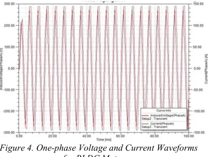
Figure 4. One-phase Voltage and Current Waveforms for BLDC Motor
By comparing the initial design calculations with a rated Pout = 25 kW, the simulation result is
IRMS = 82.47 A, while the the current in RMS is = 66.84 A. This difference is because of the output power from simulation is Pout = 27.307 kW. The
[image:4.612.326.530.415.569.2]1038 α= tI=0-t(V=0)
T × 360° (16)
3.3. Torque-Speed Characteristics
Characteristics of torque and speed is one of the main parameters for calculating the reliability of the motor. In this simulation of AF BLDC motor, according to the previous calculations, is used reference speed 2388 RPM with a torque output value of 100 Nm. With a span of time t1 and t2 are
[image:5.612.310.521.159.564.2]10 ms and 100 ms respectively, on reference speed is 2388 RPM, so the output torque is =109 Nm. The torque value in each time are shown in Figure 5.
Figure 5. Torque for n= 2388 RPM and t = 100 ms
3.4. Input Power Characteristics
The required input power for axial flux BLDC motor can be calculated from eq. 17.
>: 3 ? @ ABC D (17)
So that the input power is 31.22 kW.
3.5. Output Power Characteristics The output power is given by eq. 18
>789 E F (18)
Therefore,
Pout=109 Nm × 238=27.307 Kw (19)
3.6. Efficiency
The efficiency is given by eq. 20, η= Pout
Pin ×100% (20)
Therefore,
η= 2730731322 × 100%=88.45 %
Losses in axial flux BLDC motor mostly caused by stranded losses.
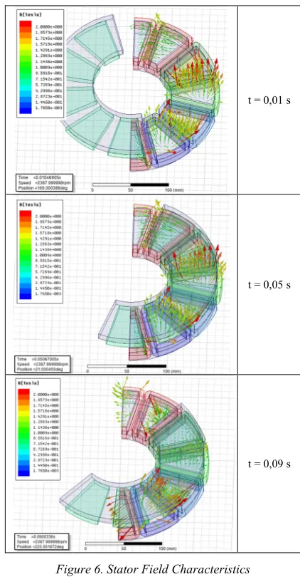
3.7. Stator Field Characteristics
Maximum flux density in stator is 2.03 T. The distribution of flux density in stator are shown in Figure 6 which shows in general that the field
current and the magnetically exposed rotor surface is a linear relationship. The magnetic field stator will produce EMF on the axial flux BLDC rotor. When t = 0.05s field direction goes inward and t = 0.09 s field direction goes outward.
t = 0,01 s
t = 0,05 s
t = 0,09 s
Figure 6. Stator Field Characteristics
3.8. Current Flow Characteristics in Stator The data of current flow on the stator winding of AF BLDC motor, on various times are shown in Figure 7. Current flow direction is affected by input current from the control circuit and the mounted sensor activity which captured the permanent magnet field direction on the rotor.
[image:5.612.91.302.244.398.2]ISSN: 1992-8645 www.jatit.org E-ISSN: 1817-3195
1039 stator shifted according to rotor shifting. Besides, stator field strength mostly occurred in edge side rather than in inner side.
3.10.Losses in Axial Flux BLDC Motor
There are losses that affect AF BLDC motor. In this simulation, stranded losses effect on axial flux BLDC motor is calculated. Stranded losses is produced by windings and this cause excess heat from motor. This stranded losses decrease motor efficiency. Figure 9 shows the value of stranded loss.
t = 0,01 s
t = 0,05 s
[image:6.612.306.527.50.362.2]t = 0,09 s
Figure 7. Current Flow Characteristics in Stator
t = 0,01 s
t = 0,05 s
t = 0,09 s
[image:6.612.90.328.233.699.2]Figure 8. Magnetic Field Characteristics in Air Gap
Figure 9. Stranded Losses on Axial Flux BLDC Motor
4. CONCLUSION
The 3D finite element method can be implemented successfully to model Axial Flux BLDC motor with the specification as follows:
a. Nominal RPM rating is 2388 RPM with the motor torque is 109 Nm and output power 27.307 kW. With this rated, input current is 82.47 A and motor input voltage is 162.31 V. b. The efficiency of Axial flux BLDC motor is
88.45 % because not operates in maximum speed and torque.
REFERENCE:
1040 Transactions On Magnetics, Vol. 40, No. 4, July 2004
[2] L. Chang, “Comparison of AC drives for electric vehicles a report on experts opinion survey,” in IEEE Aerosp. Electron. Syst. Mag., Aug. 1994, pp. 7–10.
[3] D. C. Hanselman, ”Brushless Permanent-Magnet Motor Design”, New York: McGraw-Hill, 1994.
[4] Z. Zhang, F. Profumo and A. Tenconi, “Axial flux machine for electric vehicles,” Elec. Mach. Power Syst., Vol. 24, 1996, pp. 883– 896.
[5] Yilmaz, Kurtuluş. ”Comparison Of Axial Flux And Radial Flux Brushless Dc Motor Topologies For Control Moment Gyroscope Wheel Applications”, Middle East Technical University, 2009.
[6] Jacek F. Gieras, Rong-Jie Wang, Maarten J. Kamper, ”Axial Flux Permanent Magnet Brushless Machines”, Springer, 2008
[7] T.J. Woolmer, M.D. McCulloch, “Analysis of The Yokeless and Segmented Armature Machine”, Oxford University. 2007
[8] Lixin Situ, “Electric Vehicle Development: The Past, Present & Future”. Hong Kong Automotive Parts and Accessory System R&D Centre 78 Tat Chee Ave, 2009.
[9] Merve Yildirim, Mehmet Polat, Hasan Kürüm, “A Survey on Comparison of Electric Motor Types and Drives Used for Electric Vehicles”, F1rat University, 2014.