International Journal of Emerging Technology and Advanced Engineering
Website: www.ijetae.com (ISSN 2250-2459,ISO 9001:2008 Certified Journal, Volume 5, Issue 5, May 2015)
471
System Dynamics Improvement Using Second–Order
Sensitivity Technique for PID Controller for Optimal DC Motor
Speed Control
Adekusibe Kehinde
1, Adejumobi Isaiah
2, Waheed Mufutau
3 1Dept. of Computer Engineering, Ogun State Institute of Technology, Igbesa Nigeria 2Dr. Dept. of Electrical Engineering, Federal University of Agriculture, Abeokuta, Nigeria 3Prof. Dept. of Mechanical Engineering, Federal University of Agriculture, Abeokuta, Nigeria
Abstract – The speed control of the Direct Current (DC) motor is necessary, most especially to achieve effective industrial processes that require constant motor speed. One of the modern ways of controlling DC motor speed control is the use of Proportional-Integral-Derivative (PID) controller. However presence of a set of changes in the DC motor parameters results in high sensitivity of the PID controller to parameter variations in the system. Application of Second-Order Sensitivity Technique (SOST) is one of the effective ways of achieving optimal performance of control system. The work examined the changes to dynamic properties of a separately excited DC motor when applying Second-Order Sensitivity Technique (SOST) to a Proportional-Integral-Derivative (PID) controller. Mathematical equations describing the voltage and corresponding rotational angular speed of the DC motor were applied. Evaluation of responses was carried out using MATLAB. Results showed that applying SOST to PID controller on a sample case improved on the system dynamic properties with settling time, steady-state error and percentage overshoot of 0.245 sec, 0.000 and 0.000% respectively which were within the acceptable system design criteria.
Keyword -- DC motor, speed control, dynamic properties, PID, parameter variations, sensitivity.
I. INTRODUCTION
Direct Current (DC) motors have diverse industrial applications. Their major characteristic is constant speed. However, the speed tends to vary when subjected to load changes. To avoid this variation, speed controller is desired. Apart from the desire to maintain the constant speed, the dynamic properties such as the rise time, settling time, percentage overshoot and steady-state error of the DC motor need to be monitored. In order to limit the speed variation to acceptable values, control measures are applied. One of the commonly used controllers for speed control of DC motor is probable Proportional-Integral-Derivative (PID) controller. However, its limitation is its sensitivity to changes in DC motor parameters such inductance.
A DC motor as originally designed may appear to be inadequate in its performance due variations in some operating conditions such as speed of response and its accuracy [1], [2], [3], [4], [5]. Such variations can be caused by changing environment, aging, ignorance of the exact values of the process parameters, and the natural factors that affect the speed control of the DC motor [6], [7], [8], [9], [10]. One of compensating techniques in reducing errors experienced by DC motor in the course of its operation is the use of PID controllers. A PID controller provides faster response than other types of controllers but is usually harder to control and more sensitive to changes in the system model [11]. Sensitivity of Proportional– Integral–Derivative (PID) controller to parameter variations in compensated DC motor reduces optimal control of the DC motor speed [12]. A control system is optimal when it has low sensitivity to its system parameter variations, it is stable over the range of parameter variations, and the performance continues to meet the specifications in the presence of a set of changes in the system parameters [13], [14], [15].
The sensitivity of a control system to the variations of its system parameters plays an important role in the analysis and synthesis of automatic control systems.
International Journal of Emerging Technology and Advanced Engineering
Website: www.ijetae.com (ISSN 2250-2459,ISO 9001:2008 Certified Journal, Volume 5, Issue 5, May 2015)
472
II. DCMOTOR BEHAVIOURAL PATTERN
A Direct Current (DC) motor is a device that converts electrical energy into mechanical energy. DC motors can be classified as self excited (series, shunt, compound) DC motors and separately excited electric devices. In DC motor speed control system, separately excited motor is usually taken as the study object [20]. A separately excited DC motor is one in which the armature and field windings are electrically separate from each other with the field winding excited by a separate DC source. Its working mechanism hinges on the fact that an electric current in a magnetic field will experience a force. If the current carrying wire is bent into a loop, then the two sides of the loop, which are at right angle to the magnetic field, will experience forces in opposite directions. The pair of forces creates a turning torque to rotate the coil on the basis such that induced emf in the coil is dependent on speed of rotation and torque created in the system is dependent on armature current.
III. MATHEMATICAL MODEL OF THE SEPARATELY
EXCITED DCMOTOR
The model of a DC motor represented by the electric circuit of its armature and free body diagram of its rotor as shown in Figure 1 was mathematically analyzed and simulated. The model employed in this paper consists of a battery and DC motor connected to a load. The DC motor is connected to the battery with voltage source Ea through
sockets which are modeled below. The electric motor used consists of three components such as resistance Ra,
inductance La, and voltage source Ea.
[image:2.612.63.270.492.652.2]
Figure 1: Model of a DC Motor-Source [21].
The mechanical part of DC motor shown in Figure 1 is indicated in Equation 1:
( ) ( ) (1)
And the voltage loop of the DC motor is indicated in Equation 2:
( ) ( ) ( ) + (t) (2)
Equations (1, 2) are combined to determine angular speed ( ) of the DC motor such that:
( )
( ) (3)
Laplace transform analysis of DC motor
Transfer function of DC motor with load can be represented with P(s) such that
( ) ( )( ) (4)
Combining Equations (3, 4) such that:
( )( )
(5)
Substituting Equation (4) into (5), DC motor transfer function becomes:
( ) ( )( )
(6)
The response of DC motor to step input signal can be verified in Simulinks using the mathematical model represented in Equation (6). More details in the parameters of the system dynamics model are given in Appendix I.
Design objective
Here the goals are to design a PID controller that will improve the effect of parameter variations on DC motor speed control and implement Second-Order Sensitivity Technique (SOST) on the simulated PID controller for improved DC motor dynamics for achieving optimal speed control of the DC motor. Comparison study of DC motor dynamics properties such as rise time and percentage overshoot was deployed to specify the use of Second – Order Sensitivity Technique approach for the reduction of the sensitivity of the PID controller to varying values of design parameters such as armature resistance and moment of inertia of the motor, of the DC motor.
The transient response of control systems are described in terms of the swiftness of response in terms of rise time and similarity with the actual response matches the step input as measured in terms of percent overshoot.
International Journal of Emerging Technology and Advanced Engineering
Website: www.ijetae.com (ISSN 2250-2459,ISO 9001:2008 Certified Journal, Volume 5, Issue 5, May 2015)
473
If the system is overdamped, then the peak time is not defined and the rise time, is normally used. The percent overshoot is the ratio of the amount of overshoot to the target steady state value of the system. Percent overshoot represents an overcompensation of the system, and can output dangerously large output signal that adversely affect the performance of a system. For a control system an overshoot of between 0 and 10% is generally acceptable [22].DC motor design
For a unit step input with desired response of 1-rad/sec, the requirement of the design can be chosen such that the percent overshoot is less than 5%.
Combining Equations (1,2,6) and equating
( ) ( )( ) ( )( ) ( ⁄ ) (7)
DC motor is simulated and the problems (a slow response to the step-input, large steady-state error, rise time, and settling time) with uncompensated DC motor are shown through the output response of the system.
PID controller design
Proportional-Integral-Derivative (PID) controllers along with their tuning have been widely used for speed and position control of DC motor [21]. PID controllers constitute an important part of industrial control systems, attempt to correct the error between the reference and the process output, calculates error signal and rapidly adjusts the input to keep error minimal.
[image:3.612.54.284.566.637.2]Figure 3 shows the block diagram of a basic PID controller with its parameters . PID controllers constitute an important part of industrial control systems, attempt to correct the error between the reference and the process output, calculates error signal and rapidly adjusts the input to keep error minimal.
Figure 2: Block diagram of a basic PID controller. Source: The Math Works [23].
From Figure 2, equation two is developed as
( )
( ) ( ) (8)
Combining Equations 7 and 8, error ( ) is computed in equation 9 such that:
( ) ( )
[ (
)( )( ) ]
(9)
Assuming ; ;
and ( ) ( ) control input ( ) is computed as:
( ) ( ) ( ) (10)
Mathematical model of Equation (10) is simulated and run in Simulinks. The responses to varying values of
indicate conflicting goals of minimizing
overshoot and of decreasing rise time.
Tracking of Dc motor with parameter variations
The goal of the controller deployed in this model is to provide tracking to step changes in reference angle speed due to varying values of design parameters such as armature resistance and moment of inertia of the motor, .
Combining Equation (9,10) Control input, ( ) is computed as:
( ) ( ) ( )
[ ( )
( )( ) ]
(11)
Modeling Equation (11) in Simulinks with varying DC motor parameters, and
, PID controller reference tracking on DC
motor parameter variations is implemented. However, the responses from Simulinks indicate that reference tracking is not achieved for any of the parameter values in the model as a result the degree of sensitivity of the PID controller to changes in the model parameters.
System sensitivity
The sensitivity function has been found to be a useful tool for determining the effect of small parameter variations or uncertainties, on the system time response. To allow assessment of sensitivity around optimal points of a given performance index, second-order sensitivity analysis is deployed. The second-order sensitivity indices are defined as
(12)
International Journal of Emerging Technology and Advanced Engineering
Website: www.ijetae.com (ISSN 2250-2459,ISO 9001:2008 Certified Journal, Volume 5, Issue 5, May 2015)
474
( ) ( )
( )
(13)
By equation (13), fast rise time and reduced percentage overshoot are figuratively computed in MATLAB.
IV. RESULTS AND DISCUSSION
DC motor was designed in Simulinks and mathematical equations describing the voltage and corresponding rotational angular speed of the DC motor were applied. SOST was programmed in MATLAB to examine the sensitivity of the PID controller to parameter variations in the system as to obtain the optimal response of the DC motor to a unit-step input.
[image:4.612.56.288.374.549.2]Figure 3 shows that when 1 volt was applied to the system, the motor could only achieve a maximum speed of 0.1 rad/sec, ten times smaller than the desired speed. Also, it took the motor 1.14 seconds to go from 10% to 90% of its final value which might affect its the swiftness to step input response.
Figure 3: Step Response of DC Motor
Implementation of PID control to DC model sped the motor response to unit step input and produced reduced rise time, however large greatly increased the overshoot to
In an attempt to reduce the overshoot caused by large
, increased had been used, the design requirements had been satisfied as shown in Figure 4. However large values of imposed uncertain degree of saturation and this saturation can prevent the controller to project the error when used as a compensator in DC motor configuration.
Figure4: PID Controller with large values
Table 1 shows control parameters compared to the system design criterion such as percentage overshoot < .
Table1:
DC Motor Step Response to different rise times
DC Dynamic
Properties
Ranges of Allowable Dynamic Properties
DC Motor Step Response without PID Controller
DC Motor Step Response using PID Controller
RiseTime, ( )
<1.000 1.140 0.132
International Journal of Emerging Technology and Advanced Engineering
Website: www.ijetae.com (ISSN 2250-2459,ISO 9001:2008 Certified Journal, Volume 5, Issue 5, May 2015)
475
Figure 5 shows the influence of PID controller for reference tracking of parameter variations on DC motor modeled in Simulinks. The negative influence imposed by uncertain degree of saturation was improved; however, the PID controller had low degree of freedom during tuning and in turn resulted to non optimal reference tracking for the model.Figure 5: PID Controller Reference Tracking on DC Motor Parameter Variations with corresponding rise time values: of:A - 0.750sec; B – 0.690sec;
C – 0.800sec; D – 0.900sec; E – 0.775sec; F – 1.300sec; G – 1.250sec; H – 1.125sec; I – 1.000sec; J – 0.950sec.
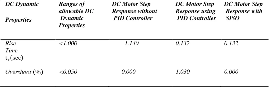
[image:5.612.90.522.450.591.2]The use of Second – Order Sensitivity Technique approach for the reduction of the sensitivity of the PID controller to changes in system parameters was evaluated using equation ( )in Simulinks and the comparative values of percentage overshoot and rise time were indicated in Table 2.
Table 2:
DC Motor Step Response with Second-Order Sensitivity Technique
DC Dynamic
Properties
Ranges of allowable DC Dynamic Properties
DC Motor Step Response without PID Controller
DC Motor Step Response using PID Controller
DC Motor Step Response with SISO
Rise Time
( )
<1.000 1.140 0.132 0.132
Overshoot ( ) <0.050 0.000 1.030 0.000
The closed loop step response in Table 2 shows that the goal of reference tracking was achieved since the response satisfied all of the given design requirements.
V. CONCLUSION
The presence of a set of changes in the DC motor parameters results in sensitivity of the PID controller to parameter variations in the system. Sensitivity of a control power system to the variations of its system parameters is one of the major problems causing inaccuracy in control engineering design.
Implementing SOST on PID controller showed an improvement on the system dynamic properties with rise time, and percentage overshoot of 0.132 sec, and 0.000% respectively which were within the acceptable system design criteria.
International Journal of Emerging Technology and Advanced Engineering
Website: www.ijetae.com (ISSN 2250-2459,ISO 9001:2008 Certified Journal, Volume 5, Issue 5, May 2015)
476
The speed of the DC motor can be optimal when estimated parameter values are used after the implementation of the Second-Order Sensitivity Technique to the DC Motor Control System. It should be noted that if the estimations are obtained around a non-optimal point (where the order derivatives are non-zero), the first-order sensitivity analysis will still provide acceptable estimation of the function; however, for further accuracy and in order to estimate functions around their local optima, second order indices are necessary.The output sensitivity can be reduced by properly designing proportional gain( ), integral gain( ), and derivative gain( ). With the implementation of Second-Order Sensitivity Technique to the DC Motor Control System, the design engineers can choose and adjust the physical design parameters of the motor in order to obtain a proper efficiency when changing DC motor loads.
REFERENCES
[1] Aamir, ,H.O. 2013. Optimal Speed Control for Direct Current Motors using Linear Quadractic Regulator, Journal of Science and Technology – Engineering and Computer Sciences. 14 (2): 49-54. [2] Chapman, S. J. 1999. Electric machinery fundamentals, 3rd edition,
WCB/McGraw-Hill, New York.
[3] Farhad, E. A., Birendra, E. K., Ram, S. C., and Gopal, K. C. 2013. A Comparative Analysis of Controllers Controlling Uncertainty in the Form of 2nd Order Load, Affecting the Robust Position Control of DC Motor, International Journal of Soft Computing and Engineering (IJSCE), 3 (1): 30-33.
[4] George, M., 2008. Direct current electric motors (Control) Switching
circuits (Control) Torque
(Measurement),America Journal of Applied Sciences. 5 ( 3): 1-5. [5] Moleykutty, G. 2008. Speed Control of Separately Excited DC
Motor, Journal of Applied Sciences 5 (3): 227-233.
[6] Jamal, A.M. 2011. Modeling, Analysis and Speed Control Design Methods of a DC Motor, Engineering and Technology Journal, 29 (1): 1-7.
[7] Gaeid, K. S., Jamal A.H., Ali, M. H., Habeeb, M. K. 2013. Static DC Motor Speed Controlled Parameters Correction, British Journal of Applied Science & Technology, 3 (3): 586-597.
[8] Okko, H.B., Huibert, K., and Gjerrit, M. 2002. Design Method for Control System, Dutch Institute of Systems and Control. Winter Term.
[9] Cominos, P., and Munro, N. 2002. PID controllers: recent tuning methods and design to specification”. IEE Proceedings Control Theory and Applications. 149(1): 46-53.
[10] Pagel, M. 2000. PID Control: Tuning and Anti-WindupTechniques, Practical Control Techniques for Control Engineering, workshop at the 2000 American Control Conference.
[11] Karl, J.A., and Kumar, P.R. 2014. Control: A
Perspective,www.elsevier.com/locate/automatical.
[12] Michael, L., Jurrki, K., and James, B. 2010. Sensitivity Analysis in Optimization of Time-Distributed Parameters for a Coronary Circulation Model, Med Prog Technol: 19-24.
[13] Richard, C. D, and Robert, H.B. 2007. Modern Control Systems, 10th
Ed.
[14] Saltelli, A., Chan, K., and Scott, M. 2000. Sensitivity Analysis. John Wiley and Sons, Ltd.: West Sussex, England.
[15] Christopher, H.F. 2002. Identification and Review of Sensitivity Analysis Methods, North Carolina State University Raleigh, NC. [16] Heidari, M. 2006. Computer-Aided Sensitivity Analysis for Optimal
Systems, Journal of Science and Technology:1-6.
[17] Sheng-En, F., Qiu-Hu, Z., Bao, Z., and Xiao-Hua, Z. 2014. Probabilistic and Nonprobabilistic Sensitivity Analyses of Uncertain
Parameters Mathematical Problems inEngineering.7,
http://dx.doi.org/10.1155/2014/23630.
[18] Thorgeir, P. 2014. Parameter Uncertainties in Control System Design, Massachusetts Inst. of Tech.,Cambridge. Measurement Systems Lab.
[19] Ilan, R., and Itzhak, B. 200 Improving Performance of PID Controllers using Adaptive Control, Gordon Center for Engineering Research, Technion IIT, Haifa, Israel: 1-6.
[20] Xisheng, Z., Shuangbao, M., and Hongliang, G. 2015. A Direct Expert Controller Design for Speed Control of DC Motor. Journal of Computational Information Systems, 11 (1): 229-236.
[21] Yaghoub, H., Abolfazl, R. N., Heydar, A. S., and Soheil, S. 2010. Robust Control of DC Motor Using Fuzzy Sliding Mode Control with Fractional PID Compensator, Journal of Mathematics and Computer Science, 1 (4): 238-246.
[22] James, O., and Arazi, N. 2008, Modeling of Speed Control in a DC Motor using Proportional Integral and Derivative Controller, Int. Journal of Control, 14(1): 1137-1146.
[23] Mathworks, (2009), Control System Toolbox User’s Guide, Natick 2000, MA: The Mathworks Inc.
APPENDIX I: System model parameters
Mathematical description of DC motor:
= rotational angular velocity = armature resistance = armature inductance = motor-torque constant
= back emf constant
= moment of inertia of the motor = moment of inertia of the load = angular acceleration
= viscous-friction coefficient of the motor = the motor torque
![Figure 1: Model of a DC Motor-Source [21].](https://thumb-us.123doks.com/thumbv2/123dok_us/8701126.879546/2.612.63.270.492.652/figure-model-dc-motor-source.webp)
![Figure 2: Block diagram of a basic PID controller. Source: The Math Works [23].](https://thumb-us.123doks.com/thumbv2/123dok_us/8701126.879546/3.612.54.284.566.637/figure-block-diagram-basic-controller-source-math-works.webp)