International Journal of Emerging Technology and Advanced Engineering
Website: www.ijetae.com (ISSN 2250-2459,ISO 9001:2008Certified Journal, Volume 3, Issue 9, September 2013)
487
Secured Data Transmission with Novel Parity Bit Scheme
using MAES Algorithm
A. Sriram
1, P. Ramya
2,K. Kishore
3, Infant Selson Joe
4, M.V.Manikandan
5 1Assistant Professor, department of ECE / SRM University, India
2Assistant Professor, department of ECE, SNS College of Engineering /Anna University, India 3,4,5Student, ECE, Cape Institute of Technology /Anna University, India
Abstract-- In transmission and data storage of information security becomes more important in the fast evolution of data exchange. It is more important to protect the confidential data from unauthorized access. To overcome that difficulty, we examine the Advanced Encryption Standard (AES) and modify it, to reduce the calculation of algorithm and for improving the data transmission. In modified AES algorithm instead of using Mixcolumn we use parity bit generator to reflect a high level security and better data transmission.
Keywords-- Exclusive OR, Cipher, SubBytes, ShiftRows. Key expansion, Parity Generator
I. INTRODUCTION
The Data Encryption Standard (DES) which was used earlier for data encryption then extensive research has been done in the areas of improving encryption standards, providing better hardware as well as software architecture for implementing security, because DES uses only a very small 56 bit key length. In particular, we achieve fortification using symmetric key encryption techniques (such as AES, DES) by applying on data as sequence of binary. But unluckily when we apply these techniques to the very large size of text data , it produces significant computational overhead.
The AES algorithm is used in some applications that require fast processing such as smart cards, cellular phones and image-video encryption. However, a central consideration for any cryptographic system is its susceptibility to possible attacks against the encryption algorithm such as statistical attack, differential attack, and various brute attacks. Our research is concerned with optimizing the existing standards of cryptography (AES) for the images and text data encryption. It is also slanting towards exploiting the huge amount of data, in order to attain preferred speed. This edited AES is referred to as Modified-AES algorithm.
The modification is done by replacing the Mixcolumn by paritybit generator, in order to enlarge the security of encryption performance. This modification indubitably increases the efficiency of encryption and makes the algorithm speedier than the existing one.
II. CRYPTOGRAPHY
Secrecy is at the heart of cryptography. Encryption is a practical means to achieve information secrecy. Modern encryption techniques are mathematical transformations (algorithms) with treat messages as numbers or algebraic elements in space and transform them between a region of “ meaning full messages” and region of unintelligible messages.
A message in meaning full region and input to an encryption algorithm is called clear text and unintelligible output from the encryption algorithm is called cipher text. It disregard the intelligible of a message then a message input to an encryption algorithm is conventionally called plaintext which may or may not be intelligible for example, a plain text message can be random nonce or a cipher text message; seen such case in some protocols therefore plaintext and cipher text are a pair of respective notions: the former refer to messages input to, and the letter, output, an encryption algorithm.
III. AESALGORITHM
International Journal of Emerging Technology and Advanced Engineering
Website: www.ijetae.com (ISSN 2250-2459,ISO 9001:2008Certified Journal, Volume 3, Issue 9, September 2013)
[image:2.595.66.275.141.328.2]488
[image:2.595.337.549.368.579.2]Fig.1 Block diagram of AES algorithm
Fig.1 shows the basic building block of the AES core which contains four separated blocks, SubBytes, ShiftRows, MixColumns and AddRoundKey. For the AES algorithm, the length of the input block, the output block and the State is 128 bits. This is represented by Nb = 4, which reflects the number of 32-bit words (number of columns) in the State.
TABLE I
Key-Block-Round Combinations
An implementation of the AES algorithm shall support at least one of the three key lengths: 128, 192, or 256 bits (i.e., Nk = 4, 6, or 8, respectively). Implementations may optionally support two or three key lengths, which may promote the interoperability of algorithm implementations. For the AES algorithm, the length of the Cipher Key, K, is 128, 192 or 256 bits. The key length is represented by Nk = 4, 6, or 8which reflects the number of 32-bit words (number of columns) in the Cipher Key. For the AES algorithm, the number of rounds to be performed during the execution of the algorithm is dependent on the key size. The number of rounds is represented by Nr, where Nr = 10 when Nk = 4, Nr = 12 when Nk = 6, and Nr = 14 when Nk = 8.
The only Key-Block-Round combinations that conform to this standard are given in Table 1.
For both its “Cipher and Inverse Cipher, the AES algorithm uses a round function that is composed of four different byte-oriented transformations:
Byte substitution using a substitution table(S –box) Shifting rows of the State array by different offsets Mixing the data within each column of the State array Adding a Round Key to the State.
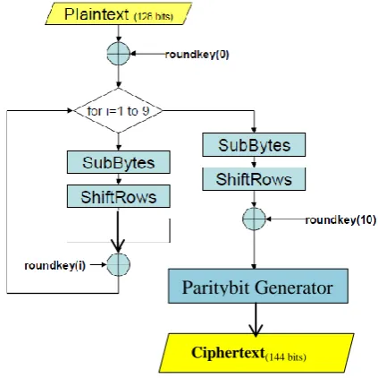
IV. PROPOSED METHOD
To reduce the complexity of calculation and computational overhead, we modified the Advanced Encryption Standard (AES) to reduce the calculation of algorithm and for improving the encryption performance. So we develop and implement a Modified AES based Algorithm for all kind of data. The basic aim to modify AES is to provide less computation and better security for data.
Fig.2 Parity bit Transformation
The modify AES algorithm adjusts to provide better encryption speed. In which the block length and the key length are specified according to AES specification: three key length alternatives 128, 192, or 256 bits and block length of 128bits. We assume a key length of 128 bits, which is most commonly implemented. In Modified-AES encryption and decryption process resembles to that of AES, in account of number of rounds, data and key size. The round function consists of four stages. To overcome the problem of high calculation we skip the Mixcolumn step and to enhance the secure of encrypted data transmission Parity bit generator circuit is added.
Types Key length
(Nk words )
Block size (Nb words)
Number of
rounds (Nr)
AES-128 4 4 10
AES -192 6 4 12
AES -256 8 4 14
Paritybit Generator
International Journal of Emerging Technology and Advanced Engineering
Website: www.ijetae.com (ISSN 2250-2459,ISO 9001:2008Certified Journal, Volume 3, Issue 9, September 2013)
489
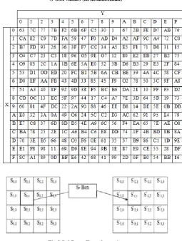
A. Subbytes Transformation
The SubBytes transformation is a non-linear byte substitution that operates independently on each byte of the State using a substitution table (S-box). There are two approaches to implement the sub byte transform. One is by using look up table (LUT) to get the sub byte value for each input; the other is to calculate the sub byte value by mathematical equations. Due to all the operations are in finite field GF (28), there are 256 different sub byte values in total. All the values can be stored in a ROM as a table. When sub byte is in process, the replacement of original value is achieved by look up this table in rom. Therefore, sub byte with LUT is simple to design.
If we think of one value only, the calculation method of the transform is slower than the LUT one. However, considering multiple values transform, only one value can be found by LUT at each time which is not suitable for mass data transform. Although multiple tables can be designed in the system, the resource cost is excessive. On the other hand, calculating method is more suitable for mass values transform. Taking vantage of pipeline structure, registers can easily be introduced between logic gates which means as long as the pipeline is full, the transform results can be received continuously at each clock cycle.
In matrix form, the affine transformation element of the S-box can be expressed as:
[image:3.595.310.566.150.489.2]The S-box used in the Subbytes () transformation is presented in hexadecimal. For example, if=1,1 x {53}, then the substitution value would be determined by the intersection of the row with index „5‟ and the column with index „3‟.
TABLE II S-box values (in hexadecimal)
Fig.3 SubBytes Transformation B. Shiftrows Transformation
ShiftRows is a simple shifting transformation. First row of the state is kept as it is, while the second, third and fourth rows cyclically shifted by one byte, two bytes and three bytes to the left, respectively. In the InvShiftRows, the first row of the State does not change, while the rest of the rows are cyclically shifted to the right by the same offset as that in the ShiftRows.
[image:3.595.49.286.463.569.2]International Journal of Emerging Technology and Advanced Engineering
Website: www.ijetae.com (ISSN 2250-2459,ISO 9001:2008Certified Journal, Volume 3, Issue 9, September 2013)
490
It is a transposition step on the row of the state where each row of the state is shifted cyclically by a certain number of steps. The first row (row 0) is unaltered. The second row (row 1) is shifted by one byte, the third row is shifted by two bytes and the final row is shifted three bytes.Fig.4 Shiftrows Transformation
It also ensures that each byte in each row does not interact solely with their corresponding bytes. There are two schemes to execute the ShiftRows block. The first one is shown in Fig.4 where a mod 4 counter and two 128-bit registers are used. Each of E0 to E15 stands for 8-bit data element.
The data comes into the ShiftRows block in the form of 32 bits and thus it takes 4 clock cycles to get one set of data. It requires a mod 4 counter to identify which column is coming into the ShiftRows block so that the first column can be marked as 00, the second one as 01, and so on. The data comes into the Register 1 in 4 clock cycles. In the fifth clock cycle, the elements in register 1 would be put into the corresponding position in register 2 according to the principle of ShiftRows.
At the same time (the fifth clock cycle) first 32 bits of next 128-bit data would be read into E0-E3 again. At the sixth clock cycle, first 32 bits of the register 2 can be taken out. In general, there need 4 clock cycles to put data into register 1, 4 clock cycles to get out of data from register 2, 1 cycle for “shifting”, and 6 clock cycles latency to get the first 32 bit output. So the counter is not only for identifying the data but also for notifying the registers to get in and output data and shift.
C. Parity Bit Generator
Fig.5 Shiftrows block using a counter
In our proposed algorithm we used Even parity bit generator. From the output of 10th round in MAES algorithm would have 4x4 matrix .In which each cell will have 8 bits. These 8 bits in each cell will be used to generate the even parity bit and the result will be appended in the LSB position. Hence now each cell will have 9 bits. No of bits in each cell is 9 bits. Hence 4x4 matrix will have 144 bits instead of 128 bits.
Fig.6 Parity bit Generator
Fig.7 Parity bit Transformation
P0,0
P0,1
P0,2
P0,3
P1,0
P1,1
P1,2
P1,3
P
2,0P
2,1P
2,2P
2,3International Journal of Emerging Technology and Advanced Engineering
Website: www.ijetae.com (ISSN 2250-2459,ISO 9001:2008Certified Journal, Volume 3, Issue 9, September 2013)
491
D. Key Expansion
The 128 bit key is taken as input in this block and expanded for all the rounds and stored .The keys are then used for every round. Key schedule part is dependent on the sub bytes. The SubByte is calculated both using composite filed and LUT (Look Up Table) method.
[image:5.595.315.548.134.329.2]The LUT is definitely not area efficient rather time efficient whereas the composite field SubBytes technique is just opposite. The area delay curve comes up with the right solution to be chosen. Without making any decision before hand on which key expansion should be used, both the key expansion have been used in the core AES in different combination with different SubBytes. This makes it easy to analyze the performance of each combination.
TABLE III
The Statistics of Key Expansion Block
The key expansion in total takes 12 clock cycles to be completed but data encryption is possible to start right after 4th cycle because of the availability of first few round‟s keys. All the statistics are shown in Table 3.
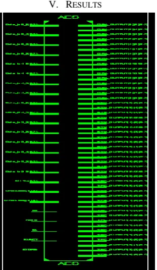
[image:5.595.42.272.332.408.2]V. RESULTS
Fig.9 Parity bit with Encrypted output
VI. CONCLUSION
For the secured transmission of data in crypto systems, the proposed MAES algorithm using symmetric key is fast and on the other hand it provides good security and adds very less overhead on the data. The introduction of the parity bit prediction, both in input and output, increased significantly the fault coverage of the circuit to protect them against both accidental faults and intentional intrusions and attacks, without resorting to expensive solutions requiring large extra memory area in particular those based on the malicious injection of faults into the device for the purpose of extracting the secret information.
Acknowledgements
This work was supported in part by their institution to bring up the ideas and develop the project. The authors would like to thank their Parents, Relatives , Staffs, Principal and the administration and also like to thank the anonymous reviewers for their constructive comments which greatly improved the quality of this work.
REFERENCES
[1] Dominik Engel Thomas stutz,AndreasUhl,”A survey on
JPEF2000 encryption”, Multimedia systems[online] Springer Link Verilog pp.1 -29, ,2008.
[2] Shtewi,A.M. ”An Efficient Modified Advanced Encryption
Standard (MAES) adapted for image cryptosystems” IJCSNS International Journal of Computer Science and NetworkSecurity, VOL.10 No.2, pp 226-232 February 2010Sumira
[3] ShiguoLian,” Quasi-commutative watermarking and encryption for secure media content distribution”,[online], Multimedia Tools and Applications Volume 43, Number 1 / May,2009
Method 256 x 8 bit rom
Xors Slices Minimum field Memory
based
40 1312 5092 6.279ns
Composite field
No 3790 2335 22ns
[image:5.595.89.245.471.739.2]International Journal of Emerging Technology and Advanced Engineering
Website: www.ijetae.com (ISSN 2250-2459,ISO 9001:2008Certified Journal, Volume 3, Issue 9, September 2013)
492
[4] Tanya E. Seidel, Daniel Socek, Designs, Codes and Cryptography [EBOOK], Volume 32 Issue 1-3 (May-July 2004) Kluwer Academic Publishers Norwell, MA, USA
[5] “Announcing the ADVANCED ENCRYPTION STANDARD
(AES)”, Federal InformationProcessing Standards Publication 197 November 26, 2000.
[6] Fahad Bin Muhaya.” Modified AES Using Chaotic Key Generator
for Satellite ImageryEncryption”, Emerging Intelligent
Computing Technology and Applications Volume5754/2009 PP 1014-1024, 2009.
[7] Krishnamurthy G N, V Ramaswamy. “Making AES Stronger: AES with Key Dependent SBox,”IJCSNS International Journal of Computer Science and Network Security, VOL.8No.9, pp 388-398, September 2008.
[8] P. Noo-intara, S. Chantarawong, and S. Choomchuay
“Architectures for MixColumnTransform for the AES” Department of Electronics, Faculty of Engineering, and ResearchCenter for Communications and Information Technology (ReCCIT) King Mongkut'sInstituteof Technology Ladkrabang (KMITL), Bangkok 10520
[9] D. Boneh, R. DeMillo, R. Lipton, “On the Importance of Eliminating Errors in Cryptographic Computations”, Journal of Cryptology, vol. 14, pp. 101-119, 2001
[10] M. Akkar, C. Giraud, “An Implementation of DES and AES, Secure against some Attacks”, Proc. Of CHES‟01, pp. 315-325, 2001
[11] “Advanced Encryption Standard (AES)”, Federal Information Processing Standards Publication 197, November 26, 2001. [12] X. Zhang, K. K. Parhi, “Implementation Approaches for the
Advanced Encryption Standard Algorithm”, IEEE Circuits and Systems Magazine, vol. 2, Issue 4, pp. 24-46, 2002
[13] C. Yen, B. Wu, “Simple Error Detection Methods for Hardware Implementation of Advanced Encryption Standard”, IEEE Trans Computers, vol. 55, no. 6, June 2006, pp. 720-731
[14] G. Bertoni, L. Breveglieri, I. Koren, P. Maistri, V. Piuri, “A parity Code Based Fault Detection for an Implementation of the Advanced Encryption Standard”, Proc. IEEE Int. Symposium on Defect and Fault Tolerance in VLSI, pp. 51-59, Nov. 2002
AUTHOR BIOGRAPHY
A. Sriramis working in SRM University, Chennai as Assistant professor in the department of ECE. He received M.E degree in communication Systems from Cape Institute of Technology, Tirunelveli under Anna University Chennai in 2012 and B.E degree in Electronics and Communication Engineering from Cape Institute of Technology, Tirunelveli under Anna University, Chennai in 2009. He had published 5 papers in International journals and presented 3 papers in national conferences in various fields. He has done the project in the area of embedded systems, VLSI. His area of interests are Digital communication, Micro-processor, Micro-controller and Digital Electronics, VLSI