International Journal of Emerging Technology and Advanced Engineering
Website: www.ijetae.com (ISSN 2250-2459,ISO 9001:2008 Certified Journal, Volume 5, Issue 8, August 2015)
101
Gap Coupled Microstrip Patch Antenna Using CSRR and L
Shape Slot Loaded Ground Plane for Wireless Applications
Sanjai Kumar singh
1, R. K. Prasad
21PG Student, 2Associate Professor, Dept of ECE, MMMUT Gorakhpur, U.P, India-273010
Abstract – A tri-band gap coupled microstrip patch antenna with CSRR (complementary split ring resonator) and L shape slot loaded ground plane is proposed. By employing these structure three resonance bands of 3.42~3.574, 5.68~5.89, and 6.6~7.2 are achieved. This proposed antenna was targeted for tri-band resonance at 3.5 GHz for Wi-MAX, 5.8 GHz for WLAN, and 6.8 GHz for television auxiliary services. The simulated gain is 1.12 dB, 5 dB, and 4.8 dB at lower, middle and upper band respectively. The effect of CSRR structure on the antenna parameters such as: resonance frequency, return loss, and bandwidth are investigated. Simulation of proposed antenna is performed using Ansoft HFSS software; with a substrate thickness of 1.7mm and relative permittivity of 4.4.
Keywords-Microstrip patch antenna (MSA), Metamaterial, CSRR, Gap coupling.
I. INTRODUCTION
Parallel to the rising importance of wireless
communication systems and personnel IT (Information Technologies) services (e.g., Bluetooth), increasing efforts are devoted to the design and implementation of novel microstrip patch antenna. The miniaturization of the patch antenna has become an important issue. To utilize a high permittivity dielectric substrate in reducing the microstrip patch antenna size is a common method. But the antenna more expensive, less radiation efficiency, and have narrow bandwidth. There are many design techniques of the patch antenna have already been proposed to improve the above drawbacks. These antennas have the inserted slot [1], the corrugation structure [2], the iris structure [3], and the shorting pin [4]. A MSA has a dielectric substrate which contain radiating patch on one side and ground plane on other side. The patch is of different size and shapes like square, rectangular, triangular, circular, semi-circular and annular rings. MSAs usually used at higher frequency because the size of antenna is directly tied to the wavelength at resonant frequencies. The patch act as a radiator and the electric field known as a fringe field radiate out into the air after reflecting off the ground plane.
A different type of feeding arrangement has been used in the patch antenna like microstrip line, coaxial, aperture coupling and proximity coupling. Among all microstrip line and coaxial feeds are relatively easy to fabricate [5]. Similarly different types of matching methods are employed like gap coupling, inset feed, quarter wave transformer [6]. Metamaterials are the artificial materials that exhibit properties that may not be found in nature [7]. It contains multiple individual elements such as metals but these materials arranged in periodic patterns. Metamaterials are recently developed materials. Metamaterial is not a special type of materials, if any array of structures of any metal will be able to change the electric and magnetic property of the wave through it ant lead to negative permittivity, negative permeability and refractive index simultaneously, that metallic structure can be called as metamaterial. In 1999, Pendry originally proposed the SRR structure and is the metamaterial resonator having the negative permeability [8]. Based on the babinet principle and the duality concept the CSRR is the negative image of SRR, and the basic mechanism is the same to the both resonators except for excited the axial electric field. The resonant frequency can be easily tuned to the desired value by adjusting the size and geometric parameters of the
CSRR
.
II. ANTENNA DESIGN
The radiating element is rectangular patch that is printed on a FR4_epoxy dielectric substrate with 1.6mm thickness a relative permittivity of 4.4, and a loss tangent of 0.02.
The overall dimension of proposed antenna is
International Journal of Emerging Technology and Advanced Engineering
Website: www.ijetae.com (ISSN 2250-2459,ISO 9001:2008 Certified Journal, Volume 5, Issue 8, August 2015)
102
(a)
(b)
Fig.1. Geometry and configuration of proposed Antenna. (a) Top view, (b) Bottom view.
(a)
(b)
Fig.2. Photographs of the fabricated Antenna. (a) Top view, (b) Bottom view
III. RESULTS AND DISCUSSION
This section shows simulated results of reflection coefficient is shown in Fig.3 as well as parametric results. Simulated return loss at upper frequency range shows good bandwidth while at middle frequency of WLAN it has reasonable frequency bandwidth, but at lower frequency of Wi-MAX it has narrow band compare to reasonable required bandwidth. The return loss of proposed antenna is at centre frequency 3.5GHz, 5.8GHz, and 6.8GHz less than -10 dB. Table I summarizes the results of patch antenna with and without CSRR unit cell in ground plane. Therefore we can conclude that the use of metamaterial structure (CSRR) allows decreasing the antenna resonant frequency and size miniaturization as well.
Fig.3. Simulated return loss for the proposed microstrip patch Antenna.
Fig.4. Simulated return loss for the proposed Antenna geometries without CSRR in ground plane.
25.1 mm
11.1 mm
37 mm 29mm
14 mm 12.3
mm
International Journal of Emerging Technology and Advanced Engineering
Website: www.ijetae.com (ISSN 2250-2459,ISO 9001:2008 Certified Journal, Volume 5, Issue 8, August 2015)
[image:3.612.315.558.100.668.2]103
Table I
comparison between microstrip antenna with and without CSRR.
Parameters
Simulated Resonant Frequency
Simulated BW (-10dB)
Without CSRR
S(1,1) without
CSRR
Simulated Resonant Frequency
Simulated BW
(-10dB) With CSRR
S(1,1) With CSRR
3.56 GHz 134 MHz -14 dB 3.5 GHz 154 MHz -14 dB 6.08 GHz 246 MHz -29.5
dB
5.8 GHz 210 MHz -26.2 dB 7.0 GHz 337 MHz -19 dB 6.8 GHz 600 MHz -33 dB
Fig.5. shows the S11 of the fabricated antenna was
measured by using a network analyzer. The measured working bandwidths of antenna are 110 MHz (3.43 to 3.54 GHz), 160 MHz (5.64 to 5.80 GHz), 680 MHz (6.14 to 7.08 GHz).
Fig.5. Measured and simulated S11 of proposed Antenna.
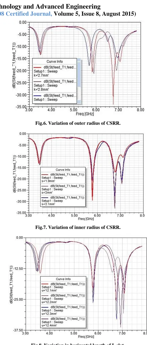
A.Parametric analysis
Fig. 6 shows variation of outer radius of CSRR effects the resonant frequency for larger radius shift occurs at lower frequency while for decreasing it moves up. Fig. 7 shows variation of inner radius of CSRR effects the matching between feed line and patch. Fig. 8 shows as the horizontal L slot length increases lower resonant frequency decreases.
Fig.6. Variation of outer radius of CSRR.
Fig.7. Variation of inner radius of CSRR.
[image:3.612.39.301.158.279.2] [image:3.612.55.282.353.513.2]International Journal of Emerging Technology and Advanced Engineering
Website: www.ijetae.com (ISSN 2250-2459,ISO 9001:2008 Certified Journal, Volume 5, Issue 8, August 2015)
104
B. Radiation PatternThe simulated E-plane (yoz plane) and H-plane (xoz plane) far field radiation patterns of the proposed antenna at three resonant frequencies of 3.5 GHz, 5.8 GHz, and 6.8 GHz are shown in Fig.9. and Fig.10. respectively.
Far field gain (Phi=90)
Theta/Degree vs. dB
(a)
Far field gain (Phi=90)
Theta/Degree vs. dB
(b)
Far field gain (Phi=90)
Theta/Degree vs. dB
(c)
Fig.9. Simulated radiation pattern of proposed antenna at (a) 3.5, (b) 5.8, and (c) 6.8 GHz.
Far field gain (Phi=0)
Theta/Degree vs. dB
(a)
Far field gain (Phi=0)
Theta/Degree vs. dB
(b)
Far field gain (Phi=0)
Theta/Degree vs. dB
(c)
International Journal of Emerging Technology and Advanced Engineering
Website: www.ijetae.com (ISSN 2250-2459,ISO 9001:2008 Certified Journal, Volume 5, Issue 8, August 2015)
[image:5.612.56.283.154.235.2]105
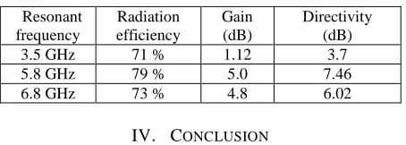
Table II
resulting antenna parameters after simulation.
Resonant frequency
Radiation efficiency
Gain (dB)
Directivity (dB)
3.5 GHz 71 % 1.12 3.7
5.8 GHz 79 % 5.0 7.46
6.8 GHz 73 % 4.8 6.02
IV. CONCLUSION
A tri-band, gap coupled microstrip antenna using CSRR loaded ground plane has been proposed. The desirable performance of tri-band microstrip patch antenna in respect of good gain, return loss, and satisfactory radiation pattern at 3.5 GHz, 5.8 GHz, and 6.8 GHz has been achieved. The proposed antenna has a simple configuration and could Further for future work improvement in bandwidth and radiation efficiency is also an important aspect.
REFERENCES
[1] Wong, K. L. and J. Y. Wu, "Single- feed small circularly polarized square microstrip antenna," Electronics Letters, Vol. 33, 1833{1834, October 1997.
[2] Lee, S., J. Woo, M. Ryu, and H. Shin, “Corrugated circular micro-strip patch antennas for miniaturization," Electronics Letters, Vol. 38, No. 6, 262{263, 2003.
[3] Seo, J. and J. Woo, “Miniaturization of microstrip antenna using iries," Electronics Letters, Vol. 40, 718{719, 2004.
[4] Waterhouse, R., “Small microstrip patch antenna," Electronics Letters, Vol. 31, 604{605, 1995.
[5] Balanis C. A, antenna theory – analysis and design, 3'de d. New York, John Wiley & Sons.
[6] Kumar G. and Ray K.P., broadband microstrip antennas, Artech
House,iNC.London,2003.
[7] D.R.Smith, W.J.Padilla, D.C.Vier, S.C.N.Nasser, S.Schultz, "Composite medium with simultaneously negative permittivity and permeability. " Phys. Rev. Lett. 84 (5): 4184-4187, 2000.