EFFECT OF PROCESS PARAMETERS ON QUALITY OF 3D PRINTED
OBJECTS: AN EXPERIMENTAL INVESTIGATION
Mr. Omkar Prakash Patil
1, Mr. Mahesh Shivaji Kadam
21PG Scholar, Sanjay Ghodawat University, 2Assistant Professor, Sanjay Ghodawat University
---***---
Abstract:Fused deposition modeling (FDM) is an additive manufacturing technology that is implemented to produce parts with less human intervention and shorter product development time. Typical properties such as surface roughness, mechanical strength and dimensional accuracy affect the wear resistance of the parts made with FDM. AM still suffers from long delivery times and the use of excess materials to make large sized solid objects. This fact surely limits the spread of AM technology. On this basis, this paper focuses on material consumption in the solid part of the additive manufacturing and proposes a design strategy in the perspective of process planning. Increasing industrial growth and market demand continuous process improvement is necessary. For process advancement needs to Improve understanding of the parameter effect and reduces manufacturing lead time on the process response. In this paper we are studying Samples with different layer thickness, shell thickness; fill density and printing speed were prepared. Experimental results are comparable to those for different variations.
Keywords:FDM, Additive Manufacturing, PLA, Layer thickness, Top and Bottom thickness, Feed rate, Fill density, Shell thickness
I. Introduction:
Fused deposition modeling (FDM) is a one of the most popular 3D printing technology by using thermoplastic filament as printing material. The filament is melted in hot nozzle and extruded to build 3D physical object. Because of its high reliability, low cost, and simple operation, FDM 3D printers have gained popularity in 3D printing industries especially for small institutes and home users [1]. Additive manufacturing (AM) has gained acceptance in many fabrication arenas due to the advantages of this technology over conventional manufacturing methods, such as the ability to fabricate complex geometries, rapid design to fabrication cycle times, and a lower amount of waste material generated, among others[2].
When the material is extruded from the nozzle, it is cooled from the glass transition temperature to the chamber temperature, causing internal stress due to non-uniformity of deposition rate, resulting in interlayer and inter laminar deformation appearing in the form of cracks, delamination. There are also some manufacturing failures. These phenomena combine and affect the strength and size of the piece[3]. Experimentally it has been demonstrated that the quality of the bond between adjacent layers depends on the
temperature of the envelope and the change in convective conditions within the part of the building during testing of tensile strength and bending samples. The temperature profile shows that the temperature of the lower layer rises above the glass transition temperature and sharply decreases in the direction of movement of the extrusion head. The minimum temperature increases with the number of layers. Microstructural studies have shown that diffusion phenomena are more pronounced in adjacent filaments of the lower layer compared to the upper layer [4].
The areas to be filled in each layer are determined according to the input contours and the self-sustaining capacity of the material. The inner zone confined to the internal contour generated does not affect the shape of the object, it can store the material correctly, so it is not necessary to always fill it. Finally, a skeleton-based route planning method is used to process long, narrow geometry to improve deposition performance and surface quality. Several tests are used to verify the proposed strategy and the results show its effectiveness and feasibility to reduce material consumption, which allows AM to be a more environmentally friendly and sustainable manufacturing method [5].
The process is entirely automatic without the use of tooling and involves less human intervention. The FDM process has hence resulted in applications in functional prototype development in the medical sector, automobile industries, construction industries, space applications and tool and die making. The objective of this research is to study the effects of selected parameters on the FDM process response. Investigation is focused on parameters involved in determining the method of product selection, and material selection for the product application. These parameters include nozzle temperature, material pouring speed, nozzle size and other dependent parameters which are defined in the following section.
II. Methodology
A. Materials and Methods
The 3DP machine (I 3D Minds, INDIA) is equipped with a number of useful features, such as automated setup and automated Manufacturing it is like once the program is fitted and runs it will stops until the product becomes finish. It has maximum built envelop 190×190×180mm and nozzle diameter is 0.4mm. The samples were designed by using SolidWork software of Version 2016. For the process parameter control while manufacturing slicing software called CURA used to prepare samples.
B. Specimen preparation
The PLA material was loaded into a 3D Printing machine. The samples were prepared based on the various combinations as shown in Table no 1. First of all the sample with predefined shape, pore and strut sizes design were prepared in SolidWorks CAD software and converted in to IGS file format. Then the file was transferred to CURA software for varying different process parameters like different layer height (0.1 mm and 0.4 mm), fill densities (10% and 20%), top/bottom thickness or layer thickness (0.4mm and 0.8mm), shell thickness (0.4mm and 0.8mm) at constant printing speeds. It provides a detail combination of 3 different samples for the process parameters. In CURA software the sample file was converted into standard STL file format which is compatible with all AM machines. After preparation of STL file, it was inserted in to FDM machine and run the file. For all experiments, the nozzle diameter 0.4 mm was used for preparation of specimens. The nozzle was maintained a temperature of 210 ºC for the extrusion of the PLA material and the build platform was maintained at 70 ºC. The printer prints the layer through the conventional nozzle print head onto bed, one layer onto another, from the lowest cross-section to the highest, and the same test setup was used for all samples. After printing Let the printed models and building platform are dried and cooled at room temperature then removed the specimen. After printing, the printed samples are usually post hardened or infiltrated for maximum strength. In this research, It was observed that variations in fabrication time of preparation of test samples when the different built parameters. The post hardening was overlooked to investigate the unconditional effect of printing parameters on physical properties of the printed samples.
Sample
parameter Sample 1 Sample 2 Sample 3
Layer height 0.1 0.1 0.4
Fill density 10% 10% 20%
Shell thickness 0.4 0.8 0.8
Top and
bottom thickness or layer thickness
0.4 0.8 0.8
Printing speed 40mm/se
c 40mm/sec 40mm/sec
Table: 1: Various process conditions for specimen preparation
III. Discussion:
A. Different process parameters of specimens:
Layer height (mm):
This is the most important setting to determine the quality of your print. Normal quality prints are 0.1mm, height quality is 0.06mm. It can go up to 0.25 mm with a common printer for very fast printing at low quality.
Shell thickness (mm):
The shell thickness is the thickness of outside shell in the horizontal direction. This is used in combination with the size of the nozzle to define the number of lines of the printer.
Bottom/top thickness (mm):
This controls the thickness of the bottom and top layer, the amount of solid layers put down in calculated by the layer thickness and this value. Having this value a multiple layer of the thickness of the layer is logical, and keeping it close to the thickness of the wall to form a uniformly strong part.
Fill density (%):
This controls how densely filled the insides of your print will be. For a solid part use 100% and for an empty part use 0% fill density. A value around 20 is usually enough. This won’t affect the outside of the print and adjusts how strong the part becomes.
Printing speed (mm/s):
Printing speed is the speed at which printing happens by the movement of printing head. A well-adjusted printer can reach 150mm/s, but for good quality prints it need to print slower. Printing speed depends on lot of factors, so it requires optimal setting for this experiment.
B. Self-supporting-based strategy
In the AM process, parts are formed by joining materials layer upon layer, which means each layer is deposited on its prior layers. Such fabrication paradigm would result in an intuitive fact that the current layer cannot be deposited successfully if there are substantial overhanging areas without the assistance of some additional supports underneath. This is the reason why support structure is required among a large group of AM techniques except that some powder-based AM processes can be fully self-supported by the powders[5].
volume to the maximum extent, the self-supporting ability of fabricated parts should be fully considered .After the part has been sliced into a large number of layers and deposited with beads; the self-supporting angle is analyzed as Fig. 1(b). With a given layer thickness t and the overhang length l, the self-supporting angle α is expressed.
The outmost bead on the upper layer is supposed to be balanced under the combining action of gravity, normal force from the below layers, and the lateral and vertical adhesive force with its adjacent beads. As the interaction between bonded materials is quite complex and mutable, the detailed force analysis is difficult to conduct and cannot provide a
reliable benchmark for the determination of self-supporting angle.
In general, the self-supporting angle is affected by the mass ratio 1 of overhanging part and inside part on the outmost deposited bead.
[image:3.595.188.523.239.372.2]Where w is the bead width, which is determined by some process parameters as illustrated in Fig. 1(c). For example, the bead width is determined by the nozzle size and the layer thickness in extrusion-based AM processes[6].
Fig. 1. Demonstration of self-supporting capability[6]
C. Path planning
For a specific layer, the areas to be filled are confined by the exterior boundary and the generated internal contours, and commonly have long and narrow geometrical property. To fill shapes with such type of geometry, general filling path patterns cannot achieve desirable filling quality or long build time is required. As illustrated in Fig. 2, the general contour path would bring in several overfill issues when the distance between adjacent path elements is smaller than the expected path gap. This issue is very common in filling long and narrow geometry with contour parallel path patterns. One of typical direction parallel path patterns, zig-zag path, would avoid the overfill issue, but long build time is required due to many sharp turns along the filling paths[5].
Fig. 2. Illustration of two general path patterns for filling the long and narrow geometry[5].
IV. Experimental specimen’s Response:
In first specimen nozzle speed, nozzle temperature and bed temperature is constant. we found that the fill density 10%, shell thickness 0.4mm which kept as minimum as possible and also top and bottom thickness is 0.4mm that’s why the author observed that the top layer falls inside the zig-zag filled gaps due to form uneven top surface. While printing fist specimen’s top layer the density gaps were reduces the contact between extruded material and last layer that’s why material filament stretching occurs over the gaps this affects the uneven layer deposition on top surface shows in fig. 3 (1).
In second specimen only increases the shell thickness and top and bottom thickness from 0.4 to 0.8mm this effects the small improvement in the side walls and proper layer deposition over each other but the top surface occurs the material filament falling in the density gaps the specimen shows in fig. 3 (2).
[image:3.595.49.276.588.720.2]Fig. 3. Top view of all specimens
[image:4.595.52.272.302.432.2]The specimen 3 shows in fig. 4 was made with increased layer height of 0.4 so there layer stacking is not proper so layer splitting is occurred there[8].
Fig, 4. layer splitting in specimen 3
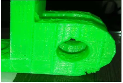
The angle between the tangent plane along the part surface of the area and the building direction is the self-supporting angle α is increased[9]. While printing the hole and the over hanging curve extrusion of filament from nozzle on the upper layer is supposed to be balanced under the combining action of gravity, normal force from the below layers, and the lateral and vertical filament force occurs the bending on the overhanging curvature area[10] and due to zig-zag pattern excess uneven material layer deposition occurs shows in fig. 5.
Fig 5. Lack of self supports in holes and bottom of curved area
V. Conclusion
An AM process planning approach emphasizing on the optimization of FDM process planning by varying the process parameters has been developed in this paper to reduce the material consumption of additively fabricated parts, particularly for large and solid objects. The developed framework proposes an optimal internal topology considering the requirement of minimal wall thickness and the self-supporting capability. The optimal internal topology minimizes the total consumed materials by reducing the volume of the whole part to be filled, and thus saves the build time. Instead of the input CAD file itself, its sliced data is adopted in the internal optimization to reduce the computational cost and avoid errors in addressing 3D. Geometric operations, meanwhile, the filling quality are enhanced by utilizing a skeleton-based method for evaluation and path optimization.
VI. References
[1] Yang Yang, Yonghua Chen, Ying Wei1, Yingtian Li; “3D printing of shape memory polymer for functional part fabrication”; International Journal of Advance Manufacturing Technology;2015.
[2] Angel R. Torrado, Corey M. Shemelya, Joel D. English, Yirong Lin Ryan B. Wicker, David A. Roberson; “Characterizing the Effect of Additives to ABS on the Mechanical Property Anisotropy of Specimens Fabricated by Material Extrusion 3D Printing”;(2015).
[3] V. Vijayaraghavan, A. Garg, Jasmine Siu Lee Lam, B. Panda, S. S. Mahapatra; “Process characterization of 3D-printed FDM components using improved evolutionary computational approach”; International Journal of Advance Manufacturing Technology;(2014).
[4] K.G. Jaya Christiyana, U. Chandrasekharb, K. Venkateswarluc; “A study on the influence of process parameters on the Mechanical Properties of 3D printed ABS composite”; IOP Conf. Series: Materials Science and Engineering; (2015).
[5] Yuan Jin a, Jianke Dua, Yong Heb; “Optimization of process planning for reducing material consumption in additive manufacturing”; Journal of Manufacturing Systems, (2017), 44, 65–78.
[6] Jun Wu, Charlie C.L. Wang, Xiaoting Zhang, Rudiger Westermann; “Self-Supporting Rhombic Infill Structures for Additive Manufacturing”; Computer-Aided Design, (2016).
[image:4.595.57.267.595.737.2]© 2018, IRJET | Impact Factor value: 6.171 | ISO 9001:2008 Certified Journal | Page 4119 Advances in Thermal Systems, Materials and Design
Engineering, (2017), 1-6.
[8] Arghavan Farzadi, Mehran Solati-Hashjin1, Mitra
Asadi-Eydivand, Noor Azuan Abu Osman; “Effect of Layer Thickness and Printing Orientation on Mechanical Properties and Dimensional Accuracy of 3D Printed Porous Samples for Bone Tissue Engineering”; (2014).
[9] Do-Sik Shim, Gyeong-Yun Baek b, Jin-Seon Seo,
Gwang-Yong Shin, Kee-Poong Kim, Ki-YongLee; “Effect of layer thickness setting on deposition characteristics in direct energy deposition (DED) process”; Optics & Laser Technology, (2016), 86, 69-78.
BIOGRAPHIES:
O P. Patil, received the B.E. degree in mechanical engineering from Shivaji University, Kolhapur, India, in 2017 and He is currently pursuing the M.Tech. degree in mechanical engineering at Sanjay Ghodawat University, India.
M S. Kadam, received M.E Degree in Mechanical engineering from KIT College of Engineering, Kolhapur, India 2014 and He is currently pursuing the Ph.d Degree in mechanical engineering at Shivaji University From 2016, he is assistant professor at Sanjay Ghodawat College of engineering. And his research area is Nano Composite and other research interest is Finite Element analysis.
[10] John D. Williams, Carl R. Deckard; “Advances in
![Fig. 1. Demonstration of self-supporting capability[6]](https://thumb-us.123doks.com/thumbv2/123dok_us/8135682.798195/3.595.49.276.588.720/fig-demonstration-of-self-supporting-capability.webp)