© 2017, IRJET | Impact Factor value: 4.45 | ISO 9001:2008 Certified Journal
| Page 707
AN AVERGE BASED ORIENTATION FIELD ESTIMATION METHOD FOR
LATENT FINGER PRINT MATCHING.
B.RAJA RAO
1, Dr.E.V.KRISHNA RAO
21 Associate Professor in E.C.E Dept ,KITS,DIVILI , Research Scholar in S.C.S.V.M.V University.
2 Professor in E.C.E Dept, L.B.R.C.E , MYLAVARAM, KRISHNA DIST, A.P, INDIA.
---***---Abstract:
In this paper, we focus on the problem of aligning a partial Fingerprint against a full fingerprint, especially of poor quality latents. we used orientation fields (OF) to perform the alignment. Fingerprint images are converted into orientation images and finally registration is done. Image registration is the process of overlaying (geometrically align) images of the same scene acquired in different time, different viewpoints and from different sensors. We used area-based registration in our work. In area-based registration, no image features are detected and directly focuses on matching stage.The matching strategy involves correlation-like methods or template matching, Fourier methods, Mutual Information methods and optimization methods To improve the rank identification accuracy of minutiae-based matching, we consider only the minutiae around the region where the partial fingerprint orientation image is registered in the full fingerprint. This thereby reduces the search space of minutiae in the full fingerprint to approximately the size of partial fingerprint minutiae set, and consequently improves the performance of the minutiae-based matcher.
1.RELATED WORK :
In this section, we review the orientation field based fingerprint registration techniques in the literature, and its applicability in registering partial fingerprint images. A basic implementation of orientation-image registration requires computing the similarity between the input orientation image and the reference orientation image for every possible transformation considered between them (e.g., rotation and translation) [1]. Table 1 summarizes various techniques in
© 2017, IRJET | Impact Factor value: 4.45 | ISO 9001:2008 Certified Journal
| Page 708
orientation images, and a Radon transformation is used to compute 1D projections of these orientation images (called radiograms). A translation parameter is estimated between a pair of radiograms from input and reference belonging to the same projection angle by a correlation measure. When utilizing this method, it is already assumed that the rotation alignment between input and reference is negligible or is already corrected. These techniques cannot be adapted to register partial fingerprints because singular points are not always guaranteed in partial fingerprint, and the area of overlap between input and reference is often small[5].
2.DATABASE: NIST-SD27:
NIST Special Database 27 (NIST-SD27) is a publicly available forensic fingerprint database which comprises of 258 latent fingerprint images, its matching 258 tenprint images and their minutiae sets. The NIST-SD27 minutiae set database is classified into two:1) ideal, and 2) matched minutiae sets. The NIST-SD27 database consists of latent fingerprint images of varying quality. Each image is of 800x768 pixels in size and has been scanned at 500 pixels per inch (ppi) as a gray scale image. It already contains a classification of the latent fingerprints based on the subjective quality of the image into Good and Bad . The average number of minutiae for Good and Bad category latents are 32 and 18 respectively.
3.ALGORITHM:
The algorithm to register the orientation field of the latent fingerprint with that of the tenprint fingerprint is achieved by performing the normalized correlation between the Orientation Field of latent and tenprint for various rotation alignments in the range [ 45 ; +45 ] with 1° increments.
Step 1: Generate the orientation field L for the latent fingerprint and T for the tenprint fingerprint. The
orientations are obtained for 16x16 block sizes, and are in the range [ 90 ; +90 ).
Step 2: Generate the orientation tensors L' and T ' for the latent L and tenprint T respectively .In double angles (i.e, in the range [ 180; +180] degrees) using complex numbers, as follows:
L' = exp ( i x 2 x θ L ) (3.1),
T ' = exp ( i x 2 x θ T ) (3.2),
Where i is the complex number , θ L and θ T are the angles
of L and T from step 1.L’ is the smallest rectangular region that covers the latent minutiae.
Step 3: Define the bounding box for the latent orientation tensors L' by discarding the back-ground. The bounding box can be estimated by the minimum and maximum row and column numbers that correspond to the foreground of latent orientation tensors.
Step 4: When searching for the pattern L' in T ', it is possible that L' is not perfectly aligned with T ',rotation wise .To compensate for the rotation alignment ,we need to test the latent L' against ten print T ' for various rotations of L'.The L’ is rotated in the range [- 45 ; +45 ] with a step size 1degree to compensate for rotation alignment to generate L'θ . A
geometric rotation of θ implies a related rotation of the tensor field of 2 θ.
Step 5: The correlation is obtained by generating (L'θ , T '
s) for all locations s in T'. The result of this operation is a
complex image. We then observe the correlation peaks for all θ (magnitude of the complex image).
Step 6: For each θ from the correlated result, find the location of the peak S θ =(r θ m ,c θ m )i.e, the location with
maximum magnitude in the correlated image. The peak in the correlated images is where L’θ agrees the most in T’. S θ
© 2017, IRJET | Impact Factor value: 4.45 | ISO 9001:2008 Certified Journal
| Page 709
The correlation and normalized correlation are essentially equivalent in the scenario where L' and T ' are not estimated from gray pixel gradients but reconstructed from minutiae orientations. Consequently, the orientation tensors ei2θ Land
ei2θ T are complex numbers falling on a unit circle. So, the
magnitude of the orientation tensors thus obtained are always 1.
4.TYPES OF ORIENTATION FIELD ESTIMATION TECHNIQUES :
The orientation Field describes the coarse structure, or basic shape of a fingerprint. It is defi ned as the local orientation of the ridge-valley structure. Orientation fields (or directional fields) falls under the Level-One detail of fingerprint feature categories. A fingerprint image gradually faded into corresponding orientation image is shown in Figure1. The orientation field is computed over a square-meshed grid of size 16x16.
Fig-1: Orientation field of a fingerprint image .
Each element θ ij corresponds to the node [i; j] of
square-meshed grid located over the pixel [xi; yi] denotes the
average orientation of the fingerprint ridges in a neighborhood of [xi; yi].
The value r ij denotes the reliability or consistency of the
orientation θij. A low value for rij denotes noisy regions and
high value for good quality regions in the fingerprint image. The different types of orientation field are discussed below :
4.1 MANUALLY EXTRACTED :
MANUAL-OFE : The OFE for the latent fingerprints were manually extracted by the authors of [6] for NIST-SD27, and is made publicly available. It is a common practice in friction ridge examinations to perform manual tasks for generating relevant discriminatory features useful for individualization.
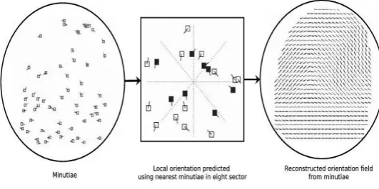
Fig-2: Minutiae based orientation field reconstruction.
4.2. MINUTIAE BASED :
[image:3.595.304.570.221.354.2]MINU-OFE : In this category, orientation Field is reconstructed directly from the minutiae alone [6]. Assume a blank image with the minutiae plotted on it. The n-fingerprint image is divided into non-overlapping blocks of 8x8 or 16x16 pixels. The foreground blocks are the ones with minutiae present in it. An orientation values is computed for each of such foreground block. Consider a line passing through the non-overlapping blocks (as shown in Figure 3.4 which divides the image into 8 equally spaced sectors. The local ridge orientation at each block is then predicted by using the nearest minutiae in each of the 8 sectors. The foreground region of interest is the region falling within the convex hull of minutiae.
Let M = {xi; yi;αi},1<= i<= N be the fingerprint minutiae
set consisting of N minutiae, where (xi; yi) is the spatial
location and αi the direction of the ith minutiae. The minutiae
direction αi is doubled to make αi equivalent to αi +Π . For K
© 2017, IRJET | Impact Factor value: 4.45 | ISO 9001:2008 Certified Journal
| Page 710
(4.1),
(4.2),
where is a weighting function. is taken as the
reciprocal of the euclidean distance between the block center and the ith minutiae. This makes the minutiae
direction dominate the ridge orientation of neighboring blocks. The orientation at block (m ,n) is computed as:
O(m,n)= arctan (4.3),
A reconstructed orientation field minutiae is depicted in Figure 3.4. The work by Feng and Jain [6] in reconstructing the fingerprint image from minutia sets alone, and successfully launching attacks against fingerprint recognition system indicates that the fidelity of the reconstructed OF to the actual OF is significant. Also, the performance of the algorithm in reconstructing the OF did not drop much even when only 60% of minutiae are only
available for OF reconstruction
.
4.3. FINGERPRINT IMAGE BASED:
IMAGE-OFE
:
orientation field estimated directly from the fingerprint image using gradient based approach[10].this is the most natural approach for extracting local orientations of the fingerprint image. The elementary orientations in the image are given by gradient i(x,y) which is atwo-dimensional vector [gx, gy] defined as:
(4.4),
where i represent the gray scale fingerprint image, gx and gy
are the derivatives of i at [x; y] with respect to the x and y direction respectively. the gradient phase angle denotes the direc-tion of the maximum change in pixel intensity. in principle, orientation eld is perpendicular to the gradient. the orientation image thus obtained is a dense orientation
image, i.e, orientation estimated for each pixel of the fingerprint image.
4.4.AVERAGED BASED :
AVG-OF :The average orientation field estimation is obtained by taking the average of both IMAGE-OFE and MINU-OFE.AVG- OFE is estimated using the technique proposed in [11] to average local gradients. Let θ ik and θ mk be the
orientation corresponding to K th block of IMAGE-OFE and
MINU-OF respectively. The average vector is given by
dk' = [avg cos k , avg sin k ] (4.4),
avg cos k = (4.5),
avg sin k = (4.6),
From this average vector dk',find the corresponding
orientation of the k th block of AVG-OF as
(4.7),
The double angle representation avoids any errors due to circularity of angles while averaging. Here, we assume ,
and are in radians. Out of these five different
techniques, MANUAL-OFE and DICT-OFE were used for latent fingerprints, whereas DICT-OFE, IMAGE-OFE , MINU-OFE and AVG-OFE were used for tenprints. All the OF estimated were of 16x16 block size. The region of interest for the fingerprint is considered to be the region inside the convex hull of the corresponding ideal minutiae of the fingerprint present in NIST-SD27.
5.RESULTS :
© 2017, IRJET | Impact Factor value: 4.45 | ISO 9001:2008 Certified Journal
| Page 711
incorporating our proposed hierarchical registration algorithm.
NIST-Bozorth3 is a minutiae based fingerprint matcher that is specially developed to deal with latent fingerprints. This matcher is part of the NIST Biometric Image Software (NBIS) [8],developed by NIST. MCC-SDK is a well known minutiae matchermore adapted to good quality fingerprints with reasonable number of minutiae in both query and reference templates. Both NIST-Bozorth3 and MCC-SDK are publicly available. We show the performance accuracy of the matcher using Cumulative Match Characteristic (CMC) curves.
5.1.EXPERIMENT1:CHOOSING THE BEST ORIENTATION FIELD FOR TENPRINTS
The Fig.3 shows the CMC curve of the NIST-Bozorth3 matcher when using MANUAL-OF for latent against various other OF estimation techniques for ten prints while performing pre-registration using our proposed hierarchical method. We can observe that the rank identification accuracy has a consistent improvement when AVG-OF is used for ten prints.
Fig-3: CMC curves showing rank identification rate for different OF estimation techniques.
The improvement while using AVG-OF is mainly because the image noise introduced in the estimation of IMG-OF is reduced while averaging with MINU-OF. Based on this result, we have chosen AVG-OF as the orientation field for ten prints in remaining experiments reported here.
5.2. EXPERIMENT 2: PRE-REGISTRATION
In this experiment, we perform pre-registration using our registration
Fig-4: Correlation based Registration
algorithm to reduce the minutiae search space of the ten print minutiae set, and then use the reduced minutiae set template as the reference template for the matcher.
© 2017, IRJET | Impact Factor value: 4.45 | ISO 9001:2008 Certified Journal
| Page 712
we observed a significant and consistent improvement in the rank identification accuracy for both the quality latents (good and bad ) category when incorporating the proposed pre-registration.
CONCLUSION :
We have proposed an orientation field based registration algorithm for partial fingerprints. The main objective of our paper is to improve the rank identification accuracy for poor quality latents. We were able to obtain consistent and significant improvement for bad quality category of latents from NIST-SD27.
Upon studying various orientation field estimation techniques for fingerprints to be used in our registration, we have noticed that the best representative orientation field for tenprints was obtained by averaging a gradient based orientation field estimated from the fingerprint image and the orientation field reconstructed from the minutiae set. This gave the best performance mainly due to noise reduction while averaging.
REFERENCES :
[1]. D. Maltoni, D. Maio, A. Jain, and S. Prabhakar. Handbook of Fingerprint Recognition. Springer Publishing Company, Incorporated, 2009.
[2]. P. Li, Y. Fu, U. Mohammed, J. Elder, and S. J. D. Prince. Probabilistic models for inference about identity. IEEE Transactions on Pattern Analysis and Machine Intelligence (PAMI), 34(1):144-157, 2010.
[3]. L. Liu, T. Jiang, J. Yang, and C. Zhu. Fingerprint registration by maximization of mutual information. IEEE Transactions on Image Processing, (5):1100-1110, 2006.
[4]. M. J. Saks and J. J. Koehler. The coming paradigm shift in forensic identification science. Science,
892- 895, 2005.
[5]. N. Yager and A. Amin. Fingerprint alignment using a two stage optimization. Pattern Recognition Letters, 317-324, 2006.
[6]. A. Jain and J. Feng. Latent Fingerprint Matching. IEEE Transactions on Pattern Analysis and Machine Intelligence, 33(1):88-100, 2011.
[7]. A. Jain and J. Feng. Latent Palmprint Matching. IEEE Trans. Pattern Analysis and Machine Intelligence, 31(6):1032-1047, 2009.
[8].NISTELFT,2013.URLhttp://www.nist.gov/itl/iad/ig/lat ent.cfm. Evaluation of latent fingerprint technologies. [9].NISTELFT1,2007.http://biometrics.nist.gov/csliks/latent
/elft07/phase1aggregate.pdf. Summaryof the results of Phase I ELFT testing.
[10]. D. Maltoni, D. Maio, A. Jain, and S. Prabhakar. Handbook of Fingerprint Recognition. Springer Publishing Company, Incorporated, 2009.
[11]. K. Nilsson and J. Bigun. Registration of fingerprints by complex filtering and by 1D projections of orientation images. Audio-and Video-Based Biometric Perso Authentication, Springer Berlin Heidelberg, pages 171-183,2005.