© 2017, IRJET | Impact Factor value: 5.181 | ISO 9001:2008 Certified Journal
| Page 96
IoT Based Smart Energy Meter
Birendrakumar Sahani
1, Tejashree Ravi
2, Akibjaved Tamboli
3, Ranjeet Pisal
41
Birendrakumar Sahani,
2Tejashree Ravi
3
Akibjaved Tamboli,
4Professor R.S. Pisal
Dept. of Electronics & Telecommunication Engineering, SPVP’s S.B. Patil College of Engineering, SPPU, Indapur ,
Pune – 413106, India
---***---Abstract -We can see a person standing in front of our
house from electricity board, whose duty is to read the energy meter and handover the bills to the owner of that house every month. This is nothing but meter reading. According to that reading we have to pay the bills. The main drawback of this system is that person has to go area by area and he has to read the meter of every house and handover the bills. Many times errors like extra bill amount, or notification from electric board even though the bills are paid are common errors. To overcome this drawback we have come up with an idea which will eliminate the third party between the consumer and service provider, even the errors will be overcome.
In this paper the idea of smart energy meter using IoT and Arduino have been introduced. In this method we are using Arduino because it is energy efficient i.e. it consume less power, it is fastest and has two UARTS. In this paper, energy meters which is already installed at our houses are not replaced, but a small modification on the already installed meters can change the existing meters into smart meters. The use of GSM module provides a feature of notification through SMS. One can easily access the meter working through web page that we designed. Current reading with cost can be seen on web page. Automatic ON & OFF of meter is possible. Threshold value setting and sending of notification is the additional task that we are performing)
Key Words: Smart Energy Meter, Electric board,
UARTS, IoT, GSM, Wi-Fi, webpage.
1. INTRODUCTION
In the present billing system the distribution companies are unable to keep track of the changing maximum demand of consumers. The consumer is facing problems like receiving due bills for bills that have already been paid as well as poor reliability of electricity supply and quality even if bills are paid regularly. The remedy for all these problems is to keep track of the consumers load on timely basis, which will held to assure accurate billing, track maximum demand and to detect threshold value. These are all the features to be taken into account for designing an efficient energy billing system. The present project “IoT Based Smart Energy Meter” addresses the problems faced by both the consumers and the
distribution companies. The paper mainly deals with smart energy meter, which utilizes the features of embedded systems i.e. combination of hardware and software in order to implement desired functionality. The paper discusses comparison of Arduino and other controllers, and the application of GSM and Wi-Fi modems to introduce ‘Smart’ concept. With the use of GSM modem the consumer as well as service provider will get the used energy reading with the respective amount, Consumers will even get notification in the form text through GSM when they are about to reach their threshold value, that they have set. Also with the help of Wi-Fi modem the consumer can monitor his consumed reading and can set the threshold value through webpage.
This system enables the electricity department to read the meter readings monthly without a person visiting each house. This can be achieved by the use of Arduino unit that continuously monitor and records the energy meter reading in its permanent (non-volatile) memory location.This system continuously records the reading and the live meter reading can be displayed on webpage to the consumer on request. This system also can be used to disconnect the power supply of the house when needed.
[image:1.595.307.575.486.714.2]2. ARCHITECHURAL MODEL
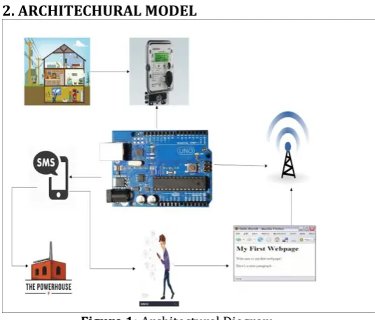
Figure 1:
Architectural Diagram
© 2017, IRJET | Impact Factor value: 5.181 | ISO 9001:2008 Certified Journal
| Page 97
When the various appliances of the householdconsume energy the energy meter reads the reading continuously and this consumed load can be seen on meter.
We can see that the LED on meter continuously blinks which counts the meter reading. Based on
The blinking, the units are counted. Normally, 3200 blinks is one unit.
In our project we are trying to develop, a system in which Arduino Uno act as main controller, which continuously monitor energy meter. As per the blinking of LED on energy meter the
Arduino will measure the unit consumption. The measured reading with the calculation of
the cost will be continuously displayed on web page that we have designed.
Threshold value can be set on webpage with the help of Wi-Fi, as per the consumer’s requirement. When the consumers reading will be near about to the set threshold value it will send a notification value to the consumer. This threshold value notification will increase
the awareness amongst the consumer about the energy.
When the consumer gets the notification he can visit the webpage and change the threshold value.
If the consumer is not aware with the threshold notification, then the meter will automatically get off. Then the consumer has to visit the webpage again and increment the threshold value. By the incrementation, the meter will automatically get ON.
Finally the overall monthly bill with cost will be sent to customer as well as service provider in the form of text at first day of every month.
3. EASE OF USE
[image:2.595.306.569.134.364.2]BLOCK DIAGRAM
Figure 2:
Block Diagram Representation
The above block diagram represents our proposed ‘IoT BASED SMART ENERGY METER’ system:
3.1 ENERGY METER:
Energy meter or watt-hour meter is an electrical instrument that measures the amount of electrical energy used by the consumers. Utilities is one of the electrical departments, which install these instruments at every place like homes, industries, organizations, commercial buildings to charge for the electricity consumption by loads such as lights, fans, refrigerators and other home appliances. Energy meter measures the rapid voltage and currents, calculate their product and give instantaneous power. This power is integrated over a time interval, which gives the energy utilized over that time period.
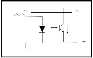
3.2 SIGNAL CONDITIONER (P817):
[image:2.595.362.522.621.720.2]
© 2017, IRJET | Impact Factor value: 5.181 | ISO 9001:2008 Certified Journal
| Page 98
Above figure shown is the simple internal working ofopto-coupler P817 which we are using as signal conditioning block. As we can see on a working meter that one LED continuously blinks, it is nothing but indicates the count of power. The LED whenever blinks it produces only 0.7v which is not suitable for Arduino board to capture, so to remove this error we are using this block.
When the LED blinks the diode will conduct, transistor will get active and it will give 5v at output which we are externally giving to transistor. Whenever LED will blink the 5v supply will be provided to Arduino board and it will count them. We are using signal conditioning block to increase voltage.
3.3 ARDUINO UNO(ATMEGA 328):
Arduino board is the heart of our system. Entire functioning of system depends on this board. Arduino reacts to the 5v supply given by opto-coupler and keeps on counting the supply and then calculates the power consumed and also the cost. This data, it continuously stores on webpage, so that users can visit any time and check their consumption. It even reacts accordingly as per programed, to the situations like message sending during threshold value etc.
3.4 MAX 232:
We are using MAX 232 for serial communication with the components that are GSM module and Wi-Fi module MAX232 is used to provide TTL to the components as per the requirement. GSM needs TTL so it is connected to Arduino through MAX232. Some Wi-Fi module doesn’t require TTL because it’s already build in it and some may require based on its working.
3.5 GSM MODULE (SIM900):
GSM stands for Global System for Mobile communication. It is widely used mobile communication modem system in the world. GSM is an open and digital cellular technology used for transmitting mobile voice and data services operates at the 850MHZ, 900MHZ, 1800MHZ, 1900MHZ frequency bands. It has ability to carry 64kbps to 120Mbps of data rates.
In our system GSM is used to send the notification of threshold reaching to consumer and for sending message of total consumption of unit with cost to the service provider and consumer.
3.6 Wi-Fi MODULE (ESP8266):
Wi-Fi stands for Wireless Fidelity. We are using Wi-Fi
which acts as heart for IoT. Through Wi-Fi the consumer can set changes in threshold value, he can ON and OFF the energy meter. Time to time the readings of units and cost are displayed on webpage. Consumer can accesses the Arduino board and meter with help of Wi-Fi.3.7 WEBPAGE (HTML):
We designed webpage for operating Arduino and Energy Meter with the help of HTML. HTML stands for Hypertext Markup Language. It is a standard markup language for creating web pages and web applications with Cascading Style Sheets (CSS) and JAVA scripts it forms a triad of cornerstone technologies for World Wide Web. Web browser receives HTML documents from a Webserver or from local storage and render them into multimedia web pages.
HTML describes the structure of web page semantically and originally included cues for the appearance of the document. HTML elements are the building blocks of HTML pages.
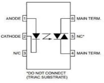
[image:3.595.337.513.469.610.2]3.8 DRIVER CIRCUIT (moc3071):
Figure 4:
Driver Circuit
It is a 6 pin device known as opto coupler or opto isolator.
In our project we are using this opto coupler to cut off the AC load.
© 2017, IRJET | Impact Factor value: 5.181 | ISO 9001:2008 Certified Journal
| Page 99
3.9 SWITCHING DEVICE:In our system we are using SSR as switching device even
though we can use RELAY because SSR is highly advantageous. We are using switching device to switch the energy meter. For ON and OFF purpose of meter we are using switching block. SSR stands for SOLID STATE RELAY.Why SSR instead of RELAY?
Both are used as AC switching device, but if switching speed is high than SSR is suitable, if switching speed is slow than RELAY is used. Relay life decreases as number of usage time
increases, but in SSR there is no change.
For driving RELAY, current or power required is more comparatively to SSR.
For switching SSR requires 15amp, whereas RELAY needs (30amp,50amp,90amp) as per requirement.
4. ABBREVIATION USED
IoT - Internet of Things
LED - Light Emitting Diode.
GSM - Global System for Mobile
Wi-Fi - Wireless Fidelity
HTML - Hyper-Text Markup Language
CSS - Cascading Style Sheets
5. EQUATIONS AND MATHEMATICAL
CALCULATION:
Our system does not contain very vast and difficult calculations.
Usually different meters have different readings.
Some have,
1500 blinks = 1 unit
Mostly, 3200 blinks = 1 unit depends on manufacturer.
In our case 3200 blinks of LED is 1 unit. But for practical purpose,
Assumption we made in our system,
5 blinks = 1 unit of power consumption.
Let, X = number of blinks of LED
Y = number of units of electricity.
Z = cost of consumption.
Basically,
No. of units (Y) = (X/3200)
But in our case,
Y = (X/5)
Assume that 1 unit cost = 5rs.
Z = Y * 5rs
For Threshold,
Assumed threshold set value will be = 5 units for practical.
If units reach,
Threshold value – 1 unit = 5-1 = 4 units,
Notification will be send to consumer, if consumer doesn’t react and increase the threshold value then meter will automatically get OFF.
Again to turn it ON consumer has to visit webpage again to increase threshold value.
For practical purpose increment and decrement of threshold can be done by +5units or -5units.
5.1 UNIT:
Normally, basic unit of electricity is Kilowatt hour
(KWh).
1kWh = 1000 watt for 1 hour.
Example,
© 2017, IRJET | Impact Factor value: 5.181 | ISO 9001:2008 Certified Journal
| Page 100
[image:5.595.344.520.117.269.2]6. OVERVIEW OF INTERNET OF THINGS
Figure 5: IoT Representation
The IoT allows objects to be sensed or controlled remotely
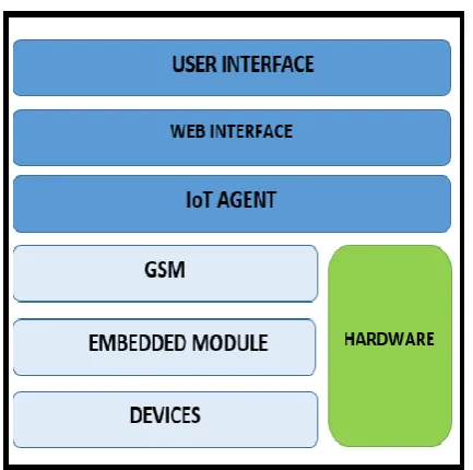
across existing network infrastructure, creating opportunities for more direct integration of the physical world into computer-based systems, and resulting in improved efficiency, accuracy and economic benefit in addition to reduced human intervention. When IoT is augmented with sensors and actuators, the technology becomes an instance of the more general class of cyber-physical system, which also encompasses technologies such as smart grids, virtual power plants, smart homes and smart cities. Each thing is uniquely identified through its embedded computing system but is able to interoperate within the existing internet infrastructure [image:5.595.79.243.136.321.2]Figure 6: Interfacing of Hardware
Figure 7: IoT Working
People also want to communicate with all non-living things through internet such as home appliances, furniture’s, stationeries, cloths etc. The people already have a lot of technologies to interact with living things but IoT enables to communicate with non-living things with comfort manner. IoT is a convergence of several technologies like ubiquitous, pervasive computing, Ambient Intelligence, Sensors, Actuators, Communications technologies, Internet Technologies, Embedded systems etc.
7. Why ARDUINO board than other controller?
Well known, controllers to us are 8051, pic 16f/18f,
ARM7, msp430, other latest boards like Intel Galileo Gen 2 etc. Out of all these ARDUINO is the best. We require two UARTS, but pic 16f/18f and 8051 has only one UART.
Whereas ARDUINO has two UARTS as required, one in hardware and other in software.
Msp430 has 3 UARTS but it is very costly than ARDUINO.
ARDUINO is even less in cost as compared to other controller.
Other boards like Intel Galileo gen 2 are very very costly and complex to handle.
The best part of Arduino usage is that its programming is very easy as compared to other devices.
For the new start by students it’s very feasible and easy to use.
8. RESULT
[image:5.595.52.269.503.718.2]© 2017, IRJET | Impact Factor value: 5.181 | ISO 9001:2008 Certified Journal
| Page 101
2] When threshold is about to over the following messagewill be sent to consumer.
3] Monthly consumption of power will be send as message to the consumer with total bill of electricity.
4] The monthly bill with unit consumption and user Id will be sent to service provider.
9. CONCLUSIONS
An attempt has been made to make a practical model of ‘IoT Based Smart Energy Meter.’ The propagated model is used to calculate the energy consumption of the
household, and even make the energy unit reading to be handy.
Hence it reduces the wastage of energy and bring awareness among all. Even it will deduct the manual intervention.
ACKNOWLEDGEMENT
It gives us great pleasure in presenting the paper on “IoT Based Smart Energy Meter”. We would like to take this opportunity to thank our internal guide of Electronics And Telecommunication Engineering Department, SBPCOE, Indapur Prof. R. S. Pisal for giving us all the help and guidance we needed. We are really grateful to them for their kind support. Their valuable suggestions were very helpful. We are also grateful to Prof. P. R. Taware, project coordinator, Electronics And Telecommunication Engineering Department, SBPCOE, Indapur for his indispensable support and suggestions.
REFERENCES
[1] Himshekhar Das, L.C.Saikia, “GSM Enabled Smart Energy
Meter and Automation of Home Appliances”, PP-978-1-4678-6503-1, 2015 IEEE.
[2] Ofoegbu Osita Edward, “An Energy Meter Reader with
Load Control Capacity and Secure Switching Using a Password Based Relay Circuit”, PP-978-1-4799-8311-7, ‘ Annual Global Online Conference on Information and Computer Technology’, IEEE 2014.
[3] Yingying Cheng, Huaxiao Yang, Ji Xiao, Xingzhe Hou,
“Running State Evaluation Of Electric Energy Meter”, PP-978-1-4799-4565-8, ‘Workshop on Electronics, Computer and Applications’, IEEE 2014.
[4] Sahana M N, Anjana S, Ankith S,K Natarajan, K R Shobha,
© 2017, IRJET | Impact Factor value: 5.181 | ISO 9001:2008 Certified Journal
| Page 102
[5] Luigi Martirano,Matteo Manganelli,Danilo
Sbordone,‘‘Design and classification of smart metering systems for the energy diagnosis of buildings’’ IEEE 2015.
[6] J. Widmer, Landis,” Billing metering using sampled
values according lEe 61850-9-2 for substations”,IEEE 2014.
[7] Cheng Pang,Valierry Vyatkin,Yinbai Deng, Majidi
Sorouri, “Virtual smart metering in automation and simulation of energy efficient lightning system” IEEE 2013.
[8] Amit Bhimte, Rohit K.Mathew, Kumaravel S,
“Development of smart energy meter in labview for power distribution systems”, “IEEE INDICON 2015 1570186881”, 2015.
[9] H. Arasteh, V. Hosseinnezhad, V.Loia, A.Tommasetti,
O.Troisi, M.Shafie Khan, P.Siano, “IoT Based Smart Cities: A survey”IEEE 978-1-5090-2320-2/1631.00,2016.
[10] Clement N. NYIRENDRE, Irvine NYANDOWE, Linda
SHITUMBAPO, “A comparison of the collection tree protocol (CTP) and AODV routing protocol for a smart water metering.”, PP NO. 1-8,2016.
BIOGRAPHIES
Name: Sahani Birendrakumar B.E Electronics &Telecomm. Engg. S.B. Patil College of Engineering E-mail_id:
Name: Ravi Tejashree
B.E Electronics &Telecomm. Engg. S.B. Patil College of Engineering E-mail_id:
Name: Tamboli Akibjaved B.E Electronics &Telecomm. Engg. S.B. Patil College of Engineering E-mail_id: