ISSN(Online): 2320-9801
ISSN (Print) : 2320-9798
I
nternational
J
ournal of
I
nnovative
R
esearch in
C
omputer
and
C
ommunication
E
ngineering
(An ISO 3297: 2007 Certified Organization)
Vol. 4, Issue 3, March 2016
Design of Multiband CPW Fed Inverted
Trapezoidal Monopole Antenna for UWB
Applications
G.Usha Jyothi1, K. Prasanna Kumar2, K.Anand3, D.Dhanalakshmi4
Department of Electronics and Communication Engineering, Lendi Institute of Engineering and Technology, Jonnada,
Vizianagaram ,J.N.T.U.Kakinda University, Andhra Pradesh, India
ABSTRACT: This paper presents the design and simulation of rectangular microstrip antenna with multi band trapezoidal monopole antenna for wireless communications with frequency standards 2.4GHZ to 8.8GHZ. The shape will provide the three bandwidths of 0.2584 is obtained from range 2.4GHZ to 2.6GHZ and 0.3035 is obtained from range 3.8GHZ to 4.1GHZ and maximum bandwidth is 0.7607 from ranges are 8.6 GHZ to 9.4GHZ and the center frequencies of three bands at 2.6,4.0 and 8.6 GHZ. The antenna design is an improvement from previous research with inverted trapezoidal slots and it is simulated .The gain of the antenna is 4.4173dB and VSWR and reflection coefficients are measured. The parametric study, by varying different dimensions and parameters, is done and the simulated results of S-parameters, VSWR, radiation pattern and gain are plotted.
KEYWORDS: Microstrip patch anenna; Monopole antenna; Multiple band notches; UWB antenna, inverted trapezoidal antenna; CPW feeding.
I. INTRODUCTION
Micro strip patch antennas consists of a very thin metallic strip (patch) on a grounded substrate found extensive applications in different fields due to their attractive feature. These antennas are low profile low weight, low cost, compact and comfortable structure and easy to fabricate. These antennas have drawn attentions of scientific community over the past decades. These antennas have drawn attentions of scientific community over the past decades. These antennas can be easily put on any surfaces and may be easily coupled with MIC components. However the low gain values and bandwidth constraints limit their usage in commercial applications. Microstrip antennas are characterized by a larger number of physical parameters than conventional microwave antennas. They can be designed to have many geometrical shapes and but rectangular and circular micro strip resonant patches have been used extensively in many applications.
Nowadays scientific community is deeply involved in improving their performance so that there may replace other antennas structures in modern communication systems. In the present communication we have presented a rectangular patch micro strip antenna with U-shaped slot using CPW feeding technique. The simulation analysis of this antenna is carried out on An soft high frequency structured simulation software(HFSS).
ISSN(Online): 2320-9801
ISSN (Print) : 2320-9798
I
nternational
J
ournal of
I
nnovative
R
esearch in
C
omputer
and
C
ommunication
E
ngineering
(An ISO 3297: 2007 Certified Organization)
Vol. 4, Issue 3, March 2016
experimentally. It will be demonstrated that the optimal design of this type of antenna can achieve an ultra wide bandwidth with satisfactory radiation patterns.
With the definition and acceptance of the ultrawide-band (UWB) impulse radio technology in the USA [3],there has been considerable research effort put into UWB radio technology worldwide. However, the nondigital part of a UWB system, i.e., transmitting/receiving antennas, remains a particularly challenging topic.
A suitable UWB antenna should be capable of operating over an ultra wide bandwidth as allocated by the Federal Communications Commission. At the same time, reasonable efficiency and satisfactory radiation properties over the entire frequency range are also necessary. Another primary requirement of the UWB antenna is a good time domain performance, i.e., a good impulse response with minimal distortion [2].
II.RELATED WORK
In [1] author use a compact ultra wideband monopole antenna fed by CPW and microstrip line with triple band-rejection characteristics are presented and discussed. A simple triple band band-rejection structure using broken ∩-slot is presented. By transforming the CPW feed to microstrip, the bandwidth and radiation characteristics are preserved. We achieved a reduction in size compared to the antennas presented in [2-6].And the bandwidth ,Gain is improved by replacing the shape of microstrip patch antenna by inserting the more slots inside the rectangular patch in the shape of inverted trapezoidal microstrip patch antenna and so many parametric study is done in order to increase the bandwidth and gain of the antenna by changing the length and width of the slots (L3,L4).Future Challenges of a microstip patch antenna are bandwidth extension techniques,control of radiation patterns,reducing losses,improving feed networks.In order to increase the directivity of the microstrip antennas triple multiple microstrip radiators are used to cascade to form an array
III. ANTENNA GEOMETRY
The geometry of the suggested antenna is shown in the figure above. The prototype antenna consists of a substrate on which ground is mounted..
In the design, FR4 of dielectric constant (εr) 4.4 is used as the primary material of the substrate. The dimensions
of substrate are 40mm× 12mm and the thickness of 0.8mm, having a loss tangent of 0.02 is designed using standard equations. The rectangular micro strip of 24mm long (Lf) and 4.8mm (Wf) and gap of distance 0.3mm between the
signal strip and the finite coplanar rectangular ground plane is depicted in Fig above .The feed of antenna that fabricated on a FR4 epoxy substrate with thickness of 0.8mm and relative permittivity (εr) of 4.4 .In this design we
have taken four notches the length of four slots(L1,L2,L3,L4) are 22.8,20.4,18,5.2.The use of low cost FR4 has a substrate introduces some additional complexity on the antenna design .This antenna design is due to the in accuracy of the FR4 relative permittivity and its high loss tangent.
IV. PARAMETRIC STUDY
ISSN(Online): 2320-9801
ISSN (Print) : 2320-9798
I
nternational
J
ournal of
I
nnovative
R
esearch in
C
omputer
and
C
ommunication
E
ngineering
(An ISO 3297: 2007 Certified Organization)
Vol. 4, Issue 3, March 2016
Fig.1. Plot of reflection coefficient with respect to variations in length (L4)
The figure.1 below shows the simulated graphs of impedance bandwidth of the patch antenna by varying the length (L4) of antenna. The changes of impedance bandwidth and radiation pattern are also studied by varying the length (L4) of patch. It indicates the changes in the resultant plot of patch are varied from 5.2mm to 5.8mm.Figure 2 shows the plot of VSWR of patch when length is varied from 5.2mm to 5.8mm.
Fig.2 Plot of VSWR with respect to variations in length(L4) -40
-35 -30 -25 -20 -15 -10 -5 0
0 2 4 6 8 10 12 14
L4=4mm
L4=5.2mm
L4=5.4mm
L4=5.6mm
S(
1
,1
)
in
d
B
ISSN(Online): 2320-9801
ISSN (Print) : 2320-9798
I
nternational
J
ournal of
I
nnovative
R
esearch in
C
omputer
and
C
ommunication
E
ngineering
(An ISO 3297: 2007 Certified Organization)
Vol. 4, Issue 3, March 2016
The figure 3 below shows the simulated graphs of impedance of the patch by varying the length(L3) of antenna changes from 13.8mm to 15.4mm.
Fig.3. Plot of reflection coefficient with respect to length(L3)
It is noted that optimum bandwidth is obtained when length is 15mm.The figure 4 shows the VSWR plot of the patch which identifies the operating frequency of the patch antenna by varying the length(L3) of the design.
F
ISSN(Online): 2320-9801
ISSN (Print) : 2320-9798
I
nternational
J
ournal of
I
nnovative
R
esearch in
C
omputer
and
C
ommunication
E
ngineering
(An ISO 3297: 2007 Certified Organization)
Vol. 4, Issue 3, March 2016
The changes of impedance bandwidth and VSWR are also studied by varying the length(L3) of the patch is observed and the figure 4 is used to indicate these plots.
V. OPTIMIZED DESIGN
On the basis of the detailed study of the plots and other results obtained in the parametric study, the optimized dimensions for the antenna design is decided and experimentally validated and verified. The design parameters are optimized such that they provide maximum bandwidth and gain.
The details of the optimized parameters are as described below. Based on the detailed parametric studies, the optimum dimensions obtained for the antenna are L1=22.8mm, L2=20.4mm, L3=18mm, L4=5.2mm. The figures above show the plots of optimized antenna.
Fig. 5 shows the radiation pattern in E-plane of proposed optimized antenna
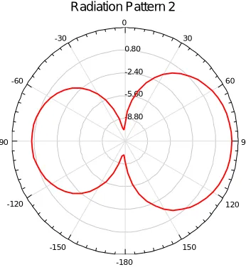
Fig. 6 shows the radiation pattern of the proposed optimized antenna design in the H-plane.
It is observed that the antenna gives a maximum bandwidth of 0.7607dB. And shows the radiation pattern of the proposed antenna and 4.4173dB gives the gain obtained from the optimized design.
-13.50 -9.50 -5.50 -1.50 90 60 30 0 -30 -60 -90 -120 -150 -180 150 120 HFSSDesign1
Radiation Pattern 1 ANSOFT
Curve Inf o dB(GainTotal) Setup1 : LastAdaptive Freq='7GHz' Phi='0deg' -8.80 -5.60 -2.40 0.80 90 60 30 0 -30 -60 -90 -120 -150 -180 150 120 HFSSDesign1
Radiation Pattern 2 ANSOFT
ISSN(Online): 2320-9801
ISSN (Print) : 2320-9798
I
nternational
J
ournal of
I
nnovative
R
esearch in
C
omputer
and
C
ommunication
E
ngineering
(An ISO 3297: 2007 Certified Organization)
Vol. 4, Issue 3, March 2016
Fig.7 shows the 3-dimensional radiation pattern of the proposed antenna design in its optimum dimensions
Fig7. 3-D Polar plot of radiation pattern of optimized antenna
VI. CONCLUSION AND FUTURE WORK
A ultra wideband monopole antenna fed by CPW and microstrip line with triple band-rejection characteristics are presented and discussed. A simple triple band rejection structure using inverted trapezoidal shape is presented. By transforming the CPW feed to microstrip, the bandwidth and radiation characteristics are preserved. The effects of the various geometrical parameters on the antenna performance are studied. The experimental results show that the realized antenna with a very compact size and relatively good radiation characteristics has a wide bandwidth from 2.4 to 8.8GHz with triple controllable notched bands centered at 2.4,4,8.6GHz.Future challenges of a microstrip antenna are Bandwidth Extension Techniques,Control of Radiation Patterns,Reducing Losses,improving Feed network,Size reduction techniques.In order to increase the directivity of the microstrip antennas triple multiple microstrip radiators are used to cascade to form an array.
REFERENCES
[1]Verbiest JR, Vandenbosch GAE. A novel small-size printed tapered monopole antenna for UWBWBAN. IEEE Antenna Wireless Propag Lett 2006;5:377–9.
[2] Liang J, Chiau CC, Chen X, Parini CG. Study of a printed circular disc monopole antenna for UWB systems. IEEE Trans Antennas Propag 2005;53:3500–4.
[3] Jilkova J, Radia Z. Ultra-wideband coplanar-fed monopoles: a comparative study. Radio Eng 2007:17.
[4] Kim J, Yoon T, Kim J, Choi J. Design of an ultra wide-band printed monopole antenna using FDTD and genetic algorithm. IEEE Microw Wireless Comp Lett
2005;15:395–7.
[5] Cho YJ, Kim KH, Choi DH, Lee SS, Park S-O. A miniature UWB planar monopole antenna with 5-GHz band-rejection filter and the time-domain characteristics.
IEEE Trans Antennas Propag 2006;54: 1453–60.
[6] Vuong TP, Ghiotto A, Duroc Y, Tedjini S. Design and characteristics of a small U-slotted planar antenna for IR-UWB. Microw Opt Technol Lett 2007;49:
1727–31.
[7] Abbosh AM, Bialkowski ME,Mazierska J, Jacob MV. A planar UWBantenna with signal rejection capability in the 4–6GHz band. IEEE Microw Wireless Comp
Lett 2006;16:278–80.