http://dx.doi.org/10.4236/jamp.2014.212130
How to cite this paper: Zhao, K., Yi, B.K. and Wang, Z.F. (2014) Fiber-Loop Ringdown Multi-Function Sensors. Journal of Applied Mathematics and Physics, 2, 1118-1122. http://dx.doi.org/10.4236/jamp.2014.212130
Fiber-Loop Ringdown Multi-Function
Sensors
Ke Zhao, Bokai Yi, Zefeng Wang
*College of Optoelectronic Science and Engineering, National University of Defense Technology, Changsha, China
Email: *[email protected]
Received October 2014
Abstract
We demonstrate a fiber-loop ring down multi-function sensors system, which can be used to measure refractive index and curvature simultaneously. Good agreement has been found between theoretical analyses and experimental results. It has great potential for sensor applications.
Keywords
Fiber-Loop Ringdown, Multi-Function Sensors, Refractive Index Sensors, Curvature Sensors
1. Introduction
Optical fiber sensors are widely applied due to its advantages of low cost, light weight, flexible structure design and not being affected by electromagnetism. According to sensing principle, optical fiber sensors can be divided into intensity-based ones, interferometric sensors, polarization sensors, grating sensors and so on [1]. Among them, intensity-based sensors enjoy the most simply structure and thus were widely studied in the past. However, the application of conventional intensity-based sensors is with limitation due to its low sensitivity and poor per-formance towards the source light power fluctuations. Optical fiber Loop Ring down (FLRD), originating from the traditional CRD technology, is a new intensity-based sensing technology [2]-[6]. FLRD connects two optical couplers into an optical ring and probes external influence on the transmission loss by measuring the ring down time. As no optical amplification is needed, no ASE noise will be introduced. That’s why FLRD manages to be highly accurate, sensitive, fast-responding and free from light power fluctuations at the same time [2]. Apart from that, FLRD presents pleasing flexibility in application: by equipping with different sensors, it can sense various parameters such as pressure, temperature, strain, refractivity and so on. Currently the studies of optical fiber sensors based on FLRD mainly focuses on measurements for a single physical parameter, few about mul-ti-function sensing system [3]. In this paper, we demonstrate a fiber-loop ring down mulmul-ti-function sensors sys-tem, which includes a refractive index sensor and a curvature sensor. The experimental results are in well agreement with the theoretical analyses, which testifies the feasibility of FLRD used for multi-function mea-surements.
2. Experimental Setup
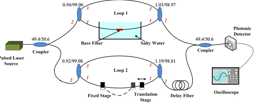
The experimental setup of our FLRD multi-function sensors is depicted in Figure 1. The input and output fibers are connected to a loop with 1550 nm single-mode couplers with the splitting ratio of 99:1. We sign the input ends as end 1(99%), end 2(1%) and the output end as end 3. The light coming from a nanosecond pulse fiber laser is averaged into each fiber loop through a multi-coupler and about 50% of the input light is coupled into each fiber loop. For each round loop, 99% of the light will remain travelling in the loop, and the rest 1% is exported to the coupler. To observe the ringdown waves separately, we splice the time delay fiber between the output multi-coupler and the second loop. The output light is injected to the In GaAs near infrared detector (signal: DC400FC, response speed: 0.1ns, bandwidth: 2.0 GHz) and monitored by an oscilloscope (model: TDS7154, bandwidth: 1.5 GHz, sampling rate: 25 GS/s).
As Figure 1 shows, we design and manufacture the sensor head of loop 1: first we remove the plastic coating layer, and then wear off part of the cladding, and also we fix the bare fiber on a glass plate to prevent snapping. The curvature sensor structure of loop 2 is designed as: part of the fiber loop is used as the sensor head with one end fixed and the other end movable.
3. Results and Discussion
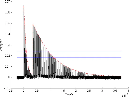
The output signal in time-domain of the multi-function sensor system is shown in Figure 2. When the pulse width is far less than the interval of two adjacent pulses, it will not influence the detection results; while when the pulse width is the same as or larger than interval, the peak position and the pulse shape will change. Theo-retically, the adjacent pulse interval is the time of light travelling one round, which is much longer than the width of the input laser pulses in our experiments.
The cavity length of the first loop is measured to be 5.3 m, the second one is 7.4 m, and the length of the de-lay fiber is 70 m. Taking the refraction index of the fiber core n = 1.45 into consideration, the pulse width of loop1 is calculated to be 26 ns, while the second one is 36ns. From the figure, it can be calculated that the first loop’s internal of adjacent pluses is 25.69 ns, and the second loop is 35.98 ns. The delay time in the two loops as can be seen from the figure is 341.7 ns, and the length of the delay fiber is calculated to be 70.7 m. As can be seen, the experimental results correspond well with the theoretical analyses. The sensing principle of the FLRD system is to get the information of loss by measuring the decay time, and then obtain the physical quantity of external effects. So we measure the intrinsic ringdown time first. We get the intrinsic decay time from Figure 2
that , and the total fiber transmission loss per round trip can be figured out to be:
, according to the equation .
3.1. Refractive Index Sensor
[image:2.595.95.538.525.704.2]Light propagation in the optical fiber is based on the principle of total internal refraction, while part of light still
Figure 2. The signal in time-domain of the multi-function sensor system.
transmits to the cladding, and decays exponentially along the radial direction at its boundary, as shown in
Figure 3. This part of light is the so-called evanescent wave. Based on the evanescent-field mechanism, we can design the refractive index sensor. By changing the fiber cladding to other materials (gases, liquids), there will be an additional transmission loss, which can be used to calculate the refractive index of the material surround-ing the bare fiber.
In our experiments, we put the sensor head structure in the liquid of clear water and different concentrations of NaCl solution, and we test and analyze the law of the ring down time changing with the refraction index. The experimental results of three times are shown in Table 1. From Table 1, it can be seen that the decay time in-creases with the increase of the refraction index around the sensor head, which is in agreement with the results in reference [4].
3.2. Curvature Sensor
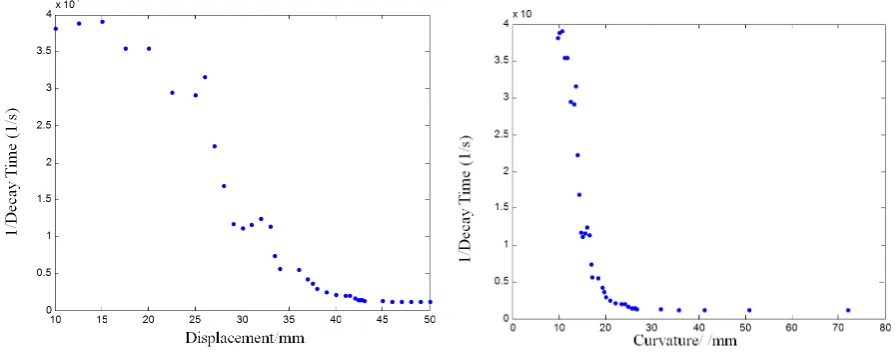
Based on the micro-bend loss mechanism, if the curvature is larger than a threshold value, the additional loss will increases exponentially with the increasing of curvature. We measure the curvature loss by changing the displacement of the two stages, as shown in Figure 4.
According to Figure 4, the length of the curve between two stages can be described as,
R L
θ⋅ = (1)
(
)
sin θ 2 =x 2R (2)
From Equations (5) and (6), we can get,
(
)
2 sinR L 2R =x (3)
As the classical theoretical model of signal fiber describes, the curvature loss is monotonously decreasing with the bending radius. In our experiment, we test and verify this law. As Figure 5 shows, the result of experi-ment corresponds with the theoretical anticipation.
4. Conclusion
Figure 3. The schematic of the refractive index sensor head.
Table 1. Ringdown time of different refraction index medium.
Medias Decay time(s)
One Two Three
Air 6.3258 × 10⁻⁸ 6.3963 × 10⁻⁸ 6.2289 × 10⁻⁸
Clear water 8.9686 × 10⁻⁸ 9.0059 × 10⁻⁸ 8.9731 × 10⁻⁸
Salty water 1.1558 × 10⁻⁷ 1.1272 × 10⁻⁷ 1.1532 × 10⁻⁷
R
x
L
Translation Stage Fixed Stage
[image:4.595.168.458.192.371.2]θ
Figure 4. The schematic diagram of the curvature sensor head.
Figure 5. The result diagram of the curvature sensor.
Acknowledgements
This work was supported by the Projects of National Natural Science Foundation of China under Grant No. 11274385.
References
[1] Kersey, A.D. (1996) A Review of Recent Development of Fiber Optic Sensor Technology.Optical Fiber Technology, 2, 291-296. http://dx.doi.org/10.1006/ofte.1996.0036
[image:4.595.89.537.405.581.2]http://dx.doi.org/10.1364/OL.29.000352
[3] Wang, C.J. (2009) Fiber Loop Ringdown—A Time-Domain Sensing Technique for Multi-Function Fiber Optic Sensor Platforms: Current Status and Design Perspectives. Sensors, 9, 7595-7621. http://dx.doi.org/10.3390/s91007595
[4] Wang, C.J. and Herath, C. (2010) High-Sensitivity Fiber-Loop Ringdown Evanescent-Field Index Sensors Using Sin-gle-Mode Fiber. Optics Letters, 35, 1629-1631. http://dx.doi.org/10.1364/OL.35.001629
[5] Wang, Z.F., Jiang, M., Xu, H.Y. and Du, R. (2011) New Optical Fiber Micro-Bend Pressure Sensors Based on Fi-ber-Loop Ringdown. Elsevier Ltd.