http://dx.doi.org/10.4236/jpee.2014.24050
Microgrid Design Including Fuzzy Logic
Controlled Storage System
Yaser Soliman Qudaih, Raheel Ali, Yasunori Mitani
Department of Electrical Engineering and Electronics, Kyushu Institute of Technology, Kitakyushu, Japan Email: [email protected], [email protected]
Received December 2013
Abstract
Smart grid design and structures are somehow depending on the way of designing and operating Microgrids. In this research a unique design of microgrid is proposed as in medium tension iso-lated power distribution system contains diesel generation unit and photovoltaic generation. Sto-rage system is a part of the control strategy to reduce the diesel usage and to maintain the balance between generation and demand which might be disturbed due to the presence of PV system. Fuzzy logic control scheme has been chosen compared with conventional controller to be the main controller for both the diesel unit and storage system. Promising result has been found by digital simulation using Matlab Simulink proving the possibility of reducing the dependency on fossil fu-eled generators and increase the utilization of renewable energy.
Keywords
Microgrid; Fuzzy Logic Control; Electric Storage Systems
1. Introduction
Continuous studies and researches are going on to have the optimum utilization of renewable energy into elec-tric grid. Aggregated wind turbine generators on a large scale are penetrating the utility grids through transmis-sion lines and became a kind of centralized power generation [1] [2]. Also, huge utilization of solar generation system is penetrating the grid in the same manner [3] [4]. However, microgids in the distribution level of the electric grid also contain renewable energy generation of smaller scale. Microgrids are more sophisticated than other conventional isolated power systems [5].
With the rapid increase of dispersed sources such as diesel generation, fuel cells and renewable energy tech-nology, the need of considering practical solutions to adapt the big changes in the grid structure became more urgent. In this regard, conventional controllers are no more efficient to adapt the changes and the researchers turned more strongly in applying intelligent controllers to solve the related issues [6] [7].
In this research, a medium voltage level isolated power distribution system is designed using Matlab Simulink environment to investigate the viability of having a relatively big scale penetration of PV generation system. However, the main target of this research is to reduce the dependency on fossil fueled generators and increase the utilization of renewable energy. The method used in this paper is based on digital simulation to have the smallest possible size of storage systems and to maintain the balance between generation and demand. Fuzzy logic control scheme has been chosen compared with conventional controller to be the main controller for both the diesel unit and storage system. Fuzzy logic controller is considered as one of the intelligent controllers. The concept of Fuzzy Logic (FL) was conceived by Lotfi Zadeh, a professor at the University of California at Berk-ley, and presented not as a control methodology, but as a way of processing data by allowing partial set mem-bership rather than crisp set memmem-bership or non-memmem-bership. This approach to set theory was not applied to control systems until the 70's due to insufficient small-computer capability prior to that time. FL is a prob-lem-solving control system methodology that lends itself to implementation in systems ranging from simple, small, embedded micro-controllers to large, networked, multi-channel PC or workstation-based data acquisition and control systems. It can be implemented in hardware, software, or a combination of both. FL provides a sim-ple way to arrive at a definite conclusion based upon vague, ambiguous, imprecise, noisy, or missing input in-formation. FL's approach to control problems mimics how a person would make decisions, only much faster. FL requires some numerical parameters in order to operate such as what is considered significant error and signifi-cant rate-of-change-of-error, but exact values of these numbers are usually not critical unless very responsive performance is required in which case empirical tuning would determine them.
Other parts of this paper are divided as follow: Section 2 explains the system configuration. Section 3 illu-strates the fuzzy logic implementation. Section 3 shows the results and discusses. Finally, Section 4 concludes.
2. System Configuration
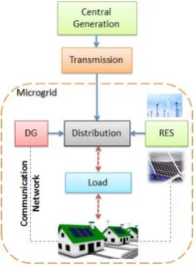
Common Microgrid design is considered as shown in Figure 1, where RES stands for renewable energy sources. However, it is more possible in the future to have microgrids isolated from centralized systems. Hence, the sys-tem used in this research is an isolated power distribution syssys-tem as explained in the next section. In addition, communication network is assumed to exchange data between several elements of the proposed system and the control signals as well.
2.1. Grid Structure
[image:2.595.229.369.504.694.2]The target system of this study is a radial medium tension power distribution system (6.6 kV). It contains several electrical elements including all bus bars and nodes. Electrical machinery and renewable energy sources such as PV units are deployed at a certain location of the system. Also, constant and variable loads are available include-
ing batteries as a storage device. Determined output has been considered for PV source to match with the envi-ronmental situation and different locations. Figure 2 shows the single line diagram of the described system. The mathematical expressions of using the components in the distribution system are expressed by the concept of connecting any device to the distribution network by current injection.
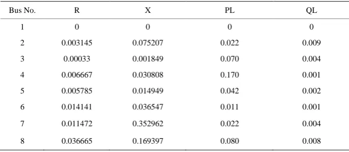
System Parameters are shown in Table 1.
Storage System is simply represented in the form of charging and discharging units as function of voltage and current injected to the system. Energy stored is the integration of power delivered from the system for the time of simulation.
2.2. Control Strategy
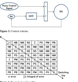
The control strategy is basically implemented to approach two objectives. One is to keep the storage system within the permissible limits and to reduce the generation of the diesel unit to minimum as the other. Diesel unit will receive the signal via communication network which carries out all the required data from the fuzzy logic control scheme prepared in one of the available computers in the network. Once the diesel unit receives the sig-nal from the fuzzy controller the additiosig-nal sigsig-nal will help in the governor action to support the batteries which will operate in their optimal operation due to the fuzzy controller algorithm as shown in Figure 3. Making the diesel work in the same loop with the storage system result in reducing the dependency on the diesel as a fossil fuel and allows the system to work more stable when the storage system absorbs the fluctuations caused by the PV generators.
[image:3.595.130.472.415.533.2]Fuzzy logic control scheme with polar information is proposed for frequency control of the diesel unit. Simi-lar fuzzy logic rules are already used in power system stabilizer (PSS) application [10]. Fuzzy logic controller has three important stages as rule base, fuzzification and defuzzification. As shown in the table of Figure 4, seven fuzzy levels are used for high accuracy, such as NB (negative big), NM (negative medium), NS (negative small), Z (zero), PS (positive small), PM (positive medium) and PB (positive big). In this table, the Z (zero) di-agonal represents the switching line which divides the tables into two parts of control actions; negative signals for deceleration control and positive signals for acceleration control actions.
Figure 2. Single line diagram of the isolated power grid.
Table 1.Power distribution system parameters (pu values).
Bus No. R X PL QL
1 0 0 0 0
2 0.003145 0.075207 0.022 0.009
3 0.00033 0.001849 0.070 0.004
4 0.006667 0.030808 0.170 0.001
5 0.005785 0.014949 0.042 0.002
6 0.014141 0.036547 0.011 0.001
7 0.011472 0.352962 0.022 0.004
[image:3.595.127.467.575.723.2]Figure 3. Control scheme.
Figure 4.Fuzzy logic rules table.
The fuzzy rules assignment table which represents the rule base, then transformed into the phase plane as shown in Figure 5. The sectors A in the first quadrant and B in the third quadrant are defined as the maximum control actions for deceleration and acceleration, respectively. Meanwhile, the control actions in sectors which are located in the second and fourth quadrant can be stated either as deceleration or acceleration. The coordinate of the point p(k) in this figure is given by Equation (1).
( )
( )
,( )
p k = Zp k AsZs k (1) where Zp(k) and Zs(k) are the state of integral of error and error respectively, As is the scaling factor of the error. Normally, the input signals of fuzzy logic controller could be the error, derivative of error and integral of error. However, in this proposed method, measured speed deviation (dw) of the diesel generator and the target dw are selected to be the input signals for two-dimensional fuzzy logic controller. Also the measured energy stored in the batteries Eb and the target stored energy are the inputs of another fuzzy logic control loop.
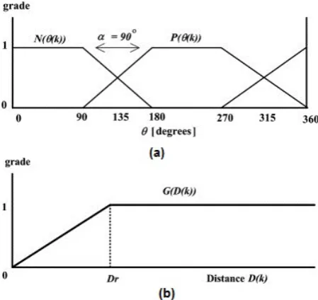
The control actions in the phase plane are transformed into two membership functions during the fuzzification stage. In this stage, the linguistic variables are obtained from numerical inputs based on membership function. In this case, there are two membership functions; angle and radius. The linguistic variables in the angle and radius membership function are the deceleration N(θ(k)) and acceleration P(θ(k)) control actions where their grades are shown in Figure 6.
The angle θ(k) and the radius D(k) can be calculated by using state variables Zp(k)and p(k) in Figure 5 as follows:
( )
1( )
( )
tan A Zs s k k
Zp k
θ = − (2)
( )
( )
2(
( )
)
2 s sD k = Zp k + A Z k (3)
Meanwhile, the grade of the radius membership function, denoted by G(D(k))is specified as:
( )
(
)
( )
( )
( )
for 1.0 for r r r D kD k D
D G D k
D k D
Figure 5. Phase plane of fuzzy logic control with polar information.
Figure 6. (a) Phase plane of fuzzy logic control with polar in-formation; (b) Radius membership function.
where Dr is the radius member. The selected tuning parameters of As and Dr were specified to 10 for both of the values. In the defuzzification stage, the linguistic variables are converted back into numerical variables as the fuzzy controller output based on the membership functions. The fuzzy control rules always bring the current state to the equilibrium point (O) to produce the desired control signal. The control (stabilizing) signal U(k) is determined by the weighted averaging defuzzification algorithm as formulated in (5).
( )
(
(
( )
( )
)
)
(
(
( )
( )
)
)
(
( )
)
maxN k P k
U k G D k U
N k P k
θ θ
θ θ
−
= ⋅ ⋅
+ (5)
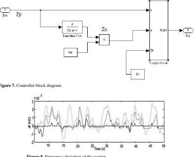
The established control signal will keep the DG unit regulated in such a way to keep the batteries working in their optimum and within the limit. The block diagram of the controller design is shown in Figure 7.
3. Results and Discussion
[image:5.595.185.410.286.498.2]storage system which is supposed to be kept in a certain limit avoiding operation limitations and providing op-timum operation for the system. In fact both of the results are related to each other following the fact of coordi-nation scheme between the diesel unit and the storage system and with the help of the fuzzy controller.
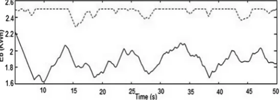
Figure 8 shows the frequency deviation of the system in three cases: First case when there is no any control action to the diesel generator (continuous light-colored line). Second case when conventional controller which is PID is controlling the system as explained in the control strategy (Dashed line) and the third case is when ap-plying the proposed fuzzy logic controller (Continuous dark line). The improvement in the control strategy is clear when frequency deviation is suppressed to its minimum value in the third case. Furthermore, the fluctua-tion in the real power of the system (P) caused by the fluctuated PV generation as shown in Figure 9 is com-pletely distorting the power quality (minus values represent constant load changes). However the presence of batteries as a storage system solved this matter in the form of frequency control because the real power deviation is affecting the frequency as a fact. Power generated from the storage system (Pb) is shown in the same Figure 9
where the minus values representing the discharging state of the batteries.
In addition, The Energy state of the batteries (Eb) kept in the required range using fuzzy logic controller in-suring the optimum operation of the storage system and minimum operation of the diesel generator.
The result of (Eb) status compared with conventional controller as shown in Figure 10, where dashed line is the energy status of the batteries when using conventional controller. It is clear that fuzzy logic has the superior-ity in keeping optimum operation.
4. Conclusion
This research investigates the application of fuzzy logic controller in microgrid implementation. More practical solutions are required in order to overcome the issues related to microgids design especially in the presence of renewable energy. In future the utilization of storage devices will be more applicable, therefore this study con-sidered a storage system during the simulation. Results show the viability of applying fuzzy logic controller to
Figure 7. Controller block diagram.
Figure 9. Real power fluctuations of the system and batrries power.
Figure 10. Energy stored trajectory of the storage system (Dashed line: Using PID controller. Continuous Line: Using fuzzy controller).
balance the generation and demand keeping stable frequency with the best usage of the storage system. Future work aims to find more intelligent applications in mocrogrids considering wind turbines and other renewable sources and storage systems such as fuel cells.
References
[1] González, J.S., Payán, M.B., Santos, J.M.R. and González-Longatt, F. (2014) A Review and Recent Developments in the Optimal Wind-Turbine Micro-Siting Problem. Renewable and Sustainable Energy Reviews, 30, 133-144.
http://dx.doi.org/10.1016/j.rser.2013.09.027
[2] Bernard, M.Z., Mohamed, T.H., Ali, R.,Mitani, Y. and Qudaih, Y.S. (2013) PI-MPC Frequency Control of Power System in the Presence of DFIG Wind Turbines. Engineering, 5, 43-50.
[3] Caia, D.W.H., Adlakhab, S., Lowc, S.H., De Martinid, P. and Mani Chandyc, K. (2013) Impact of Residential PV Adoption on Retail Electricity Rates. 62, 830-843.
[4] Qudaih, Y.S., Elbaset, A.A. and Hiyama, T. (2010) Simulation Studies on ECS Application in a Clean Power Distribu- tion System. International Journal of Electrical Power and Energy Systems, 33, 43-54.
http://dx.doi.org/10.1016/j.ijepes.2010.08.005
[5] Zhang, L.F., Gari, N. and Hmurcik, L.V. (2014) Energy Management in a Microgrid with Distributed Energy Re- sources. 78, 297-305.
[6] Saxena, D., Singh, S.N. and Verma, K.S. (2010) Application of Computational Intelligence in Emerging Power Sys- tems. International Journal of Engineering, Science and Technology, 2, 1-7.
[7] Qudaih, Y.S. and Mitani, Y. (2011) Power Distribution System Planning for Smart Grid Applications Using ANN.
Energy Procedia, 12, 3-9. http://dx.doi.org/10.1016/j.egypro.2011.10.003
[8] Kaehler, S.D. (2013) http://www.seattlerobotics.org/encoder/mar98/fuz/fl_part1.html
[9] Halmann, M.M. and Steinberg, M. (1999) Green House Gas Carbon Dioxide Mitigation. CRC Press.
[image:7.595.163.437.283.381.2]