Path Determination using Improved BFS approach in
Wireless Sensor Network
Neha Thapar
M.tech, Department of Software Engineering Institute of Technology & Management University
Gurgaon, India
Shilpa Mahajan
Department of Computer ScienceITM University Gurgaon, India
ABSTRACT
Wireless Sensor Network (WSN) is type of network which consists of a collection of tiny devices called sensor nodes. The effective communication type in sensor network is aggregative communication. In such a path is constructed between all the participant nodes and generate an aggregative path. Each node includes its data to this aggregative path and perform the communication to the sink node. In this work, we will be proposing an energy efficient method based on graph theory that can be used to find out minimum path based on some defined conditions from a source node to the destination node.
Initially, a sensor area is divided into number of levels by a base station based on signal strength. The base station is placed at the corner with specific range. The nodes in the range of base station can perform direct communication with base station. The presented work, will generate and effective route under the energy, sensing range and fault criticality parameters. It is important to memo that this method will always locate minimum path and alternate path in case of node crash . To identify the effective route, a BFS based approach is suggested in this work. The work will improve the network life, reduce the energy consumption and improve the network communication.
Keywords
Wireless sensor network, BFS approach, , Energy Efficient, shortest path.
1.
INTRODUCTION
WSN is a collection of thousands of low cost smart sensor nodes. Sensor nodes are deployed in a remote monitoring area. Sensor nodes sense data from monitoring area and broadcast to base station. In WSN's sensors are distinguished by their limited energy, processing, memory resources and unreliable wireless link as well as high degree of mobility. However, sensor nodes have small memory, slow dispensation speed, and scant energy supply. These limitations are typical uniqueness of sensor nodes which effects, sensor networks life and the quality . When power proficient communication is considered, it is important to capitalize the nodes lifetimes, reduce bandwidth requirements by using local teamwork among the nodes, and tolerate node failures, besides delivering the data efficiently. As the data is transferred over the network each sensor spend some energy in receiving data, sending data and forwarding data. Because of this network life depends on how much energy spend in each transmission. Due to the energy constraints, wireless sensors usually have a limited transmission range, making multi hop data routing towards the PN (processing node) more energy efficient than direct transmission (one hop). A primary design goal for
wireless sensor networks is to use the energy efficiently. To accumulate the energy of nodes in wireless sensor network a GDD(Grid-based Directed Diffusion) model is being projected [1]. Each node uses its location to associate itself with a implicit grid, where every other node in a scrupulous grid square forward the message to neighbor nodes. Only single node participates in inter-grid interests and rest correspond with the node. The sensed data is being limited in clusters, which save energy and decrease delay. To increase the network life span [2] a distributed multipath fault tolerant routing scheme has been developed. This is divided into two parts: effective size cluster formation and multipath data routing tree formation for fault tolerance. The level based multipath tree mechanism is developed to tolerate nodes and transmission fault. And the effective size cluster information is employed to prevent traffic over head and energy hole.
To design a network in a way to efficiently utilize the energy of nodes to lengthen the lifetime of the network an efficient routing technique is required. As communication put away significant amount of battery power, sensor nodes should spend as little energy as possible when in receipt of and transmitting of data [3-5].
The proposed is based on single bound level by level data transmission from the base station to the ordained node by forming a series. The trail will be preferred using BFS approach of graph theory.
2.
BACKGROUND
The unique and simple approach was direct transmission in which each sensor node will sense & transmit its data to BS individually. Since base station is located far away from sensor nodes resulting higher transmission cost. Because of this high cost transmission the energy of nodes drain off faster and thus having short system life-time. In order to solve the problem, clustering based protocols were proposed where a cluster is a group of sensor nodes, with a head node managing all other member nodes. The head nodes are responsible for coordinating member nodes, congregation data within the clusters, aggregating data and forwarding the aggregated data to the base station.
the network such that the nodes die arbitrarily and in essence at the same rate. However, the drawback of LEACH is that the dynamic cluster formation causes a massive overhead that increases the network energy indulgence.
Multipath description of Directed Diffusion paradigm[7] uses multiple routing paths to transfer data, so that node failures in one path can be overcome by sending the data through multiple paths, which increases energy consumption. Energy constraint is very critical to reliability in WSN. Nodes stop working id they deplete their energy, thus links will break and some parts of or even the whole of the network will be failed. To minimize the energy consumption[8] and to increase the network reliability, an Energy- aware, Load- balancing and Fault- Tolerant routing scheme is being proposed. In this a route discovery phase is being designed to make the sensors construct a hop leveled network which is mesh structure. To measure the failed nodes a cross layer design is adopted to compute the transmission delay. And when nodes fail, the new path will be generated. To improve the reliability of data routing in wireless sensor network a Reliable Fault Tolerant Multipath(RFTM)[9] routing protocol is being introduced in this paper. It takes into account both reliability demand and link quality to determine the number of desired multiple disjoint paths between the sink and source nodes.
PEGASIS(Power efficient gathering in sensor information system)[10] a near optimal chain based protocol. In this each node communicates with the close neighbor and takes turn transmitting to the base station, thus reducing the amount of energy spent per round. The main idea in PEGASIS is for each node to receive from and transmit to close neighbours and take turns being the leader for transmission to the BS. This approach will distribute the energy load evenly among the sensor nodes in the network. The nodes will be organized to form a chain, which can either by accomplished by the sensor nodes themselves using a greedy algorithm starting from some node. Alternatively, the BS can compute this chain and broadcast it to all the sensor nodes.
In contrast with PEGASIS , an efficient routing protocol [11] Chain- Chain based routing protocol (CCBRP) is being proposed .It achieves bare minimum energy consumption and bare minimum delay. It divides the WSN into a number of chains(Greedy algorithm is used as in PEGASIS) and run into two phases. In the first phase, sensor nodes in each chain broadcast data to their chain organizer nodes in corresponding. In the second phase, all chain leader nodes form a chain (also, using Greedy algorithm) and choose randomly a leader node then all chain leader nodes send their data to this chosen leader node. This chosen leader node fuses the data and forwards it to the Base Station, BS.
COSEN(A Chain Oriented Sensor Network for Efficient Data Collection) [12] in contrast to PEGASIS is a two-tier hierarchical chain-based routing scheme. COSEN is efficient in the ways that it ensures maximal utilization of network energy, it makes the lifetime of the network longer. Chain-Based Hierarchical Routing Protocol, named as CHIRON [13], is to split the sensing field into a number of smaller areas, so that it can create numerous shorter chains to reduce the data transmission delay and surplus path, and effectively conserve the node energy and prolong the network lifetime. EECB (Energy-Efficient Chain-Based routing protocol )[14] that is an improvement over PEGASIS. EECB uses distances between nodes and the BS and residual energy levels of nodes to decide which node will be the leader that takes charge of transmitting data to the BS. Also, EECB adopts distance threshold to avoid configuration of LL (Long Link) on the
chain.
3.
MOTIVATION
The main idea in BFS approach[15] is that it begins at the root node and explores all the adjacent nodes. Then for each of those neighbor nodes in turn, it inspects their neighbor nodes which were unvisited, and so on. It has been proved by initiation that breadth first search is the shortest path tree from its root. The shortest path is being found out using distance parameter.
Fig1. BFS tree approach
In Improved BFS approach as the data is transferred over the network each sensor spend some energy in receiving data, sending data and forwarding data. Because of this network life depends on how much energy spend in each transmission. Due to the energy constraints, wireless sensors usually have a limited transmission range, making multi hop data routing towards the PN (processing node) more energy efficient than direct transmission (one hop). A primary design goal for wireless sensor networks is to use the energy resourcefully.
4.
PROPOSED WORK
The presented work has defined an effective route construction under the energy and fault criticality analysis. This will accomplish the energy balancing over the network while performing the communication and the fault criticality analysis will generate a deterrent communication path.
4.1
Assumptions
a. All nodes have same and sufficient amount of preliminary energy.
b. A node can trust each other and there is no malevolent intruder.
c. Each node or sink has ability to broadcast communication to any other node and sink directly.
d. Each sensor node has position information.
e. Every sensor nodes are preset after they were deployed.
f. WSNs would not be maintained by humans.
g. Wireless sensor nodes are deployed compactly and arbitrarily in sensor field.
4.2
Basic Idea
will keep the energy balancing over the network while performing the route assortment.
4.3
Main Phases
1. Level Assignment
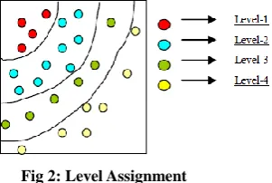
[image:3.595.109.260.204.305.2]First, the sensor network say M*M will be alienated into number of concentric circles defined as levels. Based on signal potency from the base station each node in the network is assigned its own level. These levels depend on various parameters such as distance, energy, location of the base station is shown in Fig2.
Fig 2: Level Assignment
2. Route Discovery Phase
This phase is based on query and reply cycles and all the information is stored in all intermediary nodes along the route. The route request packet will be sent by each node to find its neighboring nodes those are one bound away from it. The source node will maintain the routing table as shown in fig 3.
Each node broadcasts a so called HELLO message to know its neighborhood nodes ,so that it can directly communicate with. The message will be broadcasted with TTL=1 and as the message is broadcasted a node will wait for the route reply message. After receiving the route reply message from the nodes, it will update the routing table entry destination ID. The new routes entry will be accounted in sequence number. The energy levels of the node will be saved in battery status. The inter distance between such nodes will be represented by the distance pillar. The visit field will trace the route from source to destination point. The neighbor nodes will be identified by TTL=1 which are one hop away. The fault over the communication path depends on the distance and energy loss. As the energy loss occur over the path, some data will be lost.
Fig 3: Routing Table
3. Improved Breadth First Search
In graph theory, improved breadth -first search(IBFS) is a graph search algorithm[16] that begins at root node at explores all the adjacent nodes. Then it explores all the nearest nodes that are uncharted nodes , until it finds the goal. This has been proved that BFS is a shortest path tree from its root. As some communication is performed over the network, some amount of energy is lost by the network with each communication over the network. To achieve the effective communication over the network, energy optimization is required with each network operation. One of such critical network operation is route identification. An effective route is generally considered as the shortest path between the source and the destination. But if the data is continuously send over this route, the energy loss over the route nodes will be fast and the energy unbalancing over the network will occur. The presented work, will generate and effective route under the
energy, sensing range and fault criticality parameters. As the energy level of node will be lesser than defined threshold, a new route will be considered as the effective route. The work will keep the energy balancing over the network while performing the route selection. The fault over the communication path depends on the distance and energy loss. As the energy loss occur over the path, some data will be lost. The formula taken for estimation of fault over the communication path is given as under:
Fault=Distance(I,j)*Min(Energy(i),Energy(j))+Distance(I,j)*P acketDropProbRatio
Here I and j are source and estimation nodes.
Distance is the distance between two nodes.
Energy is the current energy of given node.
PacketDropProbRatio is the Packet Drop Ratio Actually Considered for loss.
The flow of presented work is given here under:
Fig 4: General flow of algorithm
5.
PROPOSED AGLORITHM
(i) Define a sensor network with N number of nodes called (S1,S2…Sn)
(ii) Define each node with energy specification, Range, failure probability.
(iii) Accept the communication time stamp for each node
(iv) For (I =1 to n) /* Process all nodes*/ {
(v) For (j=1 to n)
/* Process all adjacent to node(i)*/ {
Dist=CalcDist(Node(i),Node(j)) (vi) If (Dist > Range )
Set DistMat(Node(i),Node(j))=0
/* Only an adjacent in range can be the communication neighbor*/
(vii) If (Energy (Node(j)) <Threshold ) Source
ID
Destination ID
Node Status
Sequence No's
Energy
Distan-ce
Visit TTL Fault
Establish the network with n nodes and defined parameters
Implementation of Improved DFS Based Protocol under different parameters
Analysis in terms of Network lifetime and Throughput
Result Analysis under different scenario and route settings
Set DistMat(Node(i),Node(j))=0
/* Only a high energy node can be the communication neighbor*/
(viii)If (FailureProb(Node(j)) > FaultThreshold) Set DistMat(Node(i),Node(j))=0
/* Only a node with lesser fault ratio can be the communication neighbor*/
} }
(ix) Set Source Node SrcNode and Destination Node DstNode for the communication
(x) For t=1 to MAX_ITERATIONS {
(xi) For i=1 to MAX_PACKETS {
(xii)If(Node(i).TimeStamp=t)/*If communication is performed on current time stamp, the node wil be active*/
(xiii){
(xiv)Set Node(i).Status=Active (xv) Call BFS (distMat)
/*Generate Path on Fault Effective Matrix*/ (xvi) Perform Communication over Path generated
from BFS (xvii) } (xviii) }
(xix) Perform Network Analysis under different Parameters
(xx) }
BFS(distMat)
/*distMat is the actual distance matrix between connected nodes under the distance and energy vector */
{
Step 1: Path=[]
[Set initially path at black array]
Step 2: for ( i = 1 to N)
/* Process All Nodes
{
Step 3: Set status(i) = NV /*Initialize the Nodes*/
Set parent(i) = Null
}
Step 4: For ( i = 1 to n)
{
Step 5: if (Node(i).Status=Active)
{
Step 5: if (status(i) = UV)
/* If the node is a node visiting node Process the Node*/
{
Step 6: TravelNode(Node(i) )
}
}
Return path;
}
TravelNode (node1,distMat)
/* node1 is the current node to process for BFS based node visit*/
{
Step 1: if(Node(i).Status=Active)/*If communication is performed on same time stamp*/
{
Set status(node1) = V;
Path=Path U { V }
}
/* node is visited*/
Step 2 : for i=1 to N
/* Process all nodes*/
{
Step 3: if (distMat(node1,i)<>0)
/* identify the adjacent of current Nodes*/
{
Step 4: if (status(Node(i)) == NV )
/* If adjacent node is not visited*/
{
Step 5: Parent(Node(i)) = node1
TravelNode(Node(i) )
/*Repeat process on all adjacent*/
}
}
}
}
6.
SIMULATION
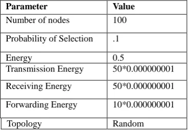
[image:4.595.328.513.624.752.2]A network requires simulation parameters to be set so that the network can bring to work. The simulation parameters include: number of sensor nodes, a base station and the energies for transmitting, receiving, forwarding and probability of selection of nodes. The various simulation parameters which are considered for network establishment are given below:
Table 1: Simulation Parameters
Parameter Value
Number of nodes 100
Probability of Selection .1
Energy 0.5
Transmission Energy 50*0.000000001
Receiving Energy 50*0.000000001
Forwarding Energy 10*0.000000001
A Wireless sensor network is simulated in the MATLAB tool. A stationary network with a fixed number of sensors randomly deployed is simulated. The range of each sensor is considered fixed and so is the initial energy of the sensor which is kept equal for all sensors without any loss of generality. A 100×100m area is considered for deploying the sensors randomly.
7.
EXPERIMENTAL RESULTS
The complete output of the proposed algorithm is shown in figure 5.
Fig 5: Communication path of proposed algorithm
Figure 5, is showing the communication scenario with effective route generation. The network is here established with 100 nodes. The base station is placed at distant location. The communication route is established between the source node and the base station. As shown in the figure, the network is divided in levels based on the sensing range. While performing the hop selection, one node is taken from each level. The red nodes define the dead nodes.
Fig 6: Communication path at round 22
Figure 6 shows that communication path changes as the node gets faulty and it changes its route path at round 22 and again selects the shortest path using BFS approach.
Fig 7: Communication path of existing algorithm
Figure 7 is showing the path for existing algorithm that is simple Breadth First Search in which nodes are deployed randomly with the base station at the corner and the undeviating path is generated. The proposed approach is better than existing approach as it includes the distance , energy and fault parameters.
Fig 8: Energy analysis
Figure8, is showing the performance of proposed and existing algorithm of energy analysis respective to the rounds. Here x axis represents the rounds and y axis represents the energy retain the network. As shown in the figure, initially the maximum energy is present over the network. With each communication round some amount of energy consumed by each participating node. Here aggregative energy consumption over the network is shown.
Fig 9: Distance analysis
Figure 9 is showing the performance of proposed and existing algorithm of the distance analysis respective to the number of rounds. As shown in the figure as the rounds increases in the obtainable graph, the average communication distance is also increased. The distance is increasing because the intermediate nodes loose the energy and new path is generated over the network that can consume more energy.
Figure 10 is showing performance of proposed and existing algorithm of the hop count analysis respective to the number of rounds. As shown in the obtainable graph as the rounds increases, the average hop count is also increased. The distance is increasing because the intermediate nodes loose the energy and new path is generated over the network that can consume more energy.
Fig 11: Dead node analysis
[image:6.595.54.288.445.596.2]Figure 11, is showing the performance of proposed and existing algorithm of dead node analysis respective to the rounds. Here x axis represents the rounds and y axis represents the dead nodes. Here the number of sensor nodes varies from 2 to 22 and sensing range of each node is 40. As shown in the figure, initially no node is dead but as the communication is performed some amount of energy consumed by participating nodes. After some rounds nodes start losing the energy and nodes get dead. This shows the presented work is better as the intensity of dead nodes gets better
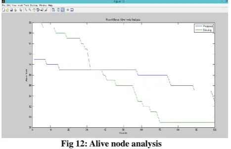
Fig 12: Alive node analysis
Figure 12, is showing the performance of proposed and existing algorithm alive node analysis respective to the rounds. Here x axis represents the rounds and y axis represents the alive nodes. As shown in the figure, initially all nodes are alive but as the communication is performed some amount of energy consumed by participating nodes.
8.
CONCLUSION
In this paper, we have considered the routing approaches in sensor networks from the security viewpoint. The work is analyzed the threats against ad hoc routing and presented the requirements that need to be addressed for secure routing. Existing secure routing algorithm for sensor network is not that much effective because these networks are only based on energy and distance constraint. But in this work, the error rate consideration is taken under the distance analysis. It means
there are higher chances of data drop for high distance communication. In this present work, an adaptive BFS based approach is suggested for the detection of effective path over the network. The route generation is here performed under the distance, energy and the error rate analysis. The presented approach is effective in terms of energy and the time as well as provides a reliable route over the network. The obtained results shows that the presented approach has improve the network reliability and the energy.
9.
ACKNOWLEDGEMENT
This research paper is made possible through the help and support from everyone, including: parents, teachers, family, friends, and in essence, all sentient beings. Especially, please allow me to dedicate my acknowledgment of gratitude toward the following significant advisors and contributors:
First and foremost, I would like to thank Mrs. Shilpa Mahajan for her most support and encouragement. She kindly read my paper and offered invaluable detailed advices on grammar, organization, and the theme of the paper.
Finally, I sincerely thank to my parents, family, and friends, who provide the advice and financial support. The product of this research paper would not be possible without all of them
10.
REFERNCES
[1] Yun li,Shuangquan Xiong,Qianbin Chen and Fei Fang: “Grid based directed diffusion in wireless sensor network" ,IEEE,Communication and Networking, pages 814-818,2007.
[2] Prasenjit Chanak, Indrajit Banerjee,"Distributed multipath fault tolerance routing scheme for wireless sensor network", IEEE, Third International Conference on Advanced Computing and Computing Technologies, pages 241-247, 2013.
[3] W. Mangione-Smith and P.S. Ghang, “A Low Power Medium Access Control Protocol for Portable Multi-Media Systems,” In Proceedings 3rd In- terna-tional Workshop on Mobile Multimedia Com- munica-tions, Princeton, September 1996, pp. 25-27.
[4] K. M. Sivalingam, M. B. Srivastava and P. Agrawal, “Low Power Link and Access Protocols for Wireless Multimedia Networks,” In Proceedings IEEE Vehicular Technology Conference, Phoenix, 4-7 May 1997, pp. 1331-1335.
[5] M. Stemm, P. Gauthier, D. Harada and R. Katz, “Reducing Power Consumption of Network Interfaces in Hand-Held Devices,” In Proceedings 3rd International Workshop on Mobile Multimedia Communications, Prin- ceton, September 1996, pp. 25-27.
[6] W. R. Heinzelman, A. Chandrakasan and H. Bala- krishnan, “Energyefficient Communication Protocol for Wireless Microsensor Networks,” In 33rd Annual Hawaii Interna-tional Conference on System Sciences, Hawaii, 4-7 Janu-ary 2000, pp. 3005-3014 .
[7] Chalermek Instanagonwiwat, Ramesh Govindan, Deborah Estrin, "Directed Diffusion: A Scalable and Robust Communication Paradigm for Sensor Networks", in Proceedings of ACM MobiCom 2000, August 2000, Boston, Massachusetts.
sensor networks",IEEE, Communications and Networking in China, pages 1-5,2006.
[9] Hind Alwan , Anjali Agarwal," Reliable fault tolerant multipath routing protocol for wireless sensor network",IEEE, Communications (QBSC), 25th Biennial Symposium, pages 323-326,2010.
[10]Stephanie Lindsey and Cauligi S.Raghavendra :"Power efficient gathering in sensor information system",IEEE,2001.
[11]Samia A. Ali and Shreen K. Refaay,"Chain- Chain based routing protocol", IJCSI International Journal of Computer Science Issues, Vol. 8, Issue 3, No. 2, May 2011.
[12]N. Tabassum, Q. E. K. M. Mamun and Q. Urano COSEN: A Chain Oriented Sensor Network for Efficient Data Collection,” Proceedings of the Global Tlecommu-nications Conference, San Francisco, 1-5 December 2003, pp. 3525-3530.
[13]K. Majumder, “Clustered Chain Based Power Aware Routing Scheme for Wireless Sensor Networks,” Interna-tional Journal on Computer Science and Engineering, Vol. 2, No. 9, 2010, pp. 2953- 2963 .
[14]Yongchang Yu ," An Energy-Efficient Chain-Based routing protocol in Wireless Sensor Network", IEEE,
Computer Application and System Modeling (ICCASM), 2010 International Conference, pages V11-486-V11-489,2010.
[15]Shilpa Mahajan, Jyoteesh Malhotra,"Energy efficient path determination in wireless sensor network using BFS approach",Wireless Sensor Network, 3, pages351-356,2011.