Maximizing CFO Estimation Range using a New OFDM
Symbol Structure
Shaimaa ElSayed Ibrahim
Lecturer Assistant, Dept. of EECT, Modern Academy in Ma'adi,
Egypt
K.A. ElBarbary
Professor and Head of Electric Engineering Department, Suez Canal
University, Egypt
Ragab M. El-Sagheer
Lecturer, Dept. of Electrical Communication, Al-Azhar University in Cairo, Egypt
ABSTRACT
Carrier frequency offset (CFO) is a major contributor to the inter-carrier interference in orthogonal frequency division multiplexing (OFDM) systems. In order to overcome CFO at the receiver, a new OFDM symbol structure based on extending the transmitted symbol by inserting extra bits at the front of it before transmission is applied in this paper. The proposed method is capable of correcting frequency offset in the range of multiples of subcarrier spacing depending on the number of added extra bits. This is performed at the expense of transmitted power and data rate due to the insertion of extra bits. Simulation results indicate the performance improvement over both additive white Gaussian noise (AWGN) and multipath fading channels.
Keywords
Orthogonal frequency division multiplexing (OFDM), convolution, cyclic prefix (CP), equalizer, multipath channel
1.
INTRODUCTION
Due to its immunity to multipath fading and high spectral efficiency, orthogonal frequency division multiplexing (OFDM) has been adopted as a modulation format in a wide variety of wireless systems such as digital video broadcasting-terrestrial (DVB-T), wireless local area network (WLAN), and worldwide interoperability for microwave access (WiMAX) [1]. The sensitivity of OFDM systems to frequency offset compared with single carrier systems is a major disadvantage. In general, Frequency offset is defined as the difference between the nominal frequency and actual output frequency. In OFDM, the uncertainty in carrier frequency, which is due to a difference in the frequencies of the local oscillators in the transmitter and receiver, gives rise to a shift in the frequency domain. This shift is also referred to as frequency offset. It can also be caused due to the Doppler shift in the channel. The demodulation of a signal with an offset in the carrier frequency can cause large bit error rate and may degrade the performance of a symbol synchronizer due to its effect of inducing inter-carrier interference (ICI) which in turn destroys orthogonality between subcarriers.
It is therefore required to minimize/eliminate the effect of this frequency drift and this was the motivation behind researches in that field. Researches were classified into two categories. First, non-data aided category in which blind estimation of CFO value is determined [2] then compensating its effect at receiver side. Second category is the data aided category in which the system bandwidth was reduced as a result of transmitting repetitive sequence through channel. Either using any of two mentioned categories makes a tradeoff between
system bandwidth, transmitted bit rate and increasing receiver complexity.
A simple data aided scheme that estimates low CFO values without increasing receiver complexity is explained in [3], where the Self Cancellation (SC) method has been applied with the main idea of modulating one data symbol onto a group of subcarriers with predefined weighting coefficients where a group, in the general case, consists of subcarriers. By doing so, the ICI signals generated within a group can be “self-cancelled” each other. But a reduction in system bandwidth efficiency has been occurred by a factor of as a result of the redundant modulation.
Keeping an efficient bandwidth as in normal OFDM system was the goal of [4] and [5] which developed an ameliorated ICI cancellation scheme based on the analysis of self ICI cancellation but at the expense of increasing receiver complexity as a result of doubling the FFT length. Another method for eliminating the ICI effect in OFDM system without reducing system bandwidth was applied in [6] by equalizing the complex weighting coefficients of interference but also at the expense of increasing receiver complexity.
Decreasing the effect of CFO without sever decreasing in transmitted bandwidth or increasing in receiver complexity was the goal of [7] where the use of frequency-domain correlative coding with correlation polynomial in OFDM mobile communication systems was used. ICI canceling codes with rate of for OFDM systems are proposed in [8] in order to get higher capacity lower bounds and lower bit error rates (BERs) by generalizing the rate codes in [3] with the advantage of needing a minor increase in the implementation complexity.
Another strategy is to first estimate CFO then eliminates its effect at receiver. Methods in [9] and [10] which depends on data contained in CP part to estimate CFO values follow that strategy but suffered from low CFO estimation range till where is defined as a ratio of the CFO to the subcarrier spacing. Estimator in [11], depending on the FFT length (N), can provide very high accuracy over a wide acquisition range with while keeping a very low computational complexity. Estimation range in [10] which uses a comb-type signal in frequency domain can also be extended but at the expense of severe lowering the transmitted bandwidth.
This paper is organized as follows: an overview of carrier frequency offset in OFDM system is provided in Section 2. Section 3 discusses the description of CP-based technique in AWGN and multipath channels. In Section 4, we introduce the proposed scheme in both AWGN channel and multipath Rayleigh channel. A modification in transmitting OFDM symbol structure for offset estimation with lower equalization process is also discussed in multipath channels. Section 5 demonstrates the convolution process with its two types, linear and circular convolution, showing the steps for obtaining simple equalization process. Simulation results which show a noticeable performance improvement in terms of BER at the presence of high CFO values and some further discussions in the performance of proposed scheme are provided in Section 6. Finally, conclusions are provided in Section 7.
2.
CARRIER FREQUENCY OFFSET IN
OFDM
A carrier offset at receiver due to a difference in the local oscillators in the transmitter and receiver or Doppler shift can cause loss of subcarrier orthogonality, and thus can introduce ICI and severely degrade the system performance [12]. The uncertainty in carrier frequency gives rise to a shift in the frequency domain where all the subcarriers experience the same frequency offset . Such behavior is modeled as a complex multiplicative distortion in the time domain, of the received data [10], assuming that the sampling period is the inverse of sampling frequency, is the number of subcarriers and the subcarrier spacing is the inverse of .
The received signal with the effect of , without AWGN is:
(1)
As is the OFDM symbol time divided by , (1) can be expressed as:
(2)
Let the difference between the transmitter and receiver carrier frequencies is denoted by and the normalized CFO, given as . Equation (2) can be written as:
(3)
This can be expressed as:
(4)
Where the transmitted signal is the N-pins IFFT of the data signal expressed as:
(5)
Where the N complex-valued are symbols that belong to a QAM or PSK constellation and modulate N orthogonal subcarriers.
3.
CP-BASED TECHNIQUE
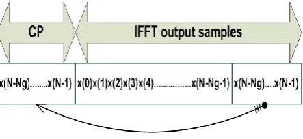
At the transmitter of cyclic prefix-based technique [13], before transmission, the sequence of the IFFT output samples of each OFDM symbol is typically extended from to by prefixing at the start the last samples of the N-point IFFT result, yielding the cyclic prefixed signal:
(6)
[image:2.595.320.542.148.250.2]Fig.1 shows the transmitted OFDM symbol structure in case of using CP based scheme. Therefore, CP is a kind of redundant information [2] used to protect transmitted symbols from ISI resulting from multipath channels.
Fig. 1:OFDM symbol structure used in cyclic prefix based technique.
When a training symbol with repetition property is transmitted, the receiver can acquire the CFO estimation based on the auto-correlation of the received signal without exact knowledge on the training symbol [14]. The fractional frequency offset is estimated from the phase of the correlation of cyclic prefix samples and their counterpart. Then it is corrected [15] before taking the FFT.
Assuming that is distributed equally over positive and negative sides around zero as in [1], a CFO results in phase rotation of in the received signal, leading to the following received samples:
(7)
The phase difference between CP and the corresponding part of an OFDM symbol (spaced N samples apart) caused by CFO is . The CFO can be estimated from the product of CP and the corresponding part of an OFDM symbol as
(8)
The noise, such as AWGN, has great influence on the performance of this method [2], [16], [17]. In order to reduce the noise effect, its average can be taken over the samples in a CP interval as
(9)
To increase the accuracy of this method, L-OFDM symbols are employed to perform the CFO estimation [2], [16]. Hence, the estimation result is expressed as:
(10)
, l indicates OFDM symbol number. Since the argument operation is performed using , the range of CFO estimation in (10) is – so that and consequently, integer multiple of carrier spacing cannot be estimated by this technique.
. Hence; CP scheme could not be used in
this case.
The range of CFO estimation can be increased by reducing the distance between two blocks of samples for correlation. This is made possible by using training symbols that are repetitive with some shorter period [17].
In multipath channel, the received signal is received from v-paths. To avoid inter-block interference (IBI), the CP should be at least as long as channel order v, and it should be discarded at the receiver side [16]. Another advantage of using CP for the guard symbol is that it helps to maintain the receiver carrier synchronization [19]; the utilization of Cyclic Prefix (CP) enables OFDM system to convert a frequency selective channel into a parallel collection of frequency flat channels, leading to greatly simplified equalizer design [14].
However, Due to the multipath propagation, a part of the guard interval is corrupted by preceding symbols [16], [20]. The estimated CFO needs to be within the uncorrupted guard interval as:
(11)
Where
and where * indicates linear convolution process, is the channel impulse response with length and is the received OFDM symbol with length
4.
PROPOSED TECHNIQUE
DESCRIPTION
In proposed scheme, instead of prefixing the OFDM symbol at the start by the last samples of the N-point IFFT, it is extended by the first samples of the N-point IFFT as shown in Fig. 2 and thus reducing the distance between two blocks of samples for correlation, leading to an extension in estimation range as will be shown in the rest of this section. The new OFDM transmitted symbol structure for proposed scheme will take the form
[image:3.595.318.538.405.739.2]
(12)
Fig. 2:OFDM symbol structure used in proposed technique in AWGN channel.
As in CP-scheme, assume that is distributed equally over positive and negative sides around zero, the phase difference between CP-proposed and the corresponding part of an OFDM symbol (spaced Ng samples apart) caused by CFO is results in extending the estimation range from in CP-technique to – in proposed technique.
The CFO can be estimated from the product of CP-proposed and the corresponding part of the received OFDM symbol as:
(13)
As in CP-scheme, to reduce the noise effect, its average can be taken over the samples in a CP-proposed interval. Also, the accuracy can be increased if L-OFDM symbols are employed as: (14)
4.1
Transmission in Multipath Channel
With cyclic prefix (CP) and IFFT/FFT processing, the frequency selective fading channel can be easily converted into parallel flat fading sub-channels. In flat fading channels, the same degree of fading takes place for all of the frequency components transmitted through a radio channel and within the channel bandwidth [19]. In this way, the linear channel convolution is converted into circular convolution, making the equalization process simpler [21], [22].
In proposed scheme, this cannot be done specifically the extended samples are appended after the IFFT processed information symbols in time domain. So in case of transmission through a multipath channel, another extra samples which are copies of last samples of are located in front of .
Serial Tx bits Mapping (PSK, QPSK,MQAM) S/P X(0) X(1) X(N-1) x(0) x(1) x(N-1) . . . . . . . . IFFT s(0)=x(0) s(N-1)=x(N-1) . . . . Adding
a copy of last Ng samples
followed by a copy of first Ng samples
in front of the symbol s(1)=x(1) s(-2Ng)=x(N-Ng) s(-Ng-1)=x(N-1) . . s(-1)=x(Ng-1) . . s(-Ng)=x(0) P/S Channel (multipath, AWGN, adding offset) S/P r(-2Ng) r(N-1) . . . . . . . . . . . . . . Offset estimation & correction, extracting data subcarriers y(0) y(1) y(N-1) . . . . FFT Y(N-1) Y(0) Y(1) . . . . P/S Serial Rx bitsDemapping
(PSK, QPSK,MQAM) . . . . . Frequency domain equalizer
[image:3.595.55.282.503.640.2]Fig. 3 shows the general block diagram for proposed scheme in case of transmitting through a multipath channel in which the N-point X(k) frequency domain symbols are converted to the N-point x(n) time domain samples through N-points IFFT stage, where n=0,1,2,…,N-1. After that and before transmission, a new proposed OFDM symbol structure is performed as follow
(15)
Although this symbol structure makes the equalization process possible using one-tap equalization, it causes a reduction in power and bandwidth by a factor of due to the extension by extra samples. If N is large enough, this loss can be ignored.
At receiver side, a CFO estimation and correction stage is applied. Then the free CFO-time domain samples enters the FFT stage to convert the time domain samples to its corresponding frequency domain symbols before using frequency domain-single tap equalizer in which the transmitted symbols are estimated by dividing the frequency domain received symbols by the frequency domain channel impulse response. Finally, those estimated symbols enter the de-mapping stage.
4.2
CFO Estimation and Correction in
Multipath Channel
As the received OFDM symbol is the result of linearly convolved of OFDM symbol of length with the channel impulse response of length v, the resultant OFDM symbol will have the length . And the received proposed OFDM symbol with will be
(16)
Where
Because of the CFO estimation needs to be within the uncorrupted guard interval, the CFO can be estimated from the product of CP-proposed and the corresponding part of the received OFDM symbol in case of multipath channel as:
(17)
As the frequency offset is solely estimated with the help of induced extra samples, the number of samples in is important in deciding the performance of the estimator. Various lengths like can be used.
Once value is estimated, the received signal can be corrected by multiplying the received OFDM symbol by the conjugation
of
resulting in .
After correction stage and before FFT stage, a replacement of by should take place. In this way, the linear channel convolution is converted into circular convolution, making the equalization process simpler using one-tap frequency domain equalizer as it was difficult without this replacement. So, this transmitted OFDM symbol structure enables simple equalization process with an increasing in CFO estimation range. The difference
between linear and circular convolution is discussed in next section.
5.
CONVOLUTION PROCESS AND
EQUALIZATION
Convolution is a basic mathematical tool that plays an important role in understanding all communication systems. It can be classified into linear convolution and circular convolution with the concept that, convolution in time-domain is equivalent to multiplication in frequency domain.
This property is important in estimating the transmitted symbols at the receiver side when the channel is multipath channel. Because it simplifies the equalization process to be simple using one-tap frequency domain equalizer through dividing the received samples by the frequency domain channel impulse response. The question here is that, which is preferred to deal with, is it linear convolution or circular convolution?
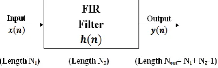
To understand the difference between the linear convolution and circular convolution, consider a Finite Impulse Response (FIR) filter having impulse response with length N2 as
shown in Fig. 4.
Fig. 4:Transmission through Finite Impulse Response linear system.
When an input sequence is applied with length N1 at its
input, an output sequence will be produced with length equals to (Nout = N1+N2-1). As a matter of fact, linear filtering
is same as linear convolution which has a mathematical form of:
(18)
Where, indicates linear convolution process. One of Discrete Time Fourier Transform's (DTFT) properties is that, the multiplication of two DTFTs is equivalent to the linear convolution of their sequences in the time-domain [23]. This can be verified if we adjust the lengths of both and to be equal to Nout. By adding required number of zeros for
each, which known as zero padding, we can obtain DTFT of and , that is, and , where
and
(19)
The multiplication of these two DTFTs yields sequence i.e., . Now, by taking IDTFT, which is the inverse operation of DTFT, of , the output sequence may be obtained.
is replaced by discrete Fourier spectrum For N-point DFT, we have:
, k=0, 1, ... , N-1 (20)
If we use DFT, then the computation will be more efficient because of the availability of Fast Fourier Transform (FFT) algorithms. One of DFT's properties is that, the multiplication of two DFTs is equivalent to the circular convolution of their sequences in time-domain. Mathematically, circular convolution operation can be expressed by:
, m=0, 1, ... , N-1 (21)
Here, and the term indicate circular convolution. In circular convolution, both and must have the same length, if not, the signal with lower length is padded with zeros to reach the length of higher one.
Although linear filtering process, when an input sequence passing through multipath channel, is same as linear convolution which is a property of DTFT, DFT is used instead. DFT has the property of circular convolution. So, through transmission in multipath channels for both CP-based technique and proposed technique, we looks for a method at receiver side that makes linear convolution process to be equivalent to circular convolution process. This makes the estimation of transmitted symbols to be simple using the relation:
(22)
A summary for steps in both CP-based scheme and proposed scheme, considering the equalization process is discussed below
5.1
Steps to evaluate linear filtering using
DFT for CP-scheme
At receiver side, as the received sequence length is increased as a result of linear convolution process to be (N+Ng+v-1), but
the length of FFT is N. So, after serial to parallel stage:
Discard first Ng and last (v-1) samples from received
sequence.
Convert received sequence to its frequency domain sequence using IFFT stage.
Perform equalization process using single-tap frequency domain equalizer where
Demodulate estimated sequence using de-mapping stage.
5.2
Steps to evaluate linear filtering using
DFT for Proposed-scheme
For proposed scheme, as the received sequence length is increased as a result of linear convolution process to be (N+2Ng+v-1), but the length of FFT is N. So,
Discard first Ng and last (v-1) samples from received
sequence.
Correct the rest (N+Ng) samples.
Copy the values of first corrected Ng samples to its
corresponding next Ng samples.
Discard first Ng samples.
Convert received sequence to its frequency domain sequence using FFT stage.
Perform equalization process using single-tap frequency domain equalizer where
Demodulate estimated sequence using de-mapping stage.
r(-2Ng) r(-Ng-1) r(-Ng) r(-1) r(0) r(N-1) r(N+2Ng+v-1) . . . . . . . . . . . . . Extracting samples From
n = -Ng to N-1
r(-Ng) r(-1) r(0) r(N-1) . . . . . . . . . . Offset estimation Replacing corrected samples at
n = 0 to Ng-1 by the values of corrected Samples at
n = -Ng to -1 exp( )
rc(-Ng)
rc(-1)
rc(0)
rc(N-1) . . . . . . rc(Ng-1) y(-Ng) = rc(-Ng)
y(0) = rc(-Ng)
y(N-1) = rc(N-1) y(Ng-1) = rc(-1) y(-1) = rc(-1)
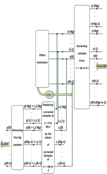
[image:5.595.316.538.112.472.2]Removing first Ng samples y(0) y(N-1) To FFT From S/P . . . . . . . . . . . . . . . . .
Fig. 5:Offset estimation and correction block for proposed scheme.
Fig. 5 demonstrates the CFO estimation and correction stage. In CFO estimation section, an extraction of samples with indices from indices of is first applied then estimation process takes place.
6.
SIMULATIONS AND RESULTS
This section discusses the simulations and results of the proposed scheme using MATLAB program. The performance of the proposed technique is first measured in terms of the match degree between the estimated normalized carrier frequency offset and the actual real value .
The system performance is also measured in terms of bit error rate (BER) against bit energy over noise average power spectral density curves. All curves use modulation of binary shift keying (BPSK).
Fig. 6 and Fig. 7 show the relation between the estimated normalized carrier frequency offset ( ) and the actual
Fig. 6:Estimated normalized carrier frequency offset versus the actual value in AWGN, using 8192
subcarriers
Fig. 6 shows the tradeoff between choosing the required number of OFDM symbols (L) in estimation process and the number of subcarriers (N) used in the system for the same ratio of . It is shown that, the straight line appears in case of using 8192 subcarriers with just one OFDM symbol but it needs 16-OFDM symbols in case of 64 subcarriers. That is because the number of samples used for estimation in case of N=8192 is enough but it decreases if N=64. So, increasing the number of required OFDM symbols is necessary in case of using lower number of orthogonal subcarriers as shown from figure.
Fig. 7:Estimated normalized carrier frequency offset versus the actual value in AWGN, using 8192 subcarriers for different guard interval's lengthes
Fig. 7 shows the tradeoff between choosing the required number of OFDM symbols (L) in estimation process and the ratio of used for the same number of subcarriers N=8192. In other words, Fig.7 shows the accuracy of proposed scheme for different values. Note that the straight line appears in case of for , and for and for . So, the simulation for proposed scheme shows good results for as mentioned before. Note also that, although N=8192, the accuracy of using and with L=1 degrades slightly than other
cases. So, to enhance the estimator's accuracy, we can increase the number of samples used in simulation by increasing the number of OFDM symbols used for estimation to be L=8 in case of and L=16 in case of as shown in the figure.
[image:6.595.319.546.202.412.2]Once the CFO value is estimated correctly, compensation process takes place. Figs. 8, 9 and 10 show the bit error rate curves versus for the proposed scheme using simulations in AWGN with orthogonal subcarriers. The comparisons were made with the theoretical curve of offset-free BPSK conventional technique.
Fig. 8:BER curves, N=8192 subcarriers and normalized carrier frequency offset of 1.4 in AWGN channel
In Fig. 8, a normalized CFO of was used for The simulated curves are identical with the offset-free theoretical curve except the case of using but increasing the number of OFDM symbols from to enhance the performance as shown in figure.
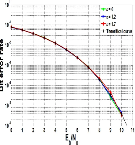
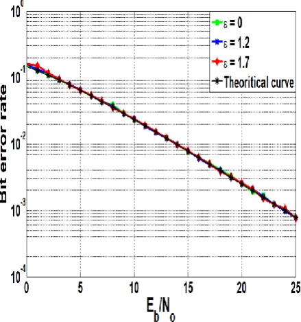
[image:6.595.58.283.414.597.2] [image:6.595.318.546.527.741.2]The bit error rate curves for different values of normalized carrier frequency offsets are shown in Fig. 9. As shown from the figure, the simulated curves of proposed scheme are identical with offset-free theoretical curve for all values that less than 8 as . The simulation uses 8-OFDM symbols in estimation process.
Fig. 10 shows the bit error rate with the same parameters as Fig. 9 except using . As shown, just one OFDM symbol is enough for the curves to be identical with the offset-free theoretical curve. That is because of the incensement of the number of samples in guard interval portion than the case of Fig. 9 that used . So, here just one OFDM symbol is needed for curves to be identical with theoretical curve leading to a decreasing in processing time than case of Fig. 9.
Fig. 10: BER curves, N=8192 subcarriers and Ng/N=1/4 using one OFDM symbol in AWGN channel
Figs. 11, 12 and 13 show the bit error rate curves versus for the proposed scheme where is the bit energy and is the noise energy. The simulation uses orthogonal subcarriers and . The comparisons were made with the theoretical curve of offset-free BPSK conventional technique. The simulations were made for Rayleigh multipath channel.
[image:7.595.318.537.73.311.2]As the CFO estimation needs to be within the uncorrupted guard interval, the number of uncorrupted samples that determined by the subtraction of maximum channel delay from the guard interval time is important in determining the system performance rather than all samples in guard interval portion.
Fig.11 shows the performance for maximum channel delay of and guard interval time of with different offset values. The figure shows an agreement of all curves with the offset-free theoretical one for L=16-OFDM symbols.
Fig. 11: BER curves, N=64 subcarriers and Ng/N=1/4 using 16-OFDM symbols in Rayleigh multipath
channel with maximum delay of
If the maximum channel delay was increased to be instead of , the number of uncorrupted samples would be decreased. Therefore, the number of OFDM symbols that used in estimation process should be increased to compensate for this reduction. Fig. 12 shows the relation between simulated proposed curves and offset-free theoretical curve if the maximum channel delay of and guard interval time of were used with L=16-OFDM symbols. This is a tolerated relation in which the mismatch between the two curves is neglected.
Fig. 12: BER curves, N=64 subcarriers and Ng/N=1/4 using 16-OFDM symbols in Rayleigh multipath
[image:7.595.58.281.246.486.2] [image:7.595.317.543.472.705.2]However, increasing the number of OFDM symbols will compensate for this small error. L=32 OFDM-symbols is sufficient for this compensation as shown in Fig. 13.
Fig. 13: BER curves, N=64 subcarriers and Ng/N=1/4 using 32-OFDM symbols in Rayleigh multipath
channel with maximum delay of
7.
CONCLUSIONS
The goal of this paper was to compensate for CFO that appeared in OFDM received signal. The motivation was to do that over a wide range of CFO. The proposed scheme used a new OFDM symbol structure in which the IFFT's output is extended by adding extra samples in time domain that permits expectation of CFO value at receiver side and also allows simple synchronization process using one-tap equalizer. Although the new OFDM symbol structure enhances the performance at the receiver over wide range of CFO, it slightly lowers the transmitted power and data rate as a result of adding extra samples at the transmitter side. From simulation results, it has been confirmed that the proposed scheme offer robustness and a performance improvement in both AWGN and Rayleigh multipath channels.
8.
REFERENCES
[1] Changha Yu, Jong In Park, and Seokho Yoon, "CFO Estimation Schemes Using the Cyclic Prefix for OFDM Systems in Non-Gaussian Noise Environments", The 2013 World Congress in Computer Science (WORLDCOMP'13) July 2013
[2] Yaojun Qiao, Zhansheng Wang, and Yuefeng Ji, "Blind frequency offset estimation based on cyclic prefix and virtual subcarriers in CO-OFDM system", Chinese optics letters, vol. 8, no. 9, September 10, 2010
[3] Ze Zhu†, Xiang Tang‡, JiZhang Zuo†, "Self-Cancellation Method of OFDM ICI", IEEE Wireless Communications, Networking and Mobile Computing, Oct. 2008.
[4] Fan junLe, Hu YongJiang, Chen ZiLi"A New ICI Self-Cancellation Method with Double Bandwidth Efficiency in OFDM Systems", IEEE International conference on communications and mobile computing, 2010.
[5] Wang yonggang, Zhu Shihua, Li Ying"A Method to Improve the Bandwidth Efficiency of Self ICI Cancellation in OFDM Systems", IEEE, Signal Processing, 6th International Conference, vol.2, 2002.
[6] Arvind Kumar, RajooPandey, "A bandwidth-efficient method for cancellation of ICI in OFDM systems by equalizing", International journal of electronics and communications, April 2008.
[7] Yuping Zhao, Jean-Damien Leclercq, and Sven-Gustav H¨aggman, "Intercarrier Interference Compression in OFDM Communication Systems by Using Correlative Coding", IEEE communications letters, vol. 2, no. 8, August 1998.
[8] Jae Yeun Yun, Sae-Young Chung, and Yong H. Lee, "Design of ICI Canceling Codes for OFDM Systems Based on Capacity Maximization", IEEE Signal processing letters, vol. 14, no. 3, March 2007.
[9] Paul H. MQose, "A Technique for Orthogonal Frequency Division Multiplexing Frequency Offset Correction", IEEE Transactions on communications, vol . 42, no. 10, October 1994.
[10]Jan-Jaap van de Beek, Magnus Sandell, and Per Ola BÄorjesson, "ML Estimation of Time and Frequency Offset in OFDM Systems", IEEE transactions on signal processing, vol. 45, no. 7, July 1997.
[11]Amine Laourine, Alex Stéphenne, and Sofiène Affes," A New OFDM Synchronization Symbol for Carrier Frequency Offset Estimation", IEEE signal processing letters, vol. 14, no. 5, May 2007.
[12]Ufuk Tureli, Hui Liu, and Michael D. Zoltowski, "OFDM blind carrier offset estimation", IEEE Trans. On Communications, December 1999.
[13]N Chen, M Tanaka and R Heaton, "OFDM Timing Synchronisation Under Multi-path Channels", Vehicular Technology Conference, The 57th IEEE Semiannual, vol.1, 2003.
[14]Yinsheng LIU, Zhenhui TAN , "Carrier Frequency Offset for OFDM Systems using Repetitive Patterns", RadioEngineering, vol. 21, no. 3, September 2012.
[15]Sameer S. M , R. V. Raja Kumar , "A Hybrid Synchronization Technique for the Frequency Offset Correction in OFDM", National Conference on Communications, Indian Institute of Technology, Kanpur, Jan. 2007.
[16]Xiaoli Ma, Georgios B. and Sergio Barbarossa, "Non Data Aided Frequency Offset and Channel Estimation in OFDM and Related Block Transmissions", IEEE International Conference, Communications, vol. 6, Jun. 2001
[17]Sandeep Kaur, Harjinder Singh, and Amandeep Singh Sappal, "Carrier Frequency Offset Estimation for OFDM Systems Using Time/Frequency Domain Techniques", International Journal of Advanced Research in Computer Science and Electronics Engineering, vol. 1, no. 2, April 2012.
The Department of Electrical and Computer Engineering, May 2003.
[19]Osesina Olukayode Isaac, Yafan Zhang, and Pagoti Shirisha, "OFDM Carrier Frequency Offset Estimation", Thesis, Electrical Engineering Department, Karlstad University, Sweden , June 2006.
[20]Seung Duk Choi, Jung Min Choi, and Jae Hong Lee, "An Initial Timing Offset Estimation Method for OFDM Systems in Rayleigh Fading Channel", IEEEVehicular Technology Conference, 2006.
[21]Tao Cui and Chintha Tellambura, "Joint Frequency Offset and Channel Estimation for OFDM Systems Using Pilot Symbols and Virtual Carriers", IEEE transactions on wireless communications, vol. 6, no. 4, April 2007.
[22]Homa Eghbali and Sami Muhaidat, "A new reduced-complexity detection scheme for zero-padded OFDM transmissions", EURASIP Journal on Wireless Communications and Networking, 2011.
[23]Sanjay Sharma, "Digital Signal Processing: with Matlab Programs", fifth edition, July 2009.
9.
AUTHOR’S PROFILE
Engineer: Shaimaa ElSayed Ibrahim ElTantawy received the B. S. degree (with Average Grade Very Good with honor degree) in Electric Engineering from Banha University,
Shobra branch College, Egypt and the M.S. degree in Electrical Communication from Al-Azhar University in Cairo, Egypt. Currently, she is a teaching assistant at Department of Electronic Engineering and Communication Technology (EECT) in Modern Academy in Ma'adi, Egypt. Area of interest is electronics and communication field especially multi-carrier transmission through wireless communication channel under the effect of Rayleigh fading.
Professor: K.A. ElBarbary received the B. S. degree (with Average Grade Very Good) in Electric Engineering from Military Technical College, Egypt , the M.S. degree in Electric Engineering from Military Technical College, Egypt, the Ph.D. degree in Communications from George Washington University, Washington DC, USA, in 1981, 1986 and 1993, respectively. He was faculty member at Military Technical College, Egypt in the Electric Engineering Department (Chair of communications and Electronic warfare) (1994-2010). There he became a professor of Electric Engineering (2009), Head of Electronic Warfare Engineering Department (2000), and Head of Electrical Engineering Department (2009). He has been a professor of signal and systems and Communications at Suez Canal University, Egypt in Electric Engineering Department. Currently he is the Head of Electric Engineering Department, Suez Canal University, Egypt. His research interests include Statistical signal and array processing and related applications in communications, radar, Electronic Intelligence, Multi user Detectors and wide band communication systems.