Comparison of Experimental and Analytical
Methods of Obtaining Stability Lobe Diagram for
High Speed Machining Processes – A Review
Pal Pandian P1, Dr.Prabhu Raja V2
1
Associate Professor, Department of Mechanical Engineering, Christ University Faculty of Engineering, Bangalore, Karnataka, India.
2
Associate Professor, Department of Mechanical Engineering, PSG College of Technology, Coimbatore, Tamilnadu, India
Abstract: Chatter is a complicated problem faced by machine tool operators. Chatter is a self-excited vibration that can occur during machining operations. This is an undesirable phenomenon which limits the productivity of the machine. A lot of techniques have been developed to control the chatter.
Stability lobe diagram is an effective tool which helps the operator to select specific spindle speeds during production to avoid chatter in machine. Stability lobes are plotted against axial depth of cut vs. spindle speed, which shows a boundary between stable and unstable cutting regions. Numerous experimental and analytical techniques have been developed to establish stability lobe diagram. This paper presents a review on experimental and analytical methods of obtaining stability lobe diagram in high speed milling operation.
Keywords: High speed milling, stability lobe diagram, FRF, Fourier transform, chatter.
I. INTRODUCTION
High speed milling operations are commonly used in present day manufacturing systems for increased production and high precision manufacturing. With the development of high speed machining (HSM), many parts which are thin walled, flexible and low rigid has become easy to manufacture. A large number of parts of such kind are manufactured in CNC machines with end milling tool. During high speed machining, the milling of thin walled plate leads to a lot of dynamic problems. The main dynamic problem is self-excited vibration called regenerative chatter.
Chatter is a self-excited vibration that can occur during machining operations and becomes a common limitation to productivity and part quality [1]. This phenomenon has several negative effects such as poor surface quality, unacceptable accuracy excessive noise and tool wear, machine tool damage, reduced Material Removal rate (MRR), increased costs in terms of time, materials and energy. In workshops, machine tool operators often select conservative cutting parameters to avoid chatter. Moreover, in some cases, additional manual operations are required to clean chatter marks left on the part surface.
The studies on chatter can go back to the 1950s with Tobias Tlusty and Polacek and Merit, who explained the regenerative chatter in orthogonal cutting and developed the two-dimensional stability lobe theory. They simultaneously made the remarkable discovery that the main source of self-excited regenerative vibration/chatter was not related to the presence of negative process damping as was previously assumed. However, it is related to the structural dynamics of the machine tool-workpiece system and the feedback response between subsequent cuts. Though, a pioneering research, their model is only applicable to orthogonal metal cutting where the directional dynamic milling coefficients are constant and not periodic.
A. Vibration during machining
This type of vibration brings the system to instability and is the most undesirable and the least controllable. For this reason, chatter has been a popular topic for academic and industrial research.
The regenerative effect is based on the fact that the tool cuts a surface already cut during the previous revolution, the cutting force varies as well as the chip thickness, leading to the time delay of the dynamic equation. The classical regenerative vibration model plays an essential role in machine tool vibrations. For most cases taking the regenerative effect into account, the structural mode coupling effect is neglected. The frequency response function (FRF) matrix of the most flexible structure (machine–tool) is assumed diagonal, i.e. the vibration modes in different directions are assumed uncoupled and the cross FRFs are considered as zeros. For the frequency domain methods [18], such simplification leads to the analytic expression of the solution [19]. There are also many other methods handling the stability prediction of the regenerative chatter besides the frequency domain methods, such as the time domain methods[30], the numerical simulation method [36], the semi-discretization method [20], the Lambert function based method [21], the Chebyshev collocation method [22], the full-discretization method [23], etc. chatter can occur in different metal removal processes: milling [44], turning, drilling [24], boring [25], broaching [26] and grinding.
chatter occurrence has several negative effects:
1) Poor surface quality.
2) Unacceptable inaccuracy.
3) Excessive noise.
4) Disproportionate tool wear.
5) Machine tool damage.
6) Reduced material removal rate (MRR).
7) Increased costs in terms of production time.
8) Waste of materials.
9) Waste of energy.
10) Environmental impact in terms of materials and energy.
11) Costs of recycling, reprocessing or dumping non-valid final parts to recycling points.
B. Stability lobe diagram
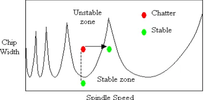
The two-dimensional stability lobe theory deals with the stability of solutions for dynamical cutting systems, which usually stands for the spindle speed and axial depth. Fig.1 shows an example of stability lobe diagram. As a function of these two cutting parameters, the border between a stable cut (i.e., chatter-free) and an unstable one (i.e., with chatter) can be visualized in a chart called stability lobes diagram (SLD). 3D stability lobes were later established considering radial depth of cut as another parameter [15][16]. In the middle of the 1990s, Altintas and Budak[2] presented an analytical form of the stability lobe theory for milling. Both of these stability lobe theories can help to select the appropriate cutting parameters of the spindle speed and axial depth to avoid chatter in machining processes.
[image:3.612.208.410.594.693.2]Stability studies have two important research approaches. On the one hand, many authors have studied it through machine behaviour, assuming a rigid workpiece. The tool tip transfer function is elaborated through models or experimental approaches. On the other hand, most of the previous models made the assumption that spindle-tool set dynamics do not change over the full spindle speed range. This assumption needs to be reconsidered in HSM, where gyroscopic moments and centrifugal forces on both bearings and spindle shaft induce spindle speed dependent dynamics changes. Few studies were also done considering the flexibility of workpiece [17]. For accurate dynamics prediction, spindle speed-dependent dynamics must be evaluated. Figure 1, shows the SLD curve for stable and unstable zones.
Faassen et al.[3] And Schmitz et al.[4] considered spindle speed dependent dynamics on the basis of experimental transfer function identification at different spindle speeds. Their method uses impulse hammer excitation and contact-free (capacitive probe) response measurement of a rotating tool at different discrete spindle speeds. Experimental results revealed speed dependent variations in spindle dynamics and hence in the stability limit. However, many conventional testing techniques prove unsuccessful at determining spindle behavior during speed rotation. Indeed, in an experimental modal analysis of a high-speed rotating shaft, the location of the hammer impact point and the sensor measurement point is not properly defined.
The steps involved in the prediction of stability lobe diagram [11] are given below: Initially, the dynamic characteristics and milling process parameters of the machine-tool-workpiece system are obtained using experimental analysis. Then the frequency response function is determined after selecting the natural frequency and exciting frequency. Using FRF, stability milling limits are estimated and the stability lobe diagram is obtained. Prediction of lobes can be done by analytical method, semi analytical method and experimental method.
II. EXPERIMENTAL METHOD
[image:4.612.183.384.318.426.2]Experimental method aims to obtain stability lobe diagram by conducting a series of experiments on workpiece by machining it using a milling machine tool. Tonshoff [12] showed that, while machining at a certain depth of cut along the tool path, forced vibrations turn into self-excited vibrations and the milling process becomes unstable. This principle is used in various experiments to determine chatter.
Figure 2. Experimental setup for finding stability lobe diagram.[8]
[image:4.612.204.405.585.701.2]Guillem Quintana[8] proposed a method of obtaining stability lobe diagram completely by experimental method as shown in figure 2. A tapered workpiece was machined in a milling machine tool. While machining at a particular speed, the axial depth of cut increases owing to the tapered geometry and after certain point, chatter occurs. Chatter is detected if the energy of the measured signal exceeds a certain threshold value. The signals from microphone were recorded in PC and analyzed for chatter frequency. Various software such as labview, cutpro [7], metalmax are used in monitoring and recording the data from microphone. A suitable DAQ assist was used for acquiring the sound signal during machining. The Fast Fourier Transform [9] (FFT) was calculated from audio signal to obtain frequency domain. The graph shows high sound level during chatter period and low amplitudes for chatter free operations. The critical frequency levels are noted in all experiment cases and stability lobe diagram is plotted based on the experimental results. This procedure is repeated for various depth of cut and spindle speed combinations.
Maximum Y travel was directly extracted from the machine tool screen when chatter was detected by the operator and the machine tool was stopped. Maximum axial depth of cut can be calculated by applying trigonometric principles since the work-piece inclination is known. The operator had to decide when to stop the machine following his own criterion based on the machining sound. Expert operator can achieve good results applying this methodology as is demonstrated along this work. Figure 3, shows SLD marked on machined workpiece surface. The experimental method of determining lobes involves lot of time and cost and in order to reduce the experimentation effort, few researches were carried out to determine lobes using semi analytical method.
III. SEMIANALYTICALMETHOD
In this method most of the parameters required to obtain stability lobes are calculated analytically. The modal parameters of spindle/tool holder/tool systems are obtained experimentally using impulse hammer test [6]. Figure.4 shows the experimental set up for modal analysis of spindle/tool holder/tool which is multi DOF system. This method helps us to determine the modal parameters of system which are then used to find the transfer functions. In this method an accelerometer is mounted on the tool to sense vibration on tool. The accelerometer is connected to a DAQ card which receives signals and converts it to digital form so that the PC can read those signals. The DAQ is connected to PC and software are used to monitor and record the signals. An impulse hammer is used to make an impact in the tool which is also connected to DAQ and PC to measure impact provided by hammer. With this method a range of frequencies are excited that contain the natural modes of the system. In order to obtain the natural frequency of spindle/tool holder/tool system, an impulse needs to be generated and this can be given with a short impact using a hammer. To choose the appropriate hammer and sensor, it is necessary to consider the mass, the stiffness and the material of the structure [8].
Since the impulse generated is recorded in software, FRF of spindle/tool holder/ tool system can be calculated with help of recorded readings. The stability lobe depends on the FRF of above system and hence it is desirable to extract FRF of spindle/tool holder/ tool system using experimental method. Then the FRF obtained can be used to calculate stability lobe diagram.
Recent developments in sensors and computers have led to the rise of analytical–experimental methods and computer simulation analyses. In manufacturing automation, Altintas [5] explains a widely known analytical–experimental method based on the use of an impact hammer instrumented with a piezo electric force transducer. Transfer functions of existing multi-degree-of-freedom (MDOF) systems can be identified by structural dynamic tests. In this case, to obtain the transfer function, the structure is excited with an impact hammer and the resulting vibrations are measured with displacement, velocity or acceleration sensors. CUTPRO software implifies the test and offers automatic predictions of the SLD. Another software program called Harmonizer scans the sound of the cutting process with a microphone and chatter is detected if the energy of the measured sound signal exceeds a certain threshold.
[image:5.612.196.399.332.463.2]In experimental methods the accuracy of result completely depends on sensors used in experiment. Any errors in sensors cause a wrong prediction of lobes. Therefore selection and placement of sensors in tool also play an important role in obtaining accurate lobes. The contact type sensors used for detecting vibration are Accelerometer, Piezo electric sensor, proximity sensor and Inductive sensor, while the non-contact type sensors include Fiber optical sensor, Laser sensor, Eddy current sensor and capacitive sensor.
Fixing the contact type sensors in the system will also contribute to some errors in measurement. Figure. 5 shows the frequency characteristics based on sensor fixing ways. The vibration induced during machining also affects the performance of sensor since it is in direct contact with the vibrating system.
Figure 5. Frequency characteristics on sensor fixing ways
So it is important to choose the setup that best meets the required frequency range. Also positional errors may also occur when using the contact type sensor. Hence, non contact type sensors can be used for obtaining better results. The semi analytical methods have reduced the need for experimentation to a certain extent so that lobes could be predicted in a shorter time. Resorting to analytical methods without experimentation to determine the stability lobes will further reduce the time and effort.
IV. ANALYTICALMETHOD
Numerous research works are being carried out for determining the stability of spindle during thin wall machining [27-31,43]. With help of this method various behaviors of machine tool structures were predicted before they were constructed. Altintas and Budak [4] proposed a model which is widely used in present practice. The aim of analytical approach is to obtain the transfer functions of structure, which is required in the stability model and to eliminate the need for series of experimental impact testing at various points on a thin walled workpiece. The work done by these authors are based on a chatter stability model which shows the periodic cutting forces acting on cutter and workpiece [13].
Figure 6, shows the dynamic milling force model showing the undulation on machined surface and each tooth removes the undulation caused by the previous tooth [10]. Based on this model, equations were arrived to find the chatter free axial depth of cut. Using the equations arrived in analytical approach the stability lobes were plotted [14].
While the research work related to SLD was carried out based on analytical approach it was found that the dynamic characteristics of spindle/tool-holder/tool were also accounting for the behavior of system [23]. The authors have shown that the spindle dynamics depend on a large number of factors, including holder characteristics , spindle shaft geometry and drawbar force and the stiffness and damping provided by the bearings. Most of these factors are independent of the spindle speed, but bearing stiffness depends on changes in load and spindle. So the equations were modified to account the multiple mode characteristics. Cutting force nonlinearities were also taken into account by some investigators [36,37,41]. The workpiece
[image:6.612.212.404.485.617.2]dynamics affecting stability limit during machining were also studied by authors like Erhan Budak[38]. There are also many investigators who used finite element analysis (FEA) for stability simulation. The finite element approaches were mainly used to find the workpiece FRF and establishing the transfer function based on the FEA [42] results. Mahnama and Movahhedy [32] presented an approach based on FEM for predicting for machining chatter. Garitaonandia et al. [33] propose a dynamic model of a centreless grinding machine based on FEM. Biermann et al. developed a finite element (FE) model for the workpiece coupled with geometric milling simulation to compute regenerative workpiece vibrations in five-axis milling of turbine blades. Seguy et al. [34] also propose the use of the FEM to calculate 3D stability lobes for thin wall machining. Ostasevicius[35] presented a FEM based modal analysis on cutting tools for reducing vibrations during cutting operations. Svetan Ratchev [39,40] presented an approach using FEM for determining the workpiece deflections during machining and it’s transformations. This eliminates the need for carrying out experiments on workpiece to obtain FRF of workpiece.
Thus the analytical approach aided with numerical method eliminates the need for experimentation and saves the time and cost involved in determining the stability lobes.
V. CONCLUSIONS
In this paper, experimental and analytical methods of determining stability lobes are compared. Researchers have predicted chatter during machining and established 2D stability lobe diagrams plotted between axial depths of cut and spindle speed. Since the radial depth of cut also plays a part in stability, works are done to establish 3D stability lobe diagrams. Stability lobe diagram is helpful in selecting the proper spindle speeds for chatter free machining. The experimental method involves lot of cost and time, whereas the analytical method eliminates need for experimentation. The stability lobes predicted by analytical method needs to be validated experimentally to ensure the accuracy of results.
Few research works have considered spindle/tool holder/tool system as rigid and considered workpiece as non-rigid element. Later, few authors have considered workpiece as rigid and spindle/tool holder/tool systems as non-rigid elements, but while machining thin wall structures neither workpiece nor spindle/tool holder/tool system is rigid. There is a need to integrate the spindle workpiece model to account for the vibratory interaction between the two systems and hence predict the stability lobes more accurately.
REFERENCES
[1] F. W. Taylor, On the art of cutting metals, Transactions of the American Society of Mechanical Engineers, 28, 1907, pp. 31–350. [2] Y.Altintas, E.Budak, Analytical prediction of stability lobe in milling, CIRPAnnals44 (1) (1995)357–362.
[3] P.H.Faassen, N.vandeWouw, J.A.J.Oosterling, H.Nijmeijer, Prediction of regenerative chatter by modeling and analysis of high-speed milling,
International Journal of Machine Tools and Manufacture 43(2003)1437–1446.
[4] T.Schmitz, J.Ziegert, C.Stanislaus, A method for predicting chatter stability for systems with speed-dependent spindle dynamics, Society of Manufacturing Engineers Technical Paper TPO4PUB182, Transactions of the NAMRI/SME 3 2(2004) 17–24.
[5] Y. Altintas, Manufacturing Automation, Cambridge University Press, New York, NY (2000).\
[6] E. Solis, C.R. Peres, J.E.Jimenez, J.R.Alique J.C. Monje, A new analytical experimental method for the identification of stability lobes in high speed milling. International journal of machine tools and manufacture,(2004).
[7] Manufacturing Automation Laboratories Inc. Cutpro7. http://www.malinc.com,2004.
[8] Guillem Quintana, Sound mapping for identification of stability lobe diagrams in milling processes, International journal of machine tools and manufacture,(2009).
[9] O.B. Adetoro, P.H. Wen, W.M. Sim, R. Vepa, Stability Lobes Prediction in Thin Wall Machining, Proceedings of the World Congress on Engineering 2009 vol I, London, UK.
[10] V. Gagnol, B.C. Bouzgarrou, P.Ray, C. Barra, Model based chatter stability prediction for high speed spindles. International journal of machine tools and manufacture,(2006).
[11] W.X. Tang, Q.H. Song, S.Q. yu, S.S. Sun, B.B. Li, B. Du, X.Ai. Prediction of chatter stability in high speed finishing end milling considering multi-mode dynamics. Journal of Materials Processing Technology 209(2009) 2585-2591
[12] Dornfeld, Precision Manufacturing, first ed., Springer, NewYork, NY, 2007.
[13] I. Mane, V. Gagnol, B.C. Bouzgarrou, P. Ray, Stability based spindle speed control during flexible workpiece high speed milling. International journal of machine tools and manufacture,(2007).
[14] Machining Dynamics – Frequency response for improved productivity. Springer edition ISBN 978-0-387-09644-5, 2009.
[15] Aijun Tang, Zhanquiang Liu. Three dimensional stability lobe and maximum material removal rate in end milling of thin walled plate. International Journal of Advanced Manufacturing Technology, 2009.
[16] Vincent Thevenot, Lionel Arnaud, Gilles Dessein, Gilles Cazenave, Larroche, Integration of dynamic behavior variations in the stability lobes method: 3d lobes construction and application to thin walled structure milling, International Journal of Advanced Manufacturing Technology, 2006.
[17] U. Bravo, O. Altuzarra, L.N. Lopes de Lacalle, J.A. Sanchez, F.J. Campa, Stability limits of milling considering the flexibility of the workpiece and the machine. International journal of machine tools and manufacture,(2005).
[19] M. Wiercigroch, E. Budak, Sources of nonlinearities, chatter generation and suppression in metal cutting, Philosophical Transactions of the Royal Society of London Series A: Mathematical, Physical and Engineering Sciences 359 (1781) (2001) 663.
[20] T. Insperger, G. Stepan, Semi-discretization method for delayed systems, International Journal for Numerical Methods in Engineering 55 (5) (2002) 503–518.
[21] F.MAGHAMI ASL, A.GALIP ULSOY, Analysis of a system of linear delay differential equations, Journal of Dynamic Systems, Measurement, and Control 125 (2) (2003) 215–223.
[22] E. Butcher, O. Bobrenkov, E. Bueler, P. Nindujarla, Analysis of milling stability by the Chebyshev collocation method: algorithm and optimal stable immersion levels, Journal of Computational and Nonlinear Dynamics 4 (3) (2009) 1–12.
[23] Y. Ding, L. Zhu, X. Zhang, H. Ding, A full-discretization method for prediction of milling stability, International Journal of Machine Tools and Manufacture 50 (5) (2010) 502–509.
[24] T. Arvajeh, F. Ismail, Machining stability in high-speed drilling—part 1: modeling vibration stability in bending. International Journal of Machine Tools and Manufacture 46((12-13)) (2006) 1563–157259.
[25] F. Atabey, I. Lazoglu, Y. Altintas, Mechanics of boring processes—part I, International Journal of Machine Tools and Manufacture 43 (5) (2003/4) 463–476.
[26] D.A. Axinte, N. Gindy, K. Fox, I. Unanue, Process monitoring to assist the workpiece surface quality in machining, International Journal of Machine Tools and Manufacture 44 (10) (2004/8) 1091–1108.
[27] B.P. Mann, K.A. Young, T.L. Schmitz, D.N. Dilley, Simultaneous Stability and Surface Location Error Predictions in Milling, Journal of Manufacturing Science and Engineering, Transactions of the ASME 2005 127 (2005) 446–453368.
[28] V. Gagnol, B.C. Bouzgarrou, P. Ray, C. Barra, Tekniker (Eds.), Methodology for optimal choice of the HSM spindle range, in: Proceedings of the Sixth International Conference on High Speed Machining, 21–22 March 2007, San Sebastian, Spain, 2007.
[29] C. Brecher, M. Esser, F. Paepenmuller, CIRP (Eds.), Motor spindles for HPC, in: Proceedings on Testing and Chatter Simulation, 12–13 June 2006, Vancouver, British Columbia, Canada.
[30] C. Brecher, M. Esser, University of Metz (Eds.), Process stability in high speed machining: test and simulation of motor spindle systems, in: Proceedings of the Fifth International Conference on High Speed Machining, 14–16 March 2006, Metz, France, 2006.
[31] C. Brecher, M. Esser, Tekniker (Eds.), Stability prediction: advances and current restrictions, in: Proceedings of the Sixth International Conference on High Speed Machining, 21–22 March 2007, San Sebastian, Spain 2007.
[32] M. Mahnama, M.R. Movahhedy, Prediction of machining chatter based on FEM simulation of chip formation under dynamic conditions,
International ournal of Machine Tools and Manufacture 50 (7) (2010) 611–620.
[33] I. Garitaonandia, M.H. Fernandes, J. Albizuri, Dynamic model of a centerless grinding machine based on an updated FE model, International Journal of Machine Tools and Manufacture 48 (7–8) (2008) 832–840.
[34] S. Seguy, F.J. Campa, L.N.L. de Lacalla, L. Arnaud, G. Dessein, G. Aramendi Toolpath dependent stability lobes for the milling of thin-walled parts, International Journal of Machining and Machinability of Materials 4 (4) (2008) 377–392.
[35] V.Ostasevicius , R. Gaidys , J. Rimkeviciene , R. Dauksevicius, An approac h based on tool mode control for surface roughness reduction in high-frequency vibration cutting. Journal of Sound and Vibration 329 (2010) 4866–4879.
[36] Hamed Moradi, Mohammad R. Movahhedy n, Gholamreza Vossoughi. Dynamics of regenerative chatter and internal resonance in milling process with structural and cutting force nonlinearities, Journal of Sound and Vibration 331 (2012) 3844–3865.
[37] Hamed Moradi, Firooz Bakhtiari-Nejad, Mohammad R. Movahhedy , Gholamreza Vossoughi, Stability improvement and regenerative chatter suppression in nonlinear milling process via tunable vibration absorber. Journal of Sound and Vibration 331 (2012) 4668–469.
[38] Erhan Budak, L.Taner Tunc, Salih Alan, H. Nevzat Ozguven. Prediction of workpiece dynamics and its effects on chatter stability in milling, CIRP Annals - Manufacturing Technology 61 (2012) 339–34.
[39] Svetan Ratchev, Stan Nikov, Idir Moualek. Material removal simulation of peripheral millingof thin wall low-rigidity structures using FEA. Advances in Engineering Software 35 (2004) 481–491
[40] Dong Hui-yue,KE Ying-lin, Study on Machining Deformation of Aircraft Monolithic Component by FEM and Experiment. CHINESE JOURNAL OF AERONAUTICS August 2006, Vol. 19 No. .
[41] Erol Turkes , Sezan Orak , Suleyman Neseli , Suleyman Yaldiz, A new process damping model for chatter vibration . Measurement 44 (2011) 1342–134.
[42] Jitender K. Rai , Paul Xirouchakis, Finite element method based machining simulation environment for analyzing part errors induced during milling of thin-walled components,International Journal of Machine Tools & Manufacture 48 (2011) 629–643.
[43] Xiao Jian Zhang, Cai Hua Xiong, Ye Ding , Ming Jun Feng, You Lun Xiong, Milling stability analysis with simultaneously considering the structural mode coupling effect and regenerative effect. International Journal of Machine Tools & Manufacture 53 (2012) 127–140
![Figure 2. Experimental setup for finding stability lobe diagram. [8]](https://thumb-us.123doks.com/thumbv2/123dok_us/8585948.862406/4.612.183.384.318.426/figure-experimental-setup-finding-stability-lobe-diagram.webp)

![Figure 6, shows the dynamic milling force model showing the undulation on machined surface and each tooth removes the undulation caused by the previous tooth [10]](https://thumb-us.123doks.com/thumbv2/123dok_us/8585948.862406/6.612.212.404.485.617/figure-showing-undulation-machined-surface-removes-undulation-previous.webp)
