High Power Direct Drive WECS Using Fuzzy
Logic Controller
Prudhvi.Golla1, A.Satyanarayana2
1
Under-Graduate Student , 2Head of Department-E.E.E VKR&VNB Engg College,Gudivada
Andhra Pradesh,India
Abstract— Because of energy shortage and environment pollution, the renewable energy, especially wind energy has become more and more considerable all over the world. Direct drive wind energy conversion systems based on multipole permanent magnet synchronous generator (PMSG) have some advantages such as no gearbox, high power density, high precision and easy to control. In our research project, a 2MW direct drive wind energy conversion system is developed. In this paper, an efficient experimental method for high power converter is presented. A large circulating current flows in the converter, but only a small part of the current caused by the losses of the converter flows into the grid. The method can save a lot of energy when the converter is tested and the experiment can
be done in the micro grid. The method can test the main stage, drive circuit, protect circuit and some parts of control circuit. Modeling and control scheme of the efficient experimental method are introduced in this paper, as well as the control scheme of the grid side converter.
Keywords—Wind energy conversion, Circulating current, PWM, SVM
I. INTRODUCTION
Wind energy conversion systems are available in a wide range of sizes and can fit almost any application where power is needed. This paper is designed to briefly explain the applications for which wind power is currently best suited in international applications. In recent decades, the industry has been perfecting the wind turbine to convert the power of the wind into electricity. The wind turbine has many advantages that make it an attractive energy source, especially in parts of the world where the transmission infra structure is not fully developed. It is modular and can be installed relatively quickly, so it is easy to match electricity supply and demand. Since, wind is an unreliable resource, which is likely to vary over time. Wind speeds are not predictable, except as an approximation. User loads are also unpredictable, which keep changing every hour. When a wind turbine operates a self-excited induction generator, a fall in the turbine speed of the wind power plant results due to an increase in the load connected to the self-excited induction generator (SEIG). If the load on the SEIG for a constant wind speed is increased, its speed decreases and hence the voltage and frequency are decreased. Similarly an increase in wind speed for a constant load will lead to the voltage and frequency shoot up. The decrease in voltage and frequency is undesirable and a sharp increase in voltage and frequency may be harmful for the connected appliances. a number of control strategies have been reported in the literature. Load control appears to be one such strategy. To avoid the above discussed problems a balance between input power and output power must be set. A controlled secondary load connected in parallel with the main load can achieve this. The secondary load is switched whenever there is an unbalance between the input and output powers. Direct drive wind energy conversion systems based on multipole permanent magnet synchronous generator (PMSG) have some advantages such as no gearbox, high power density, high precision and easy to control. Three different schemes for generator are given in order to obtain an optimum rating of a PMSG and its power converter. In our research project, a direct drive wind energy conversion system is developed. The traditional way to test the converter is using resistance loads. An efficient experimental method can collect the energy which is wasting on the loads. A large circulating current flows in the converter, but only a small part of the current caused by the losses of the converter flows into the grid. The method can save a lot of energy when the converter is tested and the experiment can be done in the micro grid. The method can test the main stage, drive circuit, protect circuit and some parts of control circuit. The method has some advantages, such as low power losses and easy to control. Modeling and control scheme of the efficient experimental method are introduced in this paper, as well as the control scheme of the grid side converter.
II. SYSTEM CONFIGURATIONS
871
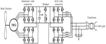
the generator converts it to the electrical power. Then the power electronics equipment converts it to the high quality power and controls the rotor speed of the generator. Two multiple converters which are connected in parallel in the both sides are used in this high power situation. Multiple techniques can reduce the current of each converter. So it can increase the reliability of the converter. At the same time, it can reduce the ripple of the output current. So the output filter inductor L and capacitor C can be reduced observably.Fig. 1. The structure of direct drive wind energy conversion system
III. PROTOTYPE DESCRIPTION AND CONTROL IMPLEMENTATION
A. Permanent-Magnet Generator And Grid Connection
The permanent-magnet synchronous generator used was 3 kW, 220 V (wye three-phase stator winding), and 375 r/min (16 poles). NdFeB magnets provide proper flux density in the air gap. The winding resistance and inductance obtained through laboratory tests) are, respectively, RS = 2.4Ω and LS = 51mH. Rotor position is obtained through an encoder giving 1500 pulses
per revolution. The frequency converter consists of two back-to-back insulated gate bipolar transistors (IGBTs) bridges; the one connected to the generator works as a pulse rectifier; the other one, connected to the grid, works as a pulse width-modulation (PWM) inverter. Both of them have six IGBTs (600 V, 15 A). The dc link incorporates a 600-μF, 800-V capacitor. An inductive filter has been designed to limit harmonic current injection into the grid complying with IEC 61000-3-2 regulations. The switching frequency was 3 kHz. A transformer (400/230 V) was used for grid connection to allow the operation of the inverter with leading power factor. The resulting inductance in the grid connection, including the transformer short circuit reactance, was 4 mH.
B. Wind Turbine Emulation
The emulation of the wind turbine is implemented by means of a dc motor drive with torque control. In the prototype, a 4.4 kW, 1980 r/min dc motor was used. A computer program reads the wind input file, which has been obtained in different test conditions, and calculates the wind turbine torque, by taking into account wind velocity, turbine rotational speed, and the wind turbine power coefficient curve (a lookup table in the computer was used). The control algorithms for turbine emulation are implemented in a control board dSPACE DS1102. This board is a commercial system designed for rapid prototyping of real control algorithms; it is based on the Texas Instruments TMS320C31 floating-point DSP and includes four A/D input channels, 16 digital I/O channels, an eight-channel capture/compare unit, and a six-channel PWM generation module. The DS1102 board is hosted by a personal computer.
C. Power Converter Control
Real-time control was implemented in two dSPACE boards, one for each power converter. The sampling time for generator control (175 μs) is longer than that of the grid inverter control, as the former provides the turbine torque reference besides the corresponding PWM pulse signals. Also, the generator controller board has to obtain the reference angle position and the generator speed from the pulse encoder signals. Inverter control calculations are simpler, as the reference angle needed for vector control is obtained from the line voltage zero crossing that allows a reduction of the sampling time (130 μs). Hall sensors are used to capture necessary current and voltage signals.
IV. FUZZY CONTROL OF SECONDARY LOAD
variable for the closed loop control and the power of a resistive secondary load as the controlled variable. The purpose of this secondary load is to quickly absorb any excess wind power, thus helping to control the system frequency. The secondary load is a variable, three phase resistive load. The eight three-phase resistors are connected in series with eight ideal switches. Simulating forced commutated power electronic switches. The load variation uses an eight bit binary progression so that load power can be varied in steps from 0 to 255*(Power per step) A number of reports are available dealing with the application of Fuzzy controllers.
FIG. 2 BLOCK DIAGRAM OF A WIND ENERGY CONVERSION SYSTEM WITH SECONDARY LOAD
[image:4.612.237.389.296.408.2]V. FUZZY LOAD REGULATOR MODEL
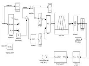
Fig.3. SIMULINK model for Fuzzy Load Regulator Model
Fig. 3 shows the SIMULINK model of fuzzy load regulator. The fuzzy controller is basically a fuzzy P-I controller. The regulators output represents the desired power of the secondary load. The frequency regulator input is represented by the voltage frequency. There is used a three-phase Phase Locked Loop (PLL) system to measure the frequency of the three-phase voltage of the network. Therefore, the measured frequency is compared to the reference frequency in order to obtain the frequency error. The fuzzy controller adopts two input variables the error in frequency ‘ef’ and the change in this error ,df’ which is related to the derivative of error. Since the fuzzy controller is basically an input-output static nonlinear mapping, the output of fuzzy controller is a function of error in frequency (ef) and the derivative of this error (df).
so the output of fuzzy controller can be written in the form.
1
( )
2(
)
DP
K ef
K df
(1)Where K1 and K2 are nonlinear coefficients or gain factors.
The output of the integrator is given as
1
(
)
2(
)
P
K
ef dt
K ef
(2)After the integration of fuzzy controller output (DP) The obtained signal (P) is an analogue signal which is fed to the “Pulse Decoder” and “Sampling System”. The pulse decoder and sampling system circuit decodes the scalar input 'code' into three phase eight bit binary pulses.
A. Fuzzy Controller Membership Functions And Shapes
873
[image:5.612.224.395.135.354.2]B. Fuzzy Rule Base
[image:5.612.170.393.467.692.2]Table I shows the corresponding rule base table for the fuzzy controller. The top row and left column of the matrix indicate the fuzzy sets of the variables (ef) and (df), respectively, and the membership functions of the output variable (DP) are shown in the body of the matrix.
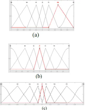
Fig. 4 Degree of Membership of (a) Frequency error (b) derivative of frequency error(c) output variable (DP (a) (b)
C. Defuzzification
The output of fuzzy controller is changed into a crisp value by defuzzifier. Here fuzzy set representing the controller output is defuzzified using the Centre of Area (COA) method.
VI.SIMULATIONANDEXPERIMENTALRESULTS
MATLAB/SIMULINK is used in the simulation. The dc-link capacitor C is 15mF and the filter inductor L is 0.4mH. The switching frequency is 2.5 k Hz. Simulation results are shown in Figs.
Fig ; sending end voltage, current, active and reactive power waveforms
[image:5.612.232.380.475.594.2] [image:5.612.212.397.602.690.2]VII. CONCLUSION
This work shows the performance of an efficient experimental method for high power converter which is used in direct drive wind energy conversion systems. A large circulating current flows in the converter, but only a small part of the current caused by the losses of the converter flows into the grid. The method can save a lot of energy when the converter is tested and the experiment can be done in the micro grid. The method can test the main stage, drive circuit, and protect circuit and some parts of control circuit. Modeling and control scheme of the efficient experimental method are introduced in this paper, as well as the control scheme of the grid side converter.
REFERENCES
[1] Ye Hangye. The Control Technology of Wind Energy Conversion Systems.Beijing, China: Mechanical Industries Publishing Company, 2002.
[2] M. Chinchilla, S. Arnaltes and J. C. Burgos, “Control of permanent-magnet generators applied to variable-speed windenergy systems connected to the grid”, IEEE Transactions on Energy Conversion, Vol. 21, No. 1, March 2006, pp. 130–135.
[3] H. Polinder, F. F. A. van der Pijl, G. de Vilder, and P. J. Tavner, “Comparison of direct-drive and geared generator concepts for wind turbines”, IEEE Transactions on Energy Conversion, Vol. 21, No. 3, September 2006, pp. 725–733.
[4] A. Grauers, “Design of direct driven permanent magnet generators for wind turbines”, M.S. thesis, Chalmers Univ. Technol., Goteborg, Sweden, 1996. [5] S. H. Ko, S. R. Lee, H. Dehbonei and C. V. Nayar., “Application of voltage and current-controlled voltage source inverters for distributed generation systems”, IEEE Transactions on Energy Conversion, Vol. 21, No. 3, September 2006, pp. 782–792.
[6] K. Xing, F. C. Lee, D. Borojevic and Z. Ye, “Interleaved PWM with discontinuous space-vector modulation”, IEEE Transactions on Power Electronics, Vol. 14, No. 5, September 1999, pp. 906–917.
[7] D. Ramirez, C. Veganzones, and F. Blazquez, “Adaptation of floating point DSP-based technology for small variable-speed wind turbine”, IEEE Transactions on Energy Conversion, Vol. 22, No. 2, June 2007, pp.376–382.
[8] Wang Zhaoan. Power electronic technology. Beijing, China: Mechanical Industries Publishing Company, 2000.
T-1
RULE BASE FOR FUZZY CONTROLLER
Ef df
NB NM NS NE PS PM PB
NB NEB NEB NEB NB NM NS ZE
NM NEB NEB NB NM NS ZE PS
NS NEB NB NM NS ZE PS PM
ZE NB NM NS ZE PS PM PB
PS NM NS ZE PS PM PB PEB
PM NS ZE PS PM PB PEB PEB