Technology (IJRASET)
CFD Simulation of Air Flow in CFBC Boiler under
Different Geometry of Nozzle Grid
Vedant D. Vyas1, Dr. D. B. Jani.2
1,2
PG research scholar (CAD/CAM) Mechanical engineering department, GEC-Dahod.
Abstract: CFBC technology is more preferable now a day because of its low pollution and flexibility in use of fuel characteristics. The air is a prime requirement for any combustion process to be happen and in case of CFBC air is required to create high turbulence in combustion zone to get better mixing of air and coal particles to get more heat generation and complete combustion of coal particles. The air which creates fluidization of coal passes through array of nozzle. Here in present study, by considering three different geometry of nozzles three different arrays of nozzles have been created by using Pro E 5.0 software. The air distribution in combustion zone have been obtained by making CFD simulation of those arrays. Maximum magnitude of velocity upto 29.1 m/s, 71 m/s and 74.2 m/s have been obtained in simulation for mushroom type nozzle grid, arrow head type nozzle grid and pig tail type nozzle grid respectively. The value, 71 m/s is the nearer to 59 m/s which is the practical value obtained in CFBC thermal power plant. We can conclude that maximum velocity can be obtain in case of pig tail type nozzle grid while the area of maximum velocity can be seen in the case of arrow head type nozzle grid.
Keywords: Arrow head type nozzle grid, CFBC, CFD, Mushroom type nozzle grid, Pig tail type nozzle grid.
I. INTRODUCTION
Today, energy is a primary need for all the people around the globe. Without energy, life of human being cannot be imagined. It becomes prime requirement in all the sectors including major area like industrial, commercial and domestic. Energy can be obtained from various resources I.E. Non-renewable energy resources like coal, oil, natural gas, nuclear etc and renewable energy resources like solar, wind, geothermal, hydro etc. In nearer future, the non-renewable energy resources will become obsolete and on the other side, there is lots of research going on to utilize renewable energy resources and to improve its efficiency. So, we can say that people have to be highly dependent on non-renewable energy resources which are limited in amount. Thus it becomes very necessary to develop a technology in which energy is tremendous. The basic source of energy in country like India is coal. Coal is available in major amount and energy from the coal is obtained by installing thermal power station. In thermal power stations, coal is used as a fuel which is burned into a chamber called boiler. Many types of boiler designs are available which includes locomotive boiler, lancashire boiler, cochran boiler, super critical boiler, fluidized bed combustion boiler, circulating fluidized bed combustion boiler etc and research is still going on. Among all the types of boiler, CFBC technology provides advantages of less pollution and flexibility in use of fuel, hence it is mostly used now a days. In CFBC, fuel used is coal in the form of tiny particles, size ranging in
between 6 μ to 12 μ, which gets bubblized owing to required air supplied for combustion from the bottom portion of boiler. The coal particles behave like fluidized form and combustion takes place.
Air plays vital role in CFBC boiler. In such boiler design, simulation of air flow is necessary to provide complete combustion of fuel. Incomplete combustion causes more pollution, lower heat generation and ultimately decrease in boiler efficiency. Simulation of air flow provides information of needed air for complete combustion and we can check flow pattern along with stream lines and flow contours. CFD simulation is a method by which flow behaviour of particles movement can be investigated. Such simulation technique can be made useful to find out flow in combustion chamber in boiler. Here in present work, a typical CFBC boiler is considered and effort has been made to improve combustion characteristics by considering different three types of nozzles. The whole work is based on CFD simulation by using ansys fluent as a simulation tool.
Technology (IJRASET)
Proper balancing of secondary air along the burner is another parameter of importance in CFBC system and to obtain proper balancing of air, a CFD simulation were developed by purimetla and cui. CFD technique is an effective approach to determine the same [5]. Nozzles of boiler, made up of different materials like ceramic, metal and cemented carbides were tested by jianxin et al. Which provide result of 30 times greater life of metal nozzle than ceramic one [6]. Zhang et al. [7] have simulate different contours of pressure profile in CFBC boiler with uneven distribution of solid particles into cyclone separator. By considering both gas as well as solid particles in combustion chamber, an analysis were developed by vuthaluru et al. The change in temperature can be seen by time-temperature history [8]. Mirek has investigated new design of primary air nozzle numerically which validated with experimental approach. To determine effect of secondary air inlet angle on combustion behaviour, a simulation were developed by kuang et al. 5o is the optimum angle for secondary air supply with horizontal plane [9]. Chu et al. Have developed CFD analysis to determine gas solid flow behaviour in lapple type cyclone separator by combining discrete element method and computational fluid dynamics approach [10].
II. PROBLEMOUTLINE
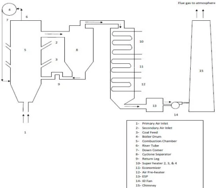
[image:3.612.98.525.318.689.2]CFBC technology the coal particles along with some amount of lime stone particles remains in fluidized form like in fbc technology. Lime stone is added in the combustion zone to reduce pollution. The fluidization takes place due to primary air coming from the windbox which contributes almost 60% in combustion process while the remaining 40% air is supplied from side duct as a secondary air which causes high turbulence in combustion zone. A typical layout of power plant operating on CFBC technology is shown in figure 1.
Technology (IJRASET)
[image:4.612.127.486.181.266.2]Here, primary is coming into combustion chamber by passing through nozzle. The type of nozzle used is an important one because it guides the air and develops different flow pattern. Here in our investigation, different three types of nozzles are considered and flow profiles in terms of velocity is obtained by using ansys fluent tool. The three nozzles are mushroom type, arrow head type and pig tail type nozzle. The nozzle which gives maximum velocity in combustion zone, we can termed as best nozzle among three. Table 1 provides information about typical CFBC boiler parameters in our consideration.
TABLE - 1
PARAMETERS OF CFBC BOILER.
Type Top supported, Natural circulation, Water tube CFBC boiler.
Capacity(TPH) 100
Steam pressure(bar) 105
Steam temperature(oC) 505
Dimension(m) 5.1*4.9*34.8
III. GENERATIONOFMODELANDMESHING
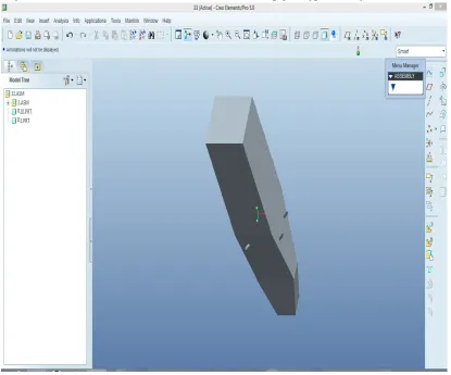
The actual model of combustion chamber of CFBC boiler is very complex as boiler design is a very complicated field. So by taking 1:10 based scale three different model of combustion chamber of CFBC boiler is been developed by using pro e 5.0 software tool for three different nozzle geometry. For mushroom type nozzle the actual number of nozzle is 220 but it is very difficult to simulate such a huge model. So an array of 7*4 is been considered for simplicity purpose. Similar to mushroom type nozzle, for arrow head type nozzle, an array of 7*4 is been considered while for third nozzle which is pig tail type, an array of 6*5 is been developed.
Fig. 2 Three dimensional model of CFBC combustion chamber.
[image:4.612.105.520.336.681.2]Technology (IJRASET)
Meshing is been generated by taking tetrahedral element for all three geometry. The numbers of nodes are 1149015, 106920, and 123929 for mushroom type, arrow head type and for pig tail type nozzle respectively. While numbers of elements are 5867185, 559666 and 61431 for mushroom type, arrow head type and for pig tail type respectively. Figure 3, 4 and 5 shows meshing of CFBC boiler geometry with mushroom type, arrow head type and for pig tail type nozzle respectively.
IV. BOUNDARYCONDITIONS.
[image:5.612.53.579.566.710.2]Boundary conditions are the conditions which puts constraint in analysis. Here in our analysis, air is considered as a working fluid with density 0.815 kg/m3 and dynamic viscosity as 24.32*10-6 at temperature of 160oC. All bottom side of all the nozzles are given.
Fig. 3 Meshing on CFBC boiler combustor model with mushroom type nozzle.
Technology (IJRASET)
as pressure inlet with air pressure 130 mbar and temperature 160oC. All ducts on walls for secondary air inlet is given as pressure inlet with pressure 75 mbar and temperature 160oC. A standard k-€ model has been considered for analysis purposeIn special discretization module, gradient is taken as least square based, pressure is considered as second order and momentum is selected as second order upwind.
V. RESULTSANDDISCUSSION
[image:6.612.115.501.220.436.2]After providing above boundary conditions, the results can be obtained in different forms like velocity profile, pressure profile, turbulent kinetic energy etc. But here our aim is to obtain the type of nozzle which causes maximum velocity. So the velocity profiles have been developed. Figure 6, 7 and 8 provides velocity profiles with mushroom type, arrow head type and pig tail type nozzle grid respectively. From Figure 6, the maximum value of velocity is about 29.1 m/s and also this maximum velocity is generated into a small region of combustion zone. This value belong to mushroom type nozzle grid.
Fig 6. Velocity profile with mushroom type nozzle.
[image:6.612.122.505.463.705.2]Technology (IJRASET)
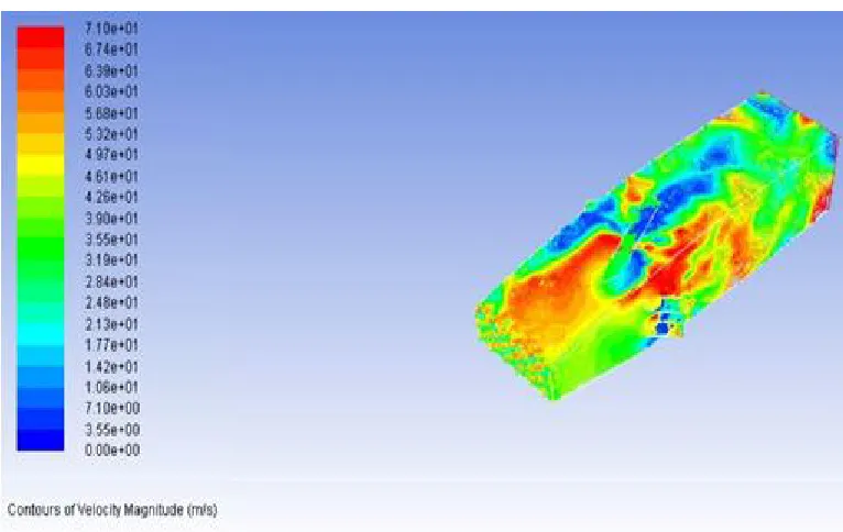
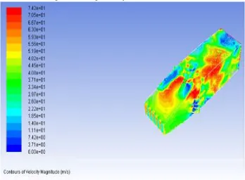
[image:7.612.139.487.140.396.2]As per Figure 7, the magnitude of maximum velocity is about 71 m/s and the region of this high velocity is also better as compared to other two types of nozzles. This value is of arrow head type nozzle grid. The maximum velocity of order 71 m/s is close to CFBC boiler power plant designed value of order 59 m/s. In figure 8, the maximum magnitude of velocity is about 74.2 m/s which is highest among all of three kind of nozzle and belong to pig tail nozzle grid. However, problem with this nozzle array is that, only small region can be obtained which is having this much high velocity.
Fig. 8 Velocity profile with pig tail type nozzle.
From the above discussion, we can say that by using pig tail type nozzle, the maximum air velocity in combustion chamber of CFBC boiler can be achieved. But values of velocity for arrow head type and for pig tail type nozzle are nearer as 71 m/s and 74 m/s respectively. Also more region with this high magnitude of velocity can be achieved with the help of arrow head type nozzle. Mushroom type nozzle, which can give velocity magnitude about only 29 m/s which is poorer as compared to other two nozzle design.
VI. CONCLUSIONANDFUTURESCOPEOFWORK
Here, presented work consist of CFD simulation of combustion chamber of CFBC boiler by taking into account three different kind of nozzle array which are mushroom type nozzle, arrow head type nozzle and pig tail type nozzle. Type of nozzle grid affects primary air distribution in combustion zone as per nozzle geometry. Here three nozzle grids have been modeled with different three kinds of nozzles by using Pro E 5.0 software. According to those different nozzle grids, three velocity profiles have been generated by using ansys fluent tool. Velocity magnitude is 29.1 m/s, 71 m/s and 74.2 m/s have been obtained for mushroom type nozzle, arrow head type nozzle and for pig tail type nozzle grid respectively. The practical value in case of arrow head type nozzle grid installed in CFBC thermal power station is 59 m/s which is nearer to simulated value which is 71 m/s. So, the maximum amount of velocity can be seen in array of pig tail type nozzle. Also if we carefully examine whole body than we can see that maximum area with red zone appears in the case of arrow head type nozzle grid which tells that maximum magnitude of velocity is in wide region as compared to other cases which is preferable because 3.2 m/s velocity difference can be obtained in between pig tail type nozzle and arrow head type nozzle grid.
Technology (IJRASET)
REFERENCES
[1] C. Bhasker, Simulation of air flow in typical boiler wind box segment, Advances in engineering softwares, vol. 33,2002, pp. 793-804.
[2] Masoud Rahimi, Abbas Khoshhal, Seyed Mehdi Shariati, CFD modelling of boiler tube rapture, Applied thermal engineering, vol 26, 2006, pp. 2192-2200. [3] E. J. Anthony, A. P. Iribarne, J. V. Iribarne, Fouling in a utility scale CFBC boiler firing 100% petroleum coke, Fuel processing technology, vol 88, 2007, pp.
535-547.
[4] T. Asotani, T. Yamashita, H. Tominaga, Y. Eusagi, Y. Itaya, S. Mori, Prediction of ignition behaviour in tangentially fired pulverized coal boiler using CFD, Fuel, vol. 87, 2008, pp. 482-490.
[5] Deng Jianxin, Ding Zeliang, Zhou Houming, Tan Yuanqiang, Performance and wear characteristics of ceramic, cemented carbide, and metal nozzle used in coal-water-slurry boiler, Int. journal of refractory metals and hard materials, vol. 27, 2009, pp. 919-926.
[6] Anil Purimetla, Jie Cui, CFD studies on burner secondary air flow, Applied mathematical modelling, vol. 33, 2009, pp. 1126-1140.
[7] Nan Zhang, Bona Lu, Wei Wang, Jinghai Li, 3D CFD simulation of hydrodynamics of a 150MWe circulating fluidized bed boiler, Chemical engineering journal, vol. 162, 2010, pp. 821-828.
[8] Hari Babu Vuthaluru, Rupa Vuthaluru, Control of ash related problems in a large scale tangentially fired boiler using CFD modelling, Applied energy, vol.87, 2010, pp. 1418- 1426.
[9] Pawel Mirek, Designing of primary air nozzles for large scale CFB boilers in a combined numerical experimental approach, Chemical engineering and processing: process intensification, vol. 50, 2011, pp. 694-701.