International Journal of Emerging Technology and Advanced Engineering
Website: www.ijetae.com (ISSN 2250-2459, Volume 2, Issue 7, July 2012)136
FPGA BASED IMPLEMENTATION OF DOUBLE PRECISION
FLOATING POINT ADDER/SUBTRACTOR USING VERILOG
Addanki Purna Ramesh
1, Ch.Pradeep
21,2Department of ECE, Sri Vasavi Engineering College, Pedatadepalli, Tadepalligudem, India.
Abstract - Floating Point operations is widely used in many areas, especially in signal processing. The greater dynamic range and lack of need to scale the numbers makes development of algorithms much easier. However, implementing arithmetic operations for floating point numbers in hardware is very difficult. The IEEE floating point standard defines both single precision (32-bit) and double precision (64-bit) formats. In this paper a double precision floating point adder/subtractor is implemented using Verilog. The code is dumped into vertex-5 FPGA.
Keywords - Floating Point, IEEE, FPGA, double precision, Verilog, Arithmetic unit.
I. INTRODUCTION
The advantage of floating-point representation over fixed-point and integer representation is that it can support a much wider range of values.
For many signal processing, and graphics applications, it is acceptable to trade off some accuracy (in the least significant bit positions) for faster and better implementations. A Floating point describes a method of representing real numbers in a way that can support a wide range of values. . The base for the scaling is normally 2, 10 or 16.
Double precision floating point is an IEEE 754 standard for encoding binary or decimal floating point numbers in 64 bits. The IEEE 754 standard defines a double as 1 bit for sign,11 bits for Exponent,53 bits (52 explicitly stored) for Significand.The Double precision floating point format is shown in figure 1.
1 sign bit 11-bits exponent 52-bits mantissa
Figure 1: Double Precision Floating-Point Format
II. IMPLEMENTATION
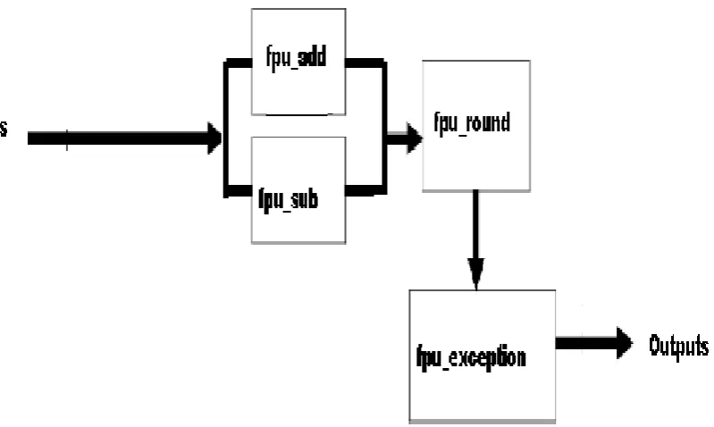
The double precision floating point adder/subtractor performs addition, subtraction operations. The block diagram of double precision floating point adder/subtractor (fpu_double) is shown in figure 2.
It consists of 4 sub blocks. The blocks are 1 Fpu_add
2 Fpu_sub 3 Fpu_round 4 Fpu_exceptions
The Black box view of double precision floating point adder/subtractor is shown in figure 3.
The input signals to the top level module are 1. Clk
2. Rst 3. Enable
4. Rmode (Rounding mode) 5. Fpu_op
6. Opa (64 bits) 7. Opb (64 bits)
Table 1&2 shows the Rounding Modes selected for various bit combinations of rmode and Operations selected for various bit combinations of Fpu_op.
International Journal of Emerging Technology and Advanced Engineering
Website: www.ijetae.com (ISSN 2250-2459, Volume 2, Issue 7, July 2012) [image:2.595.91.491.142.381.2]137
Figure 2: Block diagram of double precision floating point adder/subtractor.
[image:2.595.88.280.432.740.2]Figure:3 Black box view of Double Precision floating point adder/subtractor
Table 1
Rounding Modes selected for various bit combinations of rmode
Bit combination Rounding Mode
00 round_nearest_even 01 round_to_zero
10 round_up
11 round_down
Table 2
Operations selected for various bit combinations of Fpu_op
Bit combination Operation
000 Addition
001 Subtraction
The output signals from the module are the following
1 Out_fp (output from operation, 64 bits) 2 Ready
3 Underflow 4 Overflow 5 Inexact 6 Exception 7 Invalid.
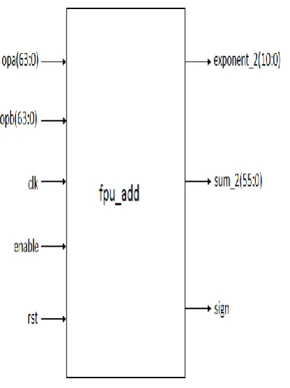
A. Addition
International Journal of Emerging Technology and Advanced Engineering
Website: www.ijetae.com (ISSN 2250-2459, Volume 2, Issue 7, July 2012)138
[image:3.595.332.540.187.478.2]The comparison of the operands to determine which is larger only compares the exponents of the two operands, so in fact, if the exponents are equal, the smaller operand might populate the “mantissa large” and “exponent large” registers. This is not an issue because the reason the operands are compared is to find the operand with the larger exponent, so that the mantissa of the operand with the smaller exponent can be right shifted before performing the addition. If the exponents are equal, the mantissas are added without shifting.
Figure 4: Black box view of Addition Module B. Subtraction
Figure 5 shows the black box view of subtraction module (fpu_sub).The input operands are separated into their mantissa and exponent components, and the larger operand goes into “mantissa large” and “exponent large”, with the smaller operand populating “mantissa small” and “exponent small”. Subtraction is similar to addition in that you need to calculate the difference in the exponents between the two operands, and then shift the mantissa of the smaller exponent to the right before subtracting. The definition of the subtraction operation is to take the number in operand B and subtract it from operand A.
However, to make the operation easier, the smaller number will be subtracted from the larger number, and if A is the smaller number, it will be subtracted from B and then the sign will be inverted of the result.
Figure 5: Black box view of subtraction module C. Rounding
Rounding takes a number regarded as infinitely precise and, if necessary, modifies it to fit in the destination‟s format while signalling the inexact exception, underflow, or overflow when appropriate. Except where stated otherwise, every operation shall be performed as if it first produced an intermediate result correct to infinite precision and with unbounded range, and then rounded that result according to one of the attributes in this clause.
An infinitely precise result with magnitude at least
b emax(b − ½ b 1−p) shall round to ∞ with no change
in sign; here emax and p are determined by the destination format as
[image:3.595.81.289.281.559.2]International Journal of Emerging Technology and Advanced Engineering
Website: www.ijetae.com (ISSN 2250-2459, Volume 2, Issue 7, July 2012)139
Round Ties ToAway, the floating-point number nearest to the infinitely precise result shall be delivered; if the two nearest floating-point numbers bracketing an unrepresentable infinitely precise result are equally near, the one with larger magnitude shall be delivered.
Three other user-selectable rounding-direction attributes are defined, the directed rounding attributes
RoundTowardPositive, the result shall be the format‟s floating-point number (possibly +∞) closest to and no less than the infinitely precise result
RoundTowardNegative, the result shall be the format‟s floating-point number (possibly −∞) closest to and no greater than the infinitely precise result
RoundTowardZero, the result shall be the format‟s
floating-point number closest to and no greater in magnitude than the infinitely precise result.
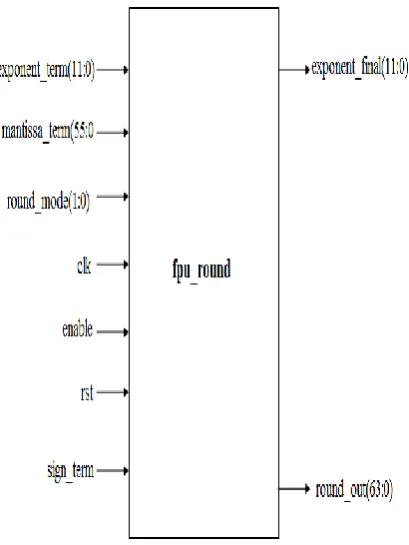
Fpu_round module performs the rounding operation. The black box view is shown in figure 6.
[image:4.595.73.278.380.653.2].3.1.0
Figure 6: Black box view of rounding Module
The inputs to the (fpu_round) module from the previous stage (addition, subtraction, multiply, or divide) are sign (1 bit), mantissa_term (56 bits), and exponent_term (12 bits). The mantissa_term includes an extra „0‟ bit as the MSB, and two extra remainder bits as LSB‟s, and in the middle are the leading „1‟ and 52 mantissa bits.
The exponent term has an extra „0‟ bit as the MSB so that an overflow from the highest exponent (2047) will be caught; if there were only 11 bits in the register, a rollover would result in a value of 0 in the exponent field, and the final result of the fpu operation would be incorrect.
There are 4 possible rounding modes. Round to nearest (code = 00), round to zero (code = 01), round to positive infinity (code = 10), and round to negative infinity (code = 11).
For round to nearest mode, if the first extra remainder bit is a „1‟, and the LSB of the mantissa is a „1‟, then this will trigger rounding. To perform rounding, the mantissa_term is added to the signal (rounding_amount). The signal rounding_amount has a „1‟ in the bit space that lines up with the LSB of the 52-bit mantissa field. This „1‟ in rounding_amount lines up with the 2 bit of the register (mantissa_term); mantissa_term has bits numbered 55 to 0. Bits 1 and 0 of the register (mantissa_term) are the extra remainder bits, and these don‟t appear in the final mantissa that is output from the top level module, fpu_double.
For round to zero modes, no rounding is performed, unless the output is positive or negative infinity. This is due to how each operation is performed. For multiply and divide, the remainder is left off of the mantissa, and so in essence, the operation is already rounding to zero even before the result of the operation is passed to the rounding module. The same occurs with add and subtract, in that any leftover bits that form the remainder are left out of the mantissa. If the output is positive or negative infinity, then in round to zero mode, the final output will be the largest positive or negative number, respectively.
For round to positive infinity mode, the two extra remainder bits are checked, and if there is a „1‟ in both bit, and the sign bit is „0‟, then the rounding amount will be added to the mantissa_term, and this new amount will be the final mantissa. Likewise, for round to negative infinity mode, the two extra remainder bits are checked, and if there is a „1‟ in either bit, and the sign bit is „1‟, then the rounding amount will be added to the mantissa_term, and this new amount will be the final mantissa. The output from the fpu_round module is a 64-bit value in the round_out register. This is passed to the exceptions module.
D. Exceptions
International Journal of Emerging Technology and Advanced Engineering
Website: www.ijetae.com (ISSN 2250-2459, Volume 2, Issue 7, July 2012)140
[image:5.595.83.272.229.501.2]Note that event, exception, and signal are defined in diverse ways in different programming environments. The exceptions module is shown in figure7.All of the special cases are checked for, and if they are found, the appropriate output is created, and the individual output signals of underflow, overflow, inexact, exception, and invalid will be asserted if the conditions for each case exist.
Figure 7: Black box view of Exception Module
The exception signal will be asserted for the following special cases.
1. Divide by 0: Result is infinity, positive or negative, depending on sign of operand A
2. Divide 0 by 0: Result is SNaN, and the invalid signal will be asserted
3. Divide infinity by infinity: Result is SNaN, and the invalid signal will be asserted
4. Divide by infinity: Result is 0, positive or negative, depending on the sign of operand A the underflow signal will be asserted
5. Multiply 0 by infinity: Result is SNaN, and the invalid signal will be asserted
6. Add, subtract, multiply, or divide overflow: Result is infinity, and the overflow signal will be asserted 7. Add, subtract, multiply, or divide underflow: Result
is 0, and the underflow signal will be asserted 8. Add positive infinity with negative infinity: Result
is SNaN, and the invalid signal will be asserted 9. Subtract positive infinity from positive infinity:
Result is SNaN, and the invalid signal will be asserted
10. Subtract negative infinity from negative infinity: Result is SNaN, and the invalid signal will be asserted
11. One or both inputs are QNaN: Output is QNaN 12. One or both inputs are SNaN: Output is QNaN,
and the invalid signal will be asserted
13. If either of the two remainder bits is „1‟: Inexact signal is asserted.
If the output is positive infinity, and the rounding mode is round to zero or round to negative infinity, then the output will be rounded down to the largest positive number (exponent = 2046 and mantissa is all 1‟s). Likewise, if the output is negative infinity, and the rounding mode is round to zero or round to positive infinity, then the output will be rounded down to the largest negative number. The rounding of infinity occurs in the exceptions module, not in the rounding module. QNaN is defined as Quiet Not a Number. SNaN is defined as Signaling Not a Number. If either input is a SNaN, then the operation is invalid. The output in that case will be a QNaN. For all other invalid operations, the output will be a SNaN. If either input is a QNaN, the operation will not be performed, and the output will be a QNaN. The output in that case will be the same QNaN as the input QNaN. If both inputs are QNaNs, the output will be the QNaN in operand A.
III. SIMULATION RESULTS
International Journal of Emerging Technology and Advanced Engineering
Website: www.ijetae.com (ISSN 2250-2459, Volume 2, Issue 7, July 2012)141
Figure 8: Simulation Results for Floating point addition
Figure 9: Simulation Results for Floating point subtraction
IV. CONCLUSION
This paper presents the implementation of double precision floating point adder/subtractor (addition, subtraction). The whole design was captured in Verilog Hardware description language (HDL), tested in simulation using Model Tech‟s modelsim, placed and routed on a Vertex 5 FPGA from Xilinx. The proposed VLSI implementation of the Double Precision adder/subtractor increases the precision over the Single Precision arithmetic unit.
REFERENCES
[1 ] J. D. Bruguera and T. Lang. Leading-one prediction withconcurrent position correction. IEEE Transactions on Computers,48(10):1083.1097, Oct 1999.
[2 ] M. F. Cowlishaw. Decimal arithmetic FAQ: Part 1 – general questions.
http://www2.hursley.ibm.com/decimal/decifaq1.htm, 2003. [3 ] A. Y. Duale, M. H. Decker, H.-G. Zipperer, M. Aharoni, and
International Journal of Emerging Technology and Advanced Engineering
Website: www.ijetae.com (ISSN 2250-2459, Volume 2, Issue 7, July 2012)142
[4 ] L. Eisen, J.W.Ward III, H.-W. Tast, N. Mading, J. Leenstra,S. M. Mueller, C. Jacobi, J. Preiss, E. M. Schwarz, and S. R. Carlough. IBM POWER6 accelerators: VMX and DFU. IBM Journal of Research and Development, 51(6):663.684, 2007. [5 ] W. Haller, U. Krauch, T. Ludwig, and H. Wetter. Combined
binary/decimal adder unit. U.S. Patent 5,928,319, July 1999. [6 ] E. Hokenek and R. K. Montoye. Leading-zero anticipator
(LZA) in the IBM RISC System/6000 _oating-point execution unit. IBM Journal of Research and Development, 34(1):71.77, 1990.
[7 ] IBM. General decimal arithmetic testcases. http://speleotrove.com/decimal/dectest.html.
[8 ] IBM Corporation. The decNumber library. http://www2.hursley.ibm.com/decimal/decnumber.pdf, April 2008.
[9 ] IEEE Inc. IEEE 754-2008 Standard for Floating-Point Arithmetic. New York, 2008. Intel Corp. Intel decimal _oating-point math
library.http://softwarecommunity.intel.com/articles/eng/3687.h tm.
[10 ]D. E. Knuth. Fundamental Algorithms, volume 1 of TheArt of Computer Programming, section 1.2, pages 10.119.
Addison-Wesley, Reading, Massachusetts, second edition,10 Jan. 1973.
[11 ]Microsoft Corporation. C# language speci_cation.http://msdn.microsoft.com/library/
default.asp?url=/library/en-us/csspec% /html/CSharpSpecStart.asp, 2002.
[12 ]H. Nikmehr, B. Phillips, and C. C. Lim. A decimal carryfree adder. In Proceedings of the SPIE Symposium on Smart Materials, Nano-, and Micro-Smart Systems, volume 5649, pages 786.797, February 28 2005.
[13 ]V. G. Oklobdzija. An algorithmic and novel design of a leading zero detector circuit: Comparison with logic synthesis. IEEE Transactions on Very Large Scale Integration (VLSI) Systems, 2:124 . 128, March 1994.
[14 ]M. S. Schmookler and D. G. M. Jr. Two state leading zero/one anticipator (LZA). U.S. Patent #5,493,520, Feb 1996. [15 ]M. S. Schmookler and A. W. Weinberger. High speed decimal
addition. IEEE Transactions on Computers, C-20:862. 867, Aug 1971.
[16 ]E. M. Schwarz, J. Kapernick, and M. Cowlishaw. Decimal _oating-point support on the IBM z10 processor. IBM Journal of Research and Development, 53(1), 2009.
[17 ]Sun Microsystem. BigDecimal Class, Java Platform 1.1 API Speci_cation. http://java.sun.com/products/
archive/jdk/1.1/, 1999.