Intelligent Custom Block Generation
Michael F. Dossis
Department of Informatics Engineering, Technological Educational Institute of Western Macedonia, Kastoria Campus, Kastoria, 52 100, Greece
*Corresponding Author: [email protected]
Copyright © 2014 Horizon Research Publishing All rights reserved.
Abstract
The current density of integration circuits, yields extremely complex Systems-on-a-Chip (SoCs) that take a long time to design and develop and thus, many times, they miss the market window for these products. This has motivated intensive research on High-level Synthesis (HLS) methodologies, so that such complex and custom systems are rapidly designed and prototyped. The contribution of this work is a formal and intelligent HLS synthesis and rapid verification methodology with custom options, which re-uses and incorporates the generation of predesigned custom hardware functional units, from abstract behavioural ADA code. The usability of the proposed methodology is confirmed with a number of HLS benchmarks including a hierarchical RSA crypto-processor design and a line-drawing algorithm from computer graphics.Keywords
Custom Hardware Synthesis/Compilation, High-level Synthesis, Hardware Verification, Design Automation, Formal Methods, Intelligent Systems1. Introduction
The recent explosion in the density of Integrated Circuits (IC), has caused an amazing proliferation of competitive integrated products in ever reducing lifetime in the market. Such circuits are found in complex systems, such as embedded, and portable and consumer electronics. These systems consist of very complex components, such as heterogeneous processor cores, custom processing units, (distributed or shared) memories, design hierarchy, buses, external interface modules and interconnections. Therefore formal High-Level Synthesis (HLS) methodologies are needed, in order to handle this design complexity, achieve higher specification abstraction, development flow automation, quality of implementations and rapid specification-to-product times. In this way, enterprises and research organizations will become more competitive and will manage to support customer requirements and short market windows.
International efforts in HLS, in both industry and academia have made possible to produce significant E-CAD,
Electronic System Level design tools that use HLS transformations to automatically deliver custom hardware logic. Nevertheless, HLS tools are still not widely adopted by the engineering community. This is primarily due to incompatibilities of their input formats and their poor results when they are used for large systems with complex module and control-flow hierarchy. This prevents the wide use of these tools for delivering custom functions and custom hardware blocks. In addition, the majority of the existing tools impose proprietary extensions or restrictions on the input programming code set, and they apply suboptimal heuristics on their optimizing transformations. These make them suitable only for linear, dataflow dominated systems, such as image processing and streaming applications.
The main contribution of this work is the capability to automatically and formally generate complex circuits that instantiate custom hardware blocks, using the formal CCC (Custom Coprocessor Compilation) behavioural HLS synthesizer [1]. The CCC hardware compilation framework is based on compiler-compilers and formal logic relations, therefore the generated hardware implementation is provably-correct and by definition, it matches the functionality of the input specification model. The formal nature of the hardware compilation transformations eliminates the need for time-consuming RTL and annotated gate netlist simulations. The proposed HLS design framework 1 incorporates an aggressive, resource-constrained scheduler so that it achieves the maximum operation parallelism [2] into as few as possible hardware sequential states. The source ADA code is transformed into the Intermediate Tables Format (ITF) 2 [3], iiiiiiusing compiler-compiler techniques [4], and ITF is optimally transformed into functionally equivalent hardware using the PARCS (Parallel, Abstract Resource – Constrained Scheduler) optimizer, using logic relations [5], logic predicates and inference logic [6]. All these features are integrated into the CCC toolset and methodology and are making possible to automatically generate custom functions and extremely complex custom designs in hardware that can be used to accelerate the host computing system. That is why
1 The CCC ESL hardware compiler method is patented with patent number: 1005308, 5/10/2006, from the Greek Industrial Property Organization (OBI) 2 The intermediate tables format is patented with patent number: 1006354, 15/4/2009, from the Greek Industrial Property Organization
this work is so important and contributes towards the international research on HLS status. Moreover, the current research work is not just theoretical but has been proven with real-world applications that were verified in both the abstract, high-level ADA code and the generated RTL VHDL/Verilog code. All these formats are widely used in every-day industrial practices which enhance the usability of the presented E-CAD tools.
The main importance of this work is the formal nature of the transformations that are employed in the developed HLS framework. This alleviates the problem and need of re-verifying the automatically generated RTL hardware implementation. The designer can rely on the formal nature of the CCC synthesizer so as to avoid lengthy RTL or even more, gate-netlist simulations and verification is contained only at the abstract compile-and-execute method of the coded ADA programs. This is why this work is so important to be supported with funding and industrial practice, since its adoption can reduce the time-to-market and spec.-to-product cycles by orders of magnitude, and thus allow the system designers to concentrate on the most important, architectural issues of their systems.
The next section discusses existing work and background on HLS. Section 3 details the custom options of the author’s prototype hardware compiler. Section 4 is a case study of a custom processor synthesis using custom blocks, beginning with the ADA specification of a cryptographic RSA design. Modeling and simulation verification in the CCC design flow are discussed in Section 5. Section 6 outlines synthesis results from a number of selected benchmarks. The last section draws conclusions and suggests future work tasks for the presented HLS framework and design methodology.
2. Existing Methods and Background
The method in [7] maps C programs with pointers and the functions malloc and free, onto hardware implementations that instantiate custom hardware memory allocators. Every allocator is associated with specific memory architectures and the SpC tool [7] translates C functions with complex data structures into equivalent Verilog models. SpC is developed within the SUIF compiler environment [8], and the given memory locations are mapped onto variables and arrays in the Verilog modules, which are in turn compiled into hardware circuits using the Synopsys’s Behavioral Compiler.
A scheduling heuristic on an intermediate design representation that supports chaining and multi-cycling, conditional resource sharing and speculative execution, processes dense control flows in the input specification in [9]. The intermediate format is called hierarchical conditional dependency graph (HCDG).
Coarse-grain and fine-grain parallelizing transformations are executed on input code in [10], both during a pre-synthesis phase and during scheduling. The SPARK HLS tool accepts small subset of C and using these heuristics
transforms it into RTL VHDL implementations [10]. However, there cannot be any design hierarchy (e.g. subroutines) on the accepted C language subset, and of “while” type of loops is not allowed. In order to evaluate SPARK, the MPEG-1, MPEG-2 and GIMP image processing algorithm benchmarks are experimented with [10].
Concurrent loop optimization and multi-cycling are applied on the designs via resource constraints in [11]. This method, runs simultaneously scheduling, resource allocation, module binding, module selection, register binding and clock selection, to improve design energy, power and area.
The incremental floor-planner in [12] combines incremental (high-level) behavioural and physical optimizations, integrated into the interconnect-aware ISCALP tool [13].
The methodology in [14] applies behavioral profiling on the input C behavior, it is implemented into the Cyber tool [15] and it delivers distributed logic and memory architectures. The tool extracts simulation statistics of computations and references of array data, and generates footprints which contain the accessed array locations and the frequency of their occurrence.
In [16] operation scheduling is considered globally, using the system critical path, as opposed to conventional HLS that synthesizes each concurrent process separately (with the individual process critical path). The intended application is specified in [16] using communicating processes.
[17] presents memory access management that targets digital signal processing (DSP) and streaming systems, with specific performance constraints. The optimizations in [17] are executed on the extended data-flow graph (EDFG) which is based on the signal flow graph. EDFG models the access and data computations, the transfers of data, and the condition statements for addressing, computation and data transfers respectively. Mutually exclusive scheduling is run on the EDFG [18], [19]. In [17] address computation balancing is used to move dynamic address computations from the data path unit onto the sequencer, according to a set of criteria. In this way, the overall system performance and design graph are improved and subsequently, the GAUT HLS tool [20] is used to execute operator selection/allocation, scheduling and binding.
More HLS approaches are reported in the bibliography, but they fall in one or more of the above categories. Moreover, the focus of this work is on the formal HLS compiler, developed by the author of this paper that incorporates custom hardware blocks. The uniqueness of this work is the formal nature of the synthesizer, the flexibility of including this method in any existing industrial design flows, and the processing of custom hardware blocks that are available via the CCC methodology.
The CCC HLS design flow is based on the frontend and the backend compilers, both developed using formal methods, including compiler-compilers and logic programming predicate relations. The formal ITF format [13] captures all the algorithmic, data and operator typing, as well the hierarchical information of the input ADA programs, in a formal manner, which is readable both by humans and by the backend compiler, and it is the link between the frontend and the backend compiler. ITF includes a number of tables with homogeneous logic predicate facts [5]. These facts are in turn loaded into the backend inference engine, which produces “formal conclusions” via a number of optimizing transformations, including the generation of the targeted HDL (VHDL and Verilog) RTL models. A functionally-equivalent custom processor is generated from every subroutine of the ADA source code. The generated hardware coprocessors are modeled in RTL code which is independent from any particular silicon technology and backend flow. Every generated hardware RTL module incorporates the FSM and the custom datapath module, that implement in an optimal manner the control and data flow operations of the input programs, respectively.
The CCC framework allows a number of custom options to be selected by the user. These options affect the microarchitecture of the custom processors that are automatically generated from the input specification models (ADA code). In general large data objects such as multidimensional arrays can be located either on chip as distributed registers inside the custom processor, or on chip, on board, or on the system’s main (shared) memory. If location on external (to the coprocessor) memories is selected, then a file of memory communication options must be constructed by the designer. These options file is loaded onto the backend compiler to configure the translation flow accordingly. In this case, all the necessary memory ports, and communication protocols are automatically generated by the CCC tool and are embedded into the total operation schedule of the generated hardware coprocessor. Thus, improved, integrated custom processing optimizations are performed, as opposed to separate and suboptimal core and interface implementations. If on-chip registers are chosen to accommodate the complex data objects, then better performance is achieved, but with a penalty of increased hardware size.
More user custom options are available about the resource constraints that are used to guide the incorporated PARCS scheduler [1]. PARCS is an aggressive parallelizing scheduler that reduces the length of the initial state schedule (the one that comes out directly from the automatic analysis of the ADA programs, plus the custom memory option operations, if any). In order to achieve this PARCS parallelizes the operations into states, while obeying to data and control dependencies that the source program might feature. PARCS will always attempt to use as many operators-functional units in parallel as possible, into the same control state. However, if resource constraints are provided, either as global operator constraints at the
command-line, or those constraints that are associated with a particular hierarchy module using a constraint file, then PARCS will obey the resource constraints. For example, a global constraint of 4 adders can be specified, in which case PARCS will terminate parallelizing as many as 4 parallel adders into the same FSM control step for all modules in the specification code. Alternatively, there can be 5 ADA subprograms that contain addition operations, and if each subprogram is individually constrained with 4, 3, 6, 6, and 8 maximum parallel adders (local constraints, provided in a constraints file) for each subroutine respectively, then PARCS will obey these constraints for each of these subprograms.
Every subprogram in the source code will be optimized into s standalone custom processor that executes the functions of the input subprogram. Moreover, a mix of global and local resource constraints can be applied, in a combination of a command-line option (for all operators) and a constraint file respectively. Then, the minimum constraint value will be applied on PARCS transformations for each module case. The user of the CCC framework, can exploit the resource constraints as a way to rapidly draw cost/efficiency trade-offs, and therefore, to quickly arrive at optimal decisions about the intended type of the system implementation.
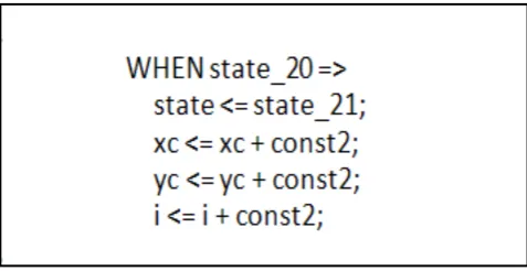
[image:3.595.312.551.455.578.2]Another command-line option determines the type of the generated micro-architecture. By default, the backend compiler generates massively-parallel implementations. With this choice the parallelized operations will be embedded into the state definitions of the state machine (FSM), as shown in the example of Fig. 1.
Figure 1. Massively-parallel solution for the FSM state_20 operations
The benefit of the massively-parallel option is that simple state command wires and fast execution of the operations are implemented without complex data multiplexers with higher area/delay, thus higher clock speed is achieved. The side-effect of this choice is resource redundancy since the operators and functional units, scheduled into inactive states, will be idle for a duration associated with non-relevant control states, and until the respective state is active again.
operators, in the implemented datapath signal assignments.
Figure 2. FSM+datapath implementation of 3 operations FSM state
The FSM+datapath choice delivers more economic implementations since operators are shared between different states, the resource redundancy is kept low, but maybe (depending on the implementation technology) longer clock periods are imposed. The architecture command-line option is another way to quickly arrive at cost/efficiency trade-offs and adapts the design to different technologies such as large ASICs or small (and more economic) FPGAs.
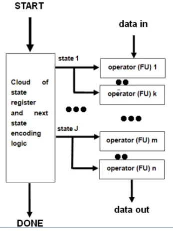
[image:4.595.342.525.190.440.2]The massively-parallel microarchitecture choice is shown graphically in Fig. 3, with the data input and output and the synchronization done and start I/Os. The traditional FSM+datapath choice is depicted in Fig. 4, with the data routing multiplexers explicitly drawn and controlled by long state vectors. In both cases, the functions of the datapath are directly controlled by the FSM states and the conditional transitions.
Figure 3. The massively-parallel option
It is worthy to emphasize that either single chip, or multiple chip implementations can be easily generated using the CCC framework methodology. The generated
FSM co-processors can be mapped onto standalone, separate FPGA/ASICs. Alternatively all, or a number of the generated modules, along with local shared memories can be located on a single chip ASIC or large FPGA. Therefore, the targeted platform and system configuration is flexibly chosen throughout the proposed CCC methodology. Moreover, the generated HDL modules are accepted by, and are compatible with all backend commercial or academic RTL synthesis technologies and all E-CAD vendors.
Figure 4. The FSM+datapath implementation architecture
At the time of editing this paper, two different hardware description languages (HDL) can be chosen by another command-line option. If no specific language is specified, VHDL is chosen by default, which generates fully-synthesizable VHDL RTL code that models the optimized implementation. Moreover, Verilog HDL can be specified, which will generate fully-synthesizable Verilog RTL modules. The generated VHDL or Verilog code is 100% technology-independent and tool vendor independent. Thus, the generated custom processor models can be synthesized with any academic or commercial RTL synthesizer, into any silicon, ASIC or FPGA technology. These features were tested and verified with a large number of benchmark applications that were designed and synthesized with the CCC methodology and tool flow.
[image:4.595.88.262.465.699.2]processor). When the co-processor completes its function, it asserts the DONE output. The handshake event concludes with the indicator RESULTS_READ, asserted by the host environment to indicate the delivering of the result data to the host environment (e.g. the main system processor).
The input ADA code hierarchies as well as the control flow structures are maintained in the optimized HDL modules, in a one-to-one correspondence. The effect of this is that every separate ADA subprogram is translated into a separate, standalone custom co-processor in the RTL code. Also subroutine calls are mapped onto synchronous hand-shake interface events between the controlling co-processor and the controlled co-processor.
By default, the calling and the called module are standalone and they can be synthesized into hardware standalone. However, when simulation is used to verify the functionality of the generated HDL code, both modules need to be instantiated into the verification test bench. Some ADA subroutines may describe custom hardware arithmetic blocks, using Boolean logic, or other pre-verified and tested functional units, that the designer doesn’t want to be modified by the CCC scheduler. Such custom subroutines are directly translated into custom HDL routines and synthesized into the target technology using RTL synthesizers. These subroutines are in turn called as they are, within the state description logic of the custom processor FSM. The custom subroutines must be marked as such in a
custom block options file which is read by the backend compiler, in order to apply “custom block” status to certain defined ADA modules (subprograms). This is explained in more detail in the following section, on a “driven-by-example” basis.
4. Hierarchical Custom Blocks in the
RSA benchmark
An example of using custom options and custom blocks is explained here with a hierarchical set of subroutines that constitute the RSA public-key cryptography processor code, with hierarchy as depicted in Fig. 5.
In Fig. 5, the blue arrows denote hierarchical relations between two subroutines, by means of function call relationships. For example subroutine
INT_TO_BIT_VECTOR is called by subroutine Modular multiplication as well as by Modular exponentiation. The top-level routine (hierarchically) in Fig. 5 is Modular exponentiation. If the CCC synthesizer is executed with no custom options, one standalone VHDL custom co-processor will be generated from each of Fig. 5 subroutines. However, since in the engineering practice, subroutines
BOOTH_FUNCTION, SIMPLE_MOD, and
[image:5.595.343.522.83.272.2]INT_TO_BIT_VECTOR are regarded as Boolean hardware arithmetic logic blocks, they are marked as custom blocks in a custom blocks file. This file has a very simple syntax and it is normally built and provided to the CCC backend compiler by the user of the CCC design methodology.
Figure 5. ADA code hierarchy of the RSA processor
The contents of the custom blocks file can be as in the following listing:
combo(1,"int_to_bit_vector", 1) combo(2,"simple_mod", 1) combo(3,"booth_function", 1)
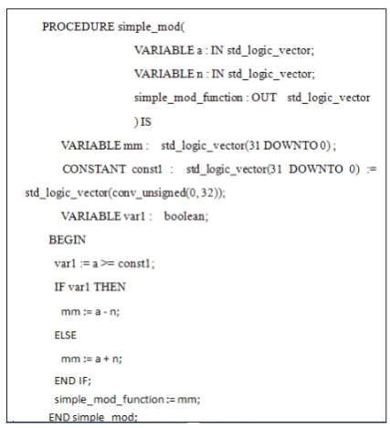
This custom options file marks the respective subroutines as custom hardware blocks, and they will be treated as such throughout the CCC compilation. Therefore, using these options, the CCC compiler will generate for example the VHDL subroutine which is shown in Fig. 6:
Figure 6. VHDL custom block for use in the modular multiplier
[image:5.595.324.538.410.645.2]are captured in the ADA source code subroutines.
Figure 7. Function call of the custom block inside the VHDL FSM
5.
Modeling, Verification and
Simulations in the CCC Design flow
All standard programming language constructs are used in modeling the benchmark test applications in ADA, such as all complex expressions, subroutines, code hierarchy and complex control flow with if-then-else, for-loops, while-loops, case-structures, nested conditionals, loops, records, arrays, etc.
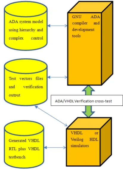
All the applications coded in ADA, were cross-verified with testbench execution between the GNU-ADA level and the VHDL/Verilog simulation level. In all cases the functionality of the automatically generated RTL matched that of the abstract ADA code, which was expected due to the formal nature of the CCC tools. Fig. 8 depicts the CCC cross-verification flow. All tests were rapidly verified using rapid ADA compile-and-execute in the GNU ADA development tools and compiler. The generated VHDL/Verilog is simulated with any standard RTL HDL simulator.
RTL simulations were run only for typical verification flow reasons, and they are not actually needed, since the formality of the CCC tools guarantees the functional correctness of the generated RTL code. In this way, the CCC users need to run verification only at the ADA compile-and-execute level, which is extremely faster than event-driven RTL VHDL/Verilog simulations.
Experience and practice has proved that high-level ADA program verification is orders-of-magnitude faster than typical VHDL/Verilog RTL/gate-netlist simulations. Due to
the formal nature of the CCC synthesizer, there is no requirement for simulation of the provably-correct generated RTL code. RTL simulations were run on all the benchmarks to prove the principle of the argument. VHDL simulation results were loaded back on the ADA testbench for automatic comparison, and all tests matched the functionality of the ADA code.
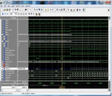
[image:6.595.71.282.93.228.2]Fig. 9 shows a snapshot of the RTL simulation of a line-drawing algorithm that was coded and verified in ADA using the CCC synthesizer. Fig. 9 includes the memory read/write events, and it demonstrates the memory read/writes of the automatically generated memory protocols that were embedded in the optimized custom processor, from custom memory options, dictated for the complex data objects to be placed on external shared memory, which was provided by the designer. This simulation includes the assertion of the DONE signal, indicating the end of co-processor function. Fig. 10 shows a zoomed-in version of the above simulation near the completion of the co-processor function.
[image:6.595.330.537.327.613.2]Figure 9. Simulation of a generated line-drawing processor showing the memory read/writes
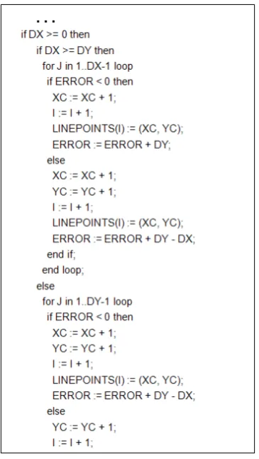
[image:7.595.89.527.356.733.2]Another ADA application code is shown in Fig. 11. This is the main ADA core for a line-drawing algorithm application from computer graphics. 4 levels of nested control constructs are observed in Fig. 11, and they include both for and if then types of control flow structures. This demonstrates the usability of the presented hardware synthesis framework, particularly when processing applications with complex control flow in the source code.
Figure 11. The ADA code segment for the computer graphics algorithm
6. Experimental Tests and Methods
This section discusses experiments using the CCC synthesizer on four benchmarks from the area of high-level hardware synthesis, in order to evaluate the proposed methodology. The CCC compilations were executed on a Pentium-4 PC using the MS-Windows-XP-SP2 operating system. The used CCC synthesis flow is shown in Fig. 12.
These four design benchmarks include a DSP FIR filter, a RSA crypto-processor from the public-key cryptography area, a synthetic benchmark using two level nested for-loops, and a large MPEG video compression algorithm. The third benchmark captures subroutines with two-dimensional data arrays stored on external memories, with read/writes found within the bodies of 2-level nested loops. Fig. 13 shows graphically the state reduction by the PARCS optimizer from the initial schedule to the optimized one. The state reduction rate reaches up to 40% for the
[image:8.595.318.533.193.540.2]MPEG algorithm, and this was done rapidly, by utilising the automatic generation of optimized RTL output. It has been observed that the number of states increases significantly for complex applications such as the MPEG engine, reaching up to 350 control states. It is well known in the engineering community that manual optimization and verification of such high-numbers of control steps (states) are practically impossible to be completed on time for the right market window.
[image:8.595.352.514.199.378.2]Figure 12. Experimental CCC synthesis flow
Figure 13. State reduction from the initial schedule to the PARCS
schedule
Table 1 contains the number of states and the state reduction rates of the four benchmark subroutines. This enforces the author’s argument about compiling real application code with complex constructs and hierarchy. Impressive optimizations up to 41% are achieved by the PARCS scheduler in the case of the FIR filter. The 2nd subroutine of the nested loops benchmark, was processed for both embedded registers and external memory options. The state reduction rate is higher for the embedded (on-chip) memory choice than the external memory. This is because the 2nd choice of the necessary communication protocols,
even with the shared memories, state reduction of 26% was achieved. All of the generated FSMs and data paths were simulated at the RTL VHDL/Verilog level, and the results
[image:9.595.88.520.129.369.2]of the simulations match with that of the ADA program executions.
Table 1. ADA benchmarks with state reduction rates
Module Name Initial Schedule States Optimized (PARCS) States Reduction State Rate FIR filter main routine 17 10 41% Differential equation solver 20 13 35% RSA main routine 16 11 31% nested loops 1st routine 28 20 29% nested loops 2nd routine (with embedded memory) 36 26 28% nested loops 2nd routine (with external memory) 96 79 18% nested loops 3rd routine 15 10 33% nested loops 4th routine 18 12 33% nested loops 5th routine 17 13 24% MPEG 1st routine 88 56 36% MPEG 2nd routine 88 56 36% MPEG 3rd routine 37 25 32% MPEG top routine (with embedded memory) 326 223 32% MPEG top routine (with external memory) 462 343 26%
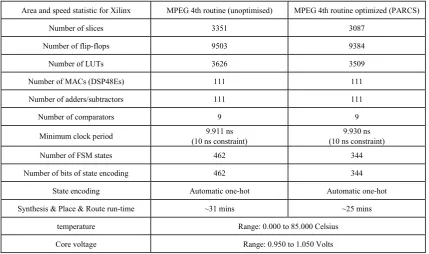
In order to prove and test the synthesizability argument of this paper, the Xilinx XST and Synopsys DC Ultra RTL synthesizers were both used to synthesize all of the generated RTL modules from the four (and not only) benchmarks. The fourth (top-level) routine of the MPEG benchmark Xilinx Synthesis and Place & Route run, as well as the Synopsys RTL synthesis run statistics are detailed in Table 2 and Table 3. The XST and technology place and route ran using the Xilinx Design Suite 10.1 and the design was mapped on Xilinx Virtex5 XC5VLX330T, package FF1738, speed -2 device. The Synopsys RTL synthesis and technology mapping ran from within the DC-ULTRA version C-2009.06-SP3 and was mapped on TSMC 1.3 um technology libraries. The implementation details for this are shown in Table 3.
Table 2. XILINX VIRTEX-5 Implementation Statistics for the MPEG Benchmark
Area and speed statistic for Xilinx MPEG 4th routine (unoptimised) MPEG 4th routine optimized (PARCS) Number of slices 3351 3087
Number of flip-flops 9503 9384 Number of LUTs 3626 3509 Number of MACs (DSP48Es) 111 111 Number of adders/subtractors 111 111 Number of comparators 9 9 Minimum clock period (10 ns constraint) 9.911 ns (10 ns constraint) 9.930 ns Number of FSM states 462 344 Number of bits of state encoding 462 344
State encoding Automatic one-hot Automatic one-hot Synthesis & Place & Route run-time ~31 mins ~25 mins
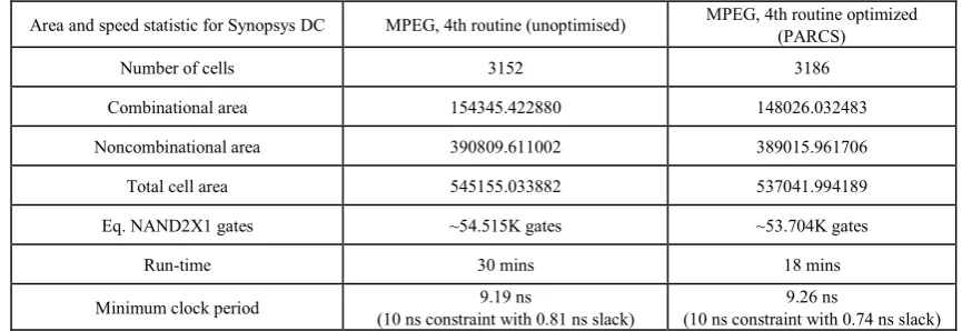
[image:9.595.91.521.481.735.2]Table 3. Synopsys DC-Ultra with TSMC libraries result
Area and speed statistic for Synopsys DC MPEG, 4th routine (unoptimised) MPEG, 4th routine optimized (PARCS) Number of cells 3152 3186
Combinational area 154345.422880 148026.032483 Noncombinational area 390809.611002 389015.961706 Total cell area 545155.033882 537041.994189 Eq. NAND2X1 gates ~54.515K gates ~53.704K gates
Run-time 30 mins 18 mins
Minimum clock period (10 ns constraint with 0.81 ns slack) 9.19 ns (10 ns constraint with 0.74 ns slack) 9.26 ns
Both Xilinx and Synopsys statistics apply to implementations that were compiled with the default massively-parallel architecture choice. Thus, even more economic (in terms of hardware area and used resources) numbers can be achieved using the conventional FSM+datapath micro-architecture choice.
It is remarkable that the occupied area and resource figures of the optimized schedule are not so much higher than the initial schedule. This is due to the optimum nature and connectivity features of the generated RTL coding style and architecture of the used prototype design toolset.
7. Discussion on the Custom Blocks
Custom blocks are very useful in hardware/system design. Custom blocks model custom hardware arithmetic units, such as floating-point units, trigonometric functions, pixel processing primitives, DSP accumulators and routines, cryptographic elementary operations, redundant arithmetic logic blocks, etc. These blocks are usually pre-designed and pre-verified at the module level, or they are found in parallel system cell instantiations such as massively-parallel arrays. Usually, the designers want to use such custom units as they are, without optimizations and modifications imposed by synthesis. This capability and flexibility is enabled by the CCC framework and it is one of the main contributions of the presented work. At the moment custom blocks can be utilized only in the VHDL flow, but on-going work exists to allow the Verilog option as well.
Custom blocks can be hierarchical such as the example of Fig. 5. This means that in both the source ADA and the generated VHDL routine level, there can be custom subroutine calls to each other without any constraints. For example, modular multiplication can be marked as custom block as well, and this will command the CCC compiler to generate a set of hierarchical custom VHDL functions with one of them (the equivalent to modular multiplication) calling the other three modules. These functions will be implemented as basic combinatorial hardware arithmetic
functions and they will be executed both in synthesis and verification flows as they are defined in the VHDL procedure system. The top-level function block modular multiplication will be eventually instantiated whenever it is invoked in the FSM states as a procedure call. All the benchmarks of this work were also tested with their bottom subroutines implemented as custom blocks, and their verification, using this custom option exhibited no functional problems whatsoever.
8. Conclusions and Future Work
The main contribution of this work is the formal synthesis of custom co-processors from executable specifications in ADA programs, using custom options, such as memory system configuration, use of custom blocks, targeted HDL language, and target micro-architecture. The presented design flow allows for rapid, formal and easy to get acquainted with, modeling, verification and simulations, even for not very experienced users.
A great number of tests were synthesized and verified using the presented methods, and all of them proved the high quality, speed and usability of the evaluated CCC development flow. Four of these benchmarks are analyzed, executed and discussed in this work. The generated co-processor models are seamlessly synthesized with any RTL synthesizer, simulated with any HDL simulator and they are mapped to any of the available FPGA or ASIC technologies.
Acknowledgements
This work was partially supported by the TEI of Western Macedonia, Greece.
REFERENCES
[1] M.F. Dossis, “A Formal Design Framework to Generate Coprocessors with Implementation Options”, International Journal of Research and Reviews in Computer Science (IJRRCS), ISSN: 2079-2557, Science Academy Publisher, United Kingdom, www.sciacademypublisher.com, Vol 2, No 4, 2011, pp. 929-936.
[2] P.G. Paulin, and J.P. Knight, “Force-directed scheduling for the behavioral synthesis of ASICs”, IEEE Trans Comput-Aided Des Integ Circuits Syst, Vol 8, No 6, 1989, pp. 661–679.
[3] Michael Dossis, "Intermediate Predicate Format for Design Automation Tools", Journal of Next Generation Information Technology (JNIT), vol. 1, no. 1, 2010, pp. 100-117.
[4] A. Holub, Compiler Design in C, Prentice-Hall Inc., Englewood Cliffs, New Jersey, USA, 1990.
[5] U. Nilsson, U., and J. Maluszynski, Logic Programming and Prolog, John Wiley & Sons Ltd., 2nd Edition, 2000.
[6] R.A. Walker, and S. Chaudhuri, S., “Introduction to the scheduling problem”, IEEE Des & Test of Comput, Vol. 12, No 2, 1995, pp. 60–69.
[7] L. Semeria, K. Sato, and G. De Micheli, “Synthesis of hardware models in C with pointers and complex data structures”, IEEE Trans VLSI Systems, Vol. 9, No 6, 2001, pp. 743–756.
[8] R.P. Wilson, et al, “Suif: An infrastructure for research on parallelizing and optimizing compilers”, ACM SIPLAN Notices, Vol. 28, No. 9, 1994, pp. 67–70.
[9] A. Kountouris, and C. Wolinski, “Efficient Scheduling of Conditional Behaviors for High-Level Synthesis”, ACM Trans. on Design Aut of Electr Sys, Vol. 7, No. 3, 2002, pp. 380–412.
[10] S. Gupta, R.K. Gupta, N.D. Dutt, and A. Nikolau, “Coordinated Parallelizing Compiler Optimizations and High-Level Synthesis”, ACM Trans on Des Aut of Electr Sys, Vol. 9, No. 4, 2004, pp. 441–470.
[11] W. Wang, T.K. Tan, et al, “A comprehensive high-level synthesis system for control-flow intensive behaviors”, Proceedings of the 13th ACM Great Lakes symposium on VLSI GLSVLSI '03, 2003, pp. 11-14.
[12] Z.P. Gu, J. Wang, R.P. Dick, and H. Zhou, “Incremental exploration of the combined physical and behavioral design space”, Proceedings of the 42nd annual conference on Design Automation DAC '05, 2005, pp. 208-213.
[13] L. Zhong, N.K. Jha, “Interconnect-aware high-level synthesis for low power”, Proceedings of the IEEE/ACM International Conference on Computer-Aided Design, 2002, pp. 110-117. [14] C. Huang, S. Ravi, A. Raghunathan, and N.K. Jha,
“Generation of Heterogeneous Distributed Architectures for Memory-Intensive Applications Through High-Level Synthesis”, IEEE Trans on Very Large Scale Integr (VLSI) Sys, Vol. 15, No. 11, 2007, pp. 1191-1204.
[15] K. Wakabayashi, “C-based synthesis experiences with a behavior synthesizer, Cyber”, Proceedings of the Design Automation and Test in Europe Conference, 1999, pp. 390–393.
[16] W. Wang, A. Raghunathan, N.K. Jha, and S. Dey S., “High-level Synthesis of Multi-process Behavioral Descriptions”, Proceedings of the 16th IEEE International Conference on VLSI Design (VLSI’03), 2003, pp. 467-473. [17] B.L. Gal, E. Casseau, and S. Huet, “Dynamic Memory Access
Management for High-Performance DSP Applications Using High-Level Synthesis”, IEEE Trans Comput-Aided Des Integ Circuits Syst,, Vol. 16, No. 11, 2008, pp.1454-1464.
[18] K. Wakabayashi, and H. Tanaka, “Global scheduling independent of control dependencies based on condition vectors”, Proceedings of the 29th ACM/IEEE Conference on Design Automation (DAC) (Los Alamitos, CA), 1992, pp. 112-115.
[19] S. Gupta, R. Gupta, N. Dutt, A. and Nicolau, “Dynamically increasing the scope of code motions during the high-level synthesis of digital circuits”, Proceedings of the IEEE Conference on Computer Digital Techniques, Vol. 150, No. 5, 2003, pp. 330–337.