Assistant Professor, Department of Mechanical Engineering, KG Reddy college of Engineering and Technology.
Abstract: Current automotive IC engines connecting rods are made of steel. In this article, a composite material called carbon-fiber epoxy is suggested for connecting rod. It is light in weight and has ability to absorb high impact. A comparison study of stresses induced in connecting rod made of steel and carbon fiber epoxy is done and it is found that stresses in connecting rod made of carbon fiber epoxy is less. Analysis is performed on the connecting rod made of structural steel and composite material, carbon fiber epoxy to find stresses using the Analysis Software ANSYS 15. The aspect of this article is to optimize the weight of the connecting rod. Due to its large volume production, it is logical that optimization of the connecting rod for its weight or volume will result in large-scale savings. It can also achieve the objective of reducing the weight of the engine component, thus reducing inertia loads, reducing engine weight and improving engine performance and fuel economy.
Key Words: IC engine, Connecting Rod, Composite Material, Optimization
I. INTRODUCTION
Connecting rod is best known through its use in internal combustion engines. Connecting rod is one of the largest volume production component in automotive cylinder engine. It works as the connection of the piston and the crankshaft and takes charge of transferring power from the piston to the crankshaft and sending it in to transmission. The major stresses induced in the connecting rod are a combination of axial and bending stresses in operation. Cylinder gas pressure and inertia force will produce axial stress. Connecting rod is made of small end, long shank and a big end. Cross section of long shank is usually of rectangular, circular, tubular, I-section or H-section. In this paper, the connecting rod which we have selected consists of long shank made of I-section cross section. Connecting rod must withstand a complex state of loading. It need to undergo high cyclic loads due to combustion, to high tensile loads due to inertia. Therefore, durability of this component is vital. Due to these factors, automotive connecting rods have been the topic of research for different aspects such as production technology, materials, performance, simulation, fatigue etc.
II. MATERIALS USED FOR CONNECTING ROD
A. Steel
FIG 1: Connecting Rod Made of Steel
B. Carbon Fibre
Tolerance and low thermal expansion, make them very popular in aerospace, civil engineering, military, and motorsports, along with other competition sports. However, they are relatively expensive when compared with similar fibre, such as glass fibre or plastic fibre. Carbon fibre is usually combined with other materials to form a composite. When combined with a plastic resin and wound or moulded it forms carbon-fibre-reinforced polymer (often referred to as carbon fibre) which has a very high strength-to-weight ratio, and is extremely rigid although somewhat brittle. However, carbon fibre are also composited with other materials, such as with graphite to form carbon-carbon composites, which have a very high heat tolerance.
C. Structure and Properties
Carbon fibre is frequently supplied in the form of a continuous tow wound onto a reel. The tow is a bundle of thousands of continuous individual carbon filaments held together and protected by an organic coating, or size, such as polyethylene oxide (PEO) or polyvinyl alcohol (PVA). The tow can be conveniently unwound from the reel for use. Each carbon filament in the tow is a continuous cylinder with a diameter of 5–10 micrometers and consists almost exclusively of carbon. The earliest generation (e.g. T300, HTA and AS4) had diameters of 16–22micrometers. Later fibre (e.g. IM6 or IM600) have diameters that are approximately 5 micrometers. The atomic structure of carbon fibre is similar to that of graphite, consisting of sheets of carbon atoms arranged in a regular hexagonal pattern (graphene sheets), the difference being in the way these sheets interlock. Graphite is a crystalline material in which the sheets are stacked parallel to one another in regular fashion. The intermolecular forces between the sheets are relatively
weak Vander Waals forces, giving graphite its soft and brittle characteristics.
[image:3.612.199.415.489.714.2]the equivalent weight, which is the weight in grams of resin containing 1 mole equivalent of epoxide (g/mol). One measure may be simply converted to another: Equivalent weight (g/mol) = 1000 / epoxide number (Eq./kg)
E. Applications of Epoxy Resin
1) The applications for epoxy-based materials are extensive and include coatings, adhesives and composite materials such as those
using carbon fibre and fibre glass reinforcements.
2) The chemistry of epoxies and the range of commercially available variations allow cure polymers to be produced with a very
broad range of properties.
3) In general, epoxies are known for their excellent adhesion, chemical and heat resistance, good-to-excellent mechanical
properties and very good electrical insulating properties.
F. Why only Epoxy with Carbon Fiber?
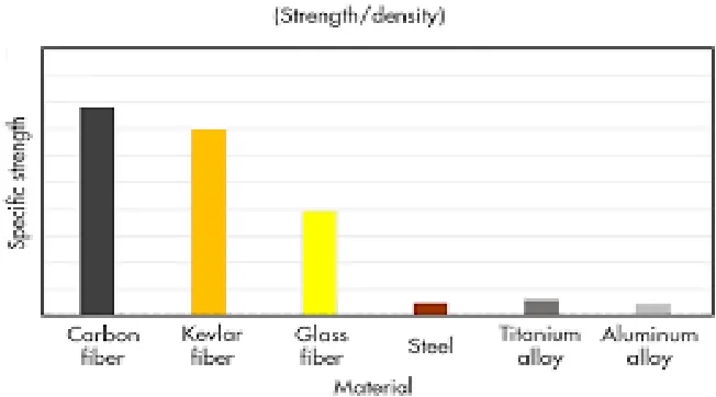
1) CARBON FIBER-REINFORCED EPOXY composites exhibit high specific strength, high specific stiffness and good fatigue
tolerance Furthermore, the fabrication of components and structures from composites allows for the integration of design principles and manufacturing processes, resulting in optimally tailored mechanical and physical characteristics.
2) Epoxy resins are typically about three times stronger than the next strongest resin type. Epoxy adheres to Carbon Fibre, Fibre
glass, and Aramid (Kevlar), very well and forms a virtually leak- proof barrier.
3) The epoxy can undergo plasticization and hydrolysis, which cause reversible and irreversible changes in the polymer structure.
[image:4.612.143.469.470.651.2]Due to these processes both the modulus and glass transition temperature are lowered
FIG 3: Graph showing strength of Carbon Fiber Material
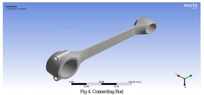
Fig 4. Connecting Rod
G. Structural Analysis
Analysis is carried out on connecting rod made of both the materials, whose properties are tabulated as given below
H. Properties of Steel
STEEL
YOUNGS MODULUS (Pa) 2e11
POISON RATIO 0.29
DENSITY (kg/m^3) 7850
YEID STRNGTH (Pa) 2.5e8
I. Properties of Composite Material Carbon Fiber Epoxy
CARBON FIBRE EPOXY
YOUNGS MODULUS(Mpa) Exx 91820
YOUNGS MODULUS(Mpa) Eyy 91820
YOUNGS MODULUS(Mpa) Ezz 9000
POISSON RATIO xy 0.05
POISSON RATIO yz 0.3
POISSON RATIO zx 0.3
DENSITY (kg/m^3) 1480
FIG 5: Connecting Rod in Meshing
FIG 5: Analysis on Connecting Rod made of Steel in ANSYS 14.5
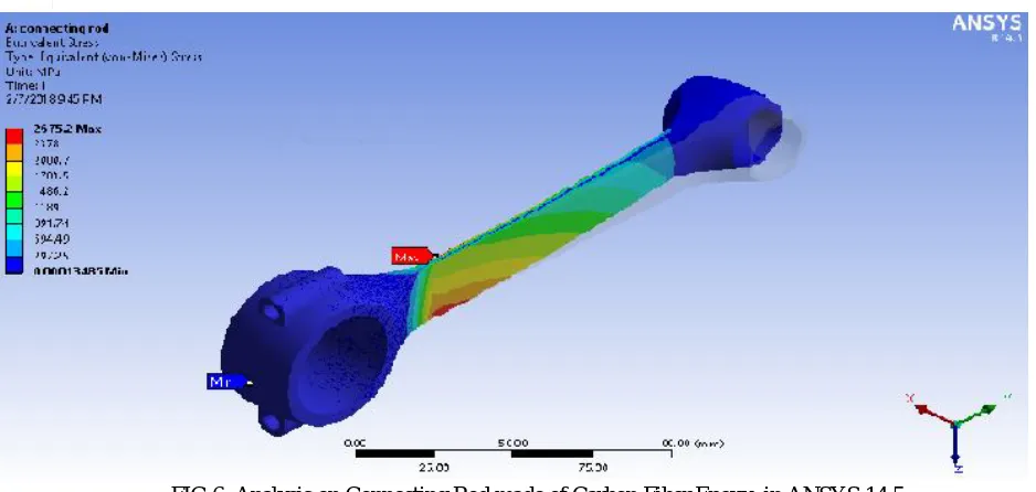
Results for Connecting Rod made of Carbon Fiber Epoxy
Structural steel Carbon epoxy fiber
FIG 6: Analysis on Connecting Rod made of Carbon Fiber Epoxy in ANSYS 14.5
III. CONCLUSION
A. From the results of structural analysis, we can say that due to the less stress induced , connecting rod made with carbon fiber
epoxy material shows good mechanical properties as compared with the connecting rod made of steel.
B. As carbon fiber is light in weight and has good elasticity property thus reduce inertia loads, reducing engine weight and
improving engine performance.
REFERENCES
[1] Kuldeep B, Arun L.R, Mohammed Faheem “Analysis and Optimisation of Connecting Rod using Alfasic Composites”, ISSN: 2319-8753 International Journal of Innovative Research in Science, Engineering and Technology vol.2, Issue 6, June 2013
[2] GVSS Sharma and P Srinivasa Rao “Process Capability Improvement of an Engine Connecting Rod Machining Process “Journal of Industrial Engineering International 2013, 9:37 doi:10.1186/2251-712X-9-37
[3] Bhuptani K.M “Structural Analysis of Bush Bearing for small end connecting rod using “PROMECHANICA” ISSN 0975-668X, Nov12 to Oct13, Volume-o2. 2344-02
[4] Abhinav Gautam, K Priya Ajit “Static Stress Analysis of Connecting Rod using Finite Element Approach” IOSR Journal of Mechanical and Civil Engineering (IOSR-JMCE) e-ISSN: 2278-1684, p-ISSN 2320-334X, Volume 10, Issue 1 (Nov-Dec. 2013), pp 47-51