University of Huddersfield Repository
Asim, TaimoorComputational Fluid Dynamics Based Diagnostics and Optimal Design of Hydraulic Capsule Pipelines
Original Citation
Asim, Taimoor (2013) Computational Fluid Dynamics Based Diagnostics and Optimal Design of Hydraulic Capsule Pipelines. Doctoral thesis, University of Huddersfield.
This version is available at http://eprints.hud.ac.uk/id/eprint/17805/
The University Repository is a digital collection of the research output of the University, available on Open Access. Copyright and Moral Rights for the items on this site are retained by the individual author and/or other copyright owners. Users may access full items free of charge; copies of full text items generally can be reproduced, displayed or performed and given to third parties in any format or medium for personal research or study, educational or notforprofit purposes without prior permission or charge, provided:
• The authors, title and full bibliographic details is credited in any copy; • A hyperlink and/or URL is included for the original metadata page; and • The content is not changed in any way.
For more information, including our policy and submission procedure, please contact the Repository Team at: [email protected].
C
OMPUTATIONAL
F
LUID
D
YNAMICS
B
ASED
D
IAGNOSTICS AND
O
PTIMAL
D
ESIGN OF
H
YDRAULIC
C
APSULE
P
IPELINES
A THESIS SUBMITTED IN PARTIAL FULFILMENT OF THE REQUIREMENTS FOR THE DEGREE OF DOCTOR OF PHILOSOPHY AT THE UNIVERSITY OF HUDDERSFIELD
by
Taimoor Asim
B.Eng. National University of Sciences and Technology, PAK, 2007 M.Sc. University of Huddersfield, UK, 2008
Director of Research: Prof. Rakesh Mishra
Leader of Energy, Emissions and the Environment Research Group
A
BSTRACT
Scarcity of fossil fuels and rapid escalation in the energy prices around the world is affecting efficiency of established modes of cargo transport within transportation industry. Extensive research is being carried out on improving efficiency of existing modes of cargo transport, as well as to develop alternative means of transporting goods. One such alternative method can be through the use of energy contained within fluid flowing in pipelines in order to transfer goods from one place to another. Although the concept of using fluid pipelines for transportation purposes has been in practice for more than a millennium now, but the detailed knowledge of the flow behaviour in such pipelines is still a subject of active research. This is due to the fact that most of the studies conducted on transporting goods in pipelines are based on experimental measurements of global flow parameters, and only a rough approximation of the local flow behaviour within these pipelines has been reported. With the emergence of sophisticated analytical tools and the use of high performance computing facilities being installed throughout the globe, it is now possible to simulate the flow conditions within these pipelines and get better understanding of the underlying flow phenomena.
The present study focuses on the use of advanced modelling tools to simulate the flow within Hydraulic Capsule Pipelines (HCPs) in order to quantify the flow behaviour within such pipelines. Hydraulic Capsule Pipeline is the term which refers to the transport of goods in hollow containers, typically of spherical or cylindrical shapes, termed as capsules, being carried along the pipeline by water. A novel modelling technique has been employed to carry out the investigations under various geometric and flow conditions within HCPs.
Both qualitative and quantitative flow diagnostics has been carried out on the flow of both spherical and cylindrical shaped capsules in a horizontal HCP for on-shore applications. A train of capsules consisting of a single to multiple capsules per unit length of the pipeline has been modelled for practical flow velocities within HCPs. It has been observed that the flow behaviour within HCP depends on a number of fluid and geometric parameters. The pressure drop in such pipelines cannot be predicted from established methods. Development of a predictive tool for such applications is one of the aims that is been achieved in this study. Furthermore, investigations have been conducted on vertical pipelines as well, which are very important for off-shore applications of HCPs. The energy requirements for vertical HCPs are significantly higher than horizontal HCPs. It has been shown that a minimum average flow velocity is required to transport a capsule in a vertical HCP, depending upon the geometric and physical properties of the capsules. The concentric propagation, along the centreline of pipe, of heavy density capsules in vertical HCPs marks a significant variation from horizontal HCPs transporting heavy density capsules.
Optimisation of HCPs plays a crucial rule towards worldwide commercial acceptability of such pipelines. Based on Least-Cost Principle, an optimisation methodology has been developed for single stage HCPs for both on-shore and off-shore applications. The input to the optimisation model is the solid throughput required from the system, and the outputs are the optimal diameter of the HCPs and the pumping requirements for the capsule transporting system. The optimisation model presented in the present study is both robust and user-friendly.
D
ECLARATION
The author of this thesis (including any appendices and/or schedules to this thesis) owns any copyright in it (the “Copyright”) and he has given The University of Huddersfield the right to use such Copyright for any administrative, promotional, educational and/or teaching purposes.
Copies of this thesis, either in full or in extracts, may be made only in accordance with the regulations of the University Library. Details of these regulations may be obtained from the Librarian. This page must form part of any such copies made.
A
CKNOWLEDGEMENTS
It is a great pleasure to acknowledge the efforts and support of those who have, directly or indirectly, contributed towards the creation of this thesis. Foremost, I would like to thank almighty Allah for giving me the opportunity to be on this planet and contribute in whatever capacity I can, towards the betterment of the human race. Secondly, I would like to acknowledge the contributions made by my parents, Mr. and Mrs. Aftab Iqbal, in terms of moral, emotional and financial support throughout my growing years and especially my mother who always took great interest in my academic carrier.
No other person, living or dead, has directly contributed more than my supervisor Prof. Rakesh Mishra towards making this thesis a reality. His constant efforts, guidance and support have always been iconic to me. His dynamic nature, versatile skills and command over Fluid Dynamics helped me learn a lot from him. I would like to thank him for teaching me scientific writing skills and for the opportunity of participation in various international conferences. One simply could not wish a better or friendlier supervisor.
I would like to acknowledge the support and friendship of my colleagues at the Energy, Emissions and Environment Research group at the University of Huddersfield, especially my co-supervisor Prof. Vasudeva Rao for his considerable help in the modelling and design of fluid flows. I would like to acknowledge the support provided by other research groups such as Diagnostics, CPT and HPC to name a few of them. I would also like to acknowledge the support of the administrative staff at the School of Computing and Engineering and the technicians in both the Technology and Canal Side buildings at the University of Huddersfield. Furthermore, I would like to acknowledge the researchers around the globe whose work has been reproduced in this thesis without permission, in the form of figures (mostly in Chapter 2). I presume that they wouldn‟t have disagreed to reproduce their work if I would have contacted them, which I wouldn‟t able to do due to shortage of time and in some cases due to insufficient contact information.
C
ONTENTS
ABSTRACT ... iv
DECLARATION ... vi
ACKNOWLEDGEMENTS ... vii
CONTENTS ... viii
LIST OF FIGURES ... xiv
LIST OF TABLES ...xxviii
NOMENCLATURE ... xxx
SYMBOLS ...xxxii
SUBSCRIPTS ... xxxiii
CHAPTER 1 INTRODUCTION ...1
1.1. Pipeline Transport ...2
1.2. Pressure Drop Considerations in Hydraulic Pipelines ...3
1.2.1. Horizontal Pipelines ...4
1.2.2. Vertical Pipelines ...5
1.2.3. Pipeline Bends ...6
1.3. Transport of Capsules in Pipelines ...6
1.4. History of Hydraulic Capsule Pipelines ...7
1.5. Components of a Hydraulic Capsule Pipeline ...9
1.5.1. Pump ...9
1.5.2. Capsules ... 10
1.5.3. Capsule Injection System ... 10
1.5.4. Capsule Ejection System ... 11
1.6. Mechanics of Transportation of Solids in Pipelines ... 11
1.6.1. Design Considerations for Pipelines Transporting Capsules ... 12
1.7. Pressure Drop Considerations in Hydraulic Capsule Pipelines ... 14
1.7.1. Horizontal Pipelines ... 15
1.7.3. Pipeline Bends ... 16
1.8. Motivation ... 17
1.9. Research Aims ... 18
1.10. Organization of Thesis... 19
CHAPTER 2 LITERATURE REVIEW ... 21
2.1. Horizontal HCPs ... 22
2.1.1. Summary of Literature regarding Horizontal HCPs ... 28
2.2. Vertical HCPs ... 28
2.2.1. Summary of Literature regarding Vertical HCPs ... 31
2.3. HCP Bends ... 32
2.3.1. Summary of Literature regarding HCP Bends... 34
2.4. HCP‟s Optimisation ... 35
2.4.1. Summary of Literature regarding Optimisation of HCPs ... 37
2.5. Scope of Research ... 37
2.6. Specific Research Objectives ... 38
CHAPTER 3 CFDMODELLING OF HYDRAULIC CAPSULE PIPELINES ... 39
3.1. Pre-Processing ... 40
3.1.1. Pipe and Bend Geometries ... 40
3.1.2. Capsule Geometries ... 41
3.1.3. Meshing of the Flow Domain ... 44
3.2. Solver Execution ... 45
3.2.1. Selection of the Physical Models ... 45
3.2.2. Defining Material Properties and Operating Conditions ... 47
3.2.3. Boundary Conditions ... 47
3.2.4. Capsule Velocities in Horizontal HCPs ... 48
3.2.5. Capsule Velocities in Vertical HCPs ... 53
3.2.6. Capsule Velocities in Bends ... 54
3.2.7. Solver Settings ... 55
3.2.8. Convergence Criteria ... 56
4.3. Mesh Independence Tests ... 63
4.4. Benchmark Tests ... 64
4.5. Analysis of the Flow of Equi-Density Spherical Capsules in a Horizontal HCP ... 65
4.5.1. Average Flow Velocity Effects ... 68
4.5.2. Capsule Diameter Effects ... 70
4.5.3. Capsule Concentration Effects ... 71
4.5.4. Effects of Spacing between the Capsules ... 72
4.6. Analysis of the Flow of Equi-Density Cylindrical Capsules in a Horizontal HCP ... 76
4.6.1. Average Flow Velocity Effects ... 78
4.6.2. Length of the Capsule Effects ... 80
4.6.3. Capsule Diameter Effects ... 81
4.6.4. Capsule Concentration Effects ... 81
4.6.5. Effects of Spacing between the Capsules ... 83
4.7. Analysis of the Flow of Heavy-Density Spherical Capsules in a Horizontal HCP ... 87
4.7.1. Average Flow Velocity Effects ... 90
4.7.2. Capsule Diameter Effects ... 91
4.7.3. Capsule Concentration Effects ... 92
4.7.4. Effects of Spacing between the Capsules ... 93
4.8. Analysis of the Flow of Heavy-Density Cylindrical Capsules in a Horizontal HCP ... 96
4.8.1. Average Flow Velocity Effects ... 99
4.8.2. Length of the Capsule Effects ... 100
4.8.3. Capsule Diameter Effects ... 101
4.8.4. Capsule Concentration Effects ... 102
4.8.5. Effects of Spacing between the Capsules ... 103
4.9. Prediction Models ... 107
4.10. Summary of the Analysis of a Horizontal HCP ... 110
CHAPTER 5 ANALYSIS OF VERTICAL PIPELINES TRANSPORTING CAPSULES ... 112
5.1. Analysis of Single Phase Flow in a Vertical Pipe ... 113
5.2. Analysis of the Flow of Equi-Density Spherical Capsules in a Vertical HCP ... 116
5.2.1. Average Flow Velocity Effects ... 119
5.2.2. Capsule Diameter Effects ... 120
5.2.4. Effects of Spacing between the Capsules ... 123
5.3. Analysis of the Flow of Equi-Density Cylindrical Capsules in a Vertical HCP ... 126
5.3.1. Average Flow Velocity Effects ... 128
5.3.2. Length of the Capsule Effects ... 130
5.3.3. Capsule Diameter Effects ... 131
5.3.4. Capsule Concentration Effects ... 131
5.3.5. Effects of Spacing between the Capsules ... 132
5.4. Analysis of the Flow of Heavy-Density Spherical Capsules in a Vertical HCP ... 136
5.4.1. Average Flow Velocity Effects ... 140
5.4.2. Capsule Diameter Effects ... 141
5.4.3. Capsule Concentration Effects ... 142
5.4.4. Effects of Spacing between the Capsules ... 144
5.5. Analysis of the Flow of Heavy-Density Cylindrical Capsules in a Vertical HCP... 146
5.5.1. Average Flow Velocity Effects ... 149
5.5.2. Length of the Capsule Effects ... 151
5.5.3. Capsule Diameter Effects ... 152
5.5.4. Capsule Concentration Effects ... 153
5.5.5. Effects of Spacing between the Capsules ... 154
5.6. Prediction Models ... 157
5.7. Summary of the Analysis of a Vertical HCP ... 160
CHAPTER 6 ANALYSIS OF BENDS TRANSPORTING CAPSULES ... 161
6.1. Analysis of Single Phase Flow in Horizontal Bends ... 162
6.1.1. Average Flow Velocity Effects ... 162
6.1.2. Effects of Radius of Curvature ... 163
6.2. Analysis of the Flow of Equi-Density Capsules in Horizontal Bends ... 164
6.2.1. Average Flow Velocity Effects ... 164
6.2.2. Capsule Diameter Effects ... 165
6.2.3. Capsule Concentration Effects ... 166
6.2.4. Effects of Spacing between the Capsules ... 166
6.3. Analysis of the Flow of Heavy-Density Capsules in Horizontal Bends ... 169
6.3.1. Average Flow Velocity Effects ... 170
6.3.2. Capsule Diameter Effects ... 171
6.3.3. Capsule Concentration Effects ... 171
6.3.4. Effects of Spacing between the Capsules ... 172
6.3.5. Effects of Radius of Curvature of the Bend ... 173
6.3.6. Capsule Shape Effects ... 173
6.3.7. Length of the Capsule Effects ... 174
6.4. Analysis of Single Phase Flow in Vertical Bends ... 175
6.4.1. Average Flow Velocity Effects ... 175
6.4.2. Effects of Radius of Curvature ... 176
6.5. Analysis of the Flow of Equi-Density Capsules in Vertical Bends ... 177
6.5.1. Average Flow Velocity Effects ... 178
6.5.2. Capsule Diameter Effects ... 178
6.5.3. Capsule Concentration Effects ... 179
6.5.4. Effects of Spacing between the Capsules ... 180
6.5.5. Effects of Radius of Curvature of the Bend ... 180
6.5.6. Capsule Shape Effects ... 181
6.5.7. Length of the Capsule Effects ... 182
6.6. Analysis of the Flow of Heavy-Density Capsules in Vertical Bends ... 182
6.6.1. Average Flow Velocity Effects ... 183
6.6.2. Capsule Diameter Effects ... 184
6.6.3. Capsule Concentration Effects ... 184
6.6.4. Effects of Spacing between the Capsules ... 185
6.6.5. Effects of Radius of Curvature of the Bend ... 186
6.6.6. Capsule Shape Effects ... 186
6.6.7. Length of the Capsule Effects ... 187
6.7. Prediction Models ... 188
6.8. Summary of the Analysis of a HCP Bends ... 191
CHAPTER 7 OPTIMISATION OF HCPS ... 193
7.1. Introduction ... 194
7.3. Cost of Pipes ... 195
7.4. Cost of Capsules ... 195
7.5. Cost of Power ... 195
7.6. Mixture Flow Rate ... 196
7.7. Total Pressure Drop ... 196
7.8. Solid Throughput ... 197
7.9. Working of the Optimisation Model ... 198
7.10. Limitations of the Optimisation Model ... 201
7.11. Design Example for On-Shore Applications ... 201
7.11.1. Comparison of the Optimisation Model w.r.t. Agarwal et. al.‟s [66] Optimisation Model ... 205
7.11.2. Capsule Shape Effects ... 206
7.11.3. Effects of the Density of the Capsules ... 211
7.12. Design Example for Off-Shore Applications ... 215
7.12.1. Capsule Shape Effects ... 219
7.12.2. Effects of the Density of the Capsules ... 223
7.13. Summary of HCP‟s Optimisation ... 226
CHAPTER 8 CONCLUSIONS ... 228
8.1. Research Problem Synopsis... 229
8.2. Research Aims and Major Achievements... 229
8.3. Thesis Conclusions ... 232
8.4. Thesis Contributions ... 236
8.5. Recommendations for Future Work ... 237
REFERENCES ... 239
APPENDICES ... 247
A-1: Computational Fluid Dynamics ... 247
A-2: Capsule Velocities ... 253
A-3: Pressure Drop in Horizontal HCPs ... 280
A-4: Pressure Drop in Vertical HCPs ... 290
A-5: Pressure Drop in HCP Bends ... 300
L
IST OF
F
IGURES
Figure 1.1. Flow in a Horizontal Pipe ... 3
Figure 1.2. The Lilo-1 system [12] ... 8
Figure 1.3. Sumitomo Metal Industries [13] ... 8
Figure 1.4. Magplane Technology [15] ... 9
Figure 1.5. Top View of Pump for Pipelines transporting Capsules [16] ... 10
Figure 1.6. Capsule Injection System (a) Side View (b) Top View [18] ... 11
Figure 2.1. Prediction of Holdup in Equi-Density Spherical Capsules [24] ... 23
Figure 2.2. Relation between ∆P/Lm and Re of Mixture based on Experiments [26] ... 24
Figure 2.3. Characteristics near Capsule for (a) Elastic and (b) Rigid Capsule Models [32] ... 26
Figure 2.4. The Predicted Effect of k on the Holdup at various Solid Throughputs ... 27
Figure 2.5. The Relation between the Balance Velocity and the Inclination Angle (a) k = 0.664 (b) k = 0.507 (c) k = 0.403 [46] ... 29
Figure 2.6. Distributions of Turbulent Intensity (a) k = 0.9 (b) k = 0.67 [47] ... 30
Figure 2.7. Pneumatic, Steadily Moving Capsule [50] ... 31
Figure 2.8. Effect of Bend Central Angle on Velocity Ratio of Capsule in Bend [53] ... 32
Figure 2.9. Pressure Losses through Various Regions in a Horizontal Bend [57] ... 33
Figure 2.10. Single and Multiphase Pressure Drop [61] ... 34
Figure 2.11. Operation of TLIM Capsule Pump [63] ... 35
Figure 2.12. Hoist Description [65] ... 36
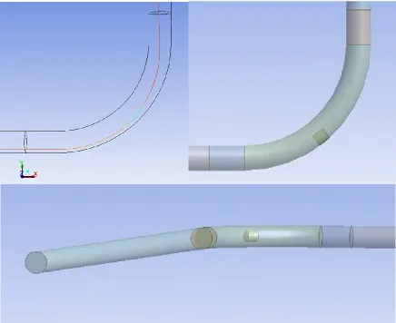
Figure 3.1. Geometry of the Pipe ... 40
Figure 3.2. Geometry of the Bends ... 41
Figure 3.4. Geometry of Heavy-Density Cylindrical Capsules ... 42
Figure 3.5. Trajectory of Heavy-Density Spherical Capsules in HCP Bends ... 43
Figure 3.6. Trajectory of Equi-Density Cylindrical Capsules in HCP Bends ... 44
Figure 3.7. Meshing of the Flow Domain ... 45
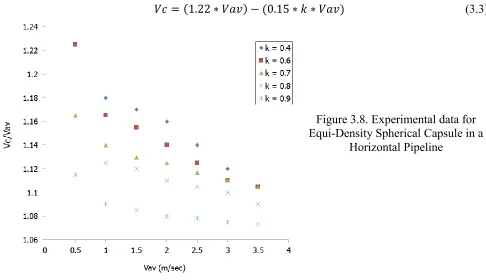
Figure 3.8. Experimental data for Equi-Density Spherical Capsule in a Horizontal Pipeline ... 48
Figure 3.9. Curve fitting on the experimental data for Equi-Density Spherical Capsule in a Horizontal Pipeline .... 49
Figure 3.10. Experimental data for Heavy-Density Spherical Capsule in a Horizontal Pipeline ... 50
Figure 3.11. Curve fitting for Heavy-Density Spherical Capsule in a Horizontal Pipeline ... 51
Figure 3.12. Experimental data for Heavy-Density Cylindrical Capsule in a Horizontal Pipeline ... 52
Figure 3.13. Curve fitting for Heavy-Density Cylindrical Capsule in a Horizontal Pipeline ... 53
Figure 4.1. Pressure Variations for Water Flow in a Horizontal Pipe ... 58
Figure 4.2. Variations in Cp for Water Flow in a Horizontal Pipe ... 59
Figure 4.3. Velocity Distribution for Water Flow in a Horizontal Pipe ... 61
Figure 4.4. Velocity Profile for Water Flow in a Horizontal Pipe ... 61
Figure 4.5. Entrance Length Effects for Water Flow in a Horizontal Pipe ... 62
Figure 4.6. Analysis Line for the flow of (a) An Equi-Density Spherical Capsule (b) A Heavy-Density Cylindrical Capsule, in a Horizontal Pipe ... 63
Figure 4.7. Validation of the CFD results w.r.t. the Experimental results, for the Pressure Drop in a Horizontal Pipe, Transporting Equi-Density Spherical Capsules, at Various Flow Velocities ... 65
Figure 4.8. Variations in (a) Pressure and (b) Velocity, for a Single Spherical Capsule of k = 0.5 in a Horizontal Pipe at Vav = 1m/sec ... 66
Figure 4.9. (a) Variations in Cp for a Single Spherical Capsule of k = 0.5 in a Horizontal Pipe at Vav = 1m/sec (b) Variations in u/umax for a Single Spherical Capsule of k = 0.5 in a Horizontal Pipe at Vav = 1m/sec ... 67
Figure 4.10. Variations in the Cross-Sectional Velocity Profiles for a Single Spherical Capsule of k = 0.5 in a Horizontal Pipe at Vav = 1m/sec at (a) Upstream and (b) Downstream of the Capsule ... 68
Figure 4.72. fc for Heavy-Density Cylindrical Capsules ... 110
Figure 5.1. Pressure variations for Water Flow in a Vertical Pipe ... 113
Figure 5.2. Variations in Cp for Water Flow in a Vertical Pipe ... 114
Figure 5.3. Velocity distribution for Water Flow in a Vertical Pipe ... 115
Figure 5.4. Velocity Profile for Water Flow in a Vertical Pipe ... 115
Figure 5.5. Variations in (a) Pressure and (b) Velocity, for a Single Spherical Capsule of k = 0.5 in a Vertical Pipe at Vav = 1m/sec ... 116
Figure 5.6. (a) Variations in Cp for a Single Spherical Capsule of k = 0.5 in a Vertical Pipe at Vav = 1m/sec (b) Variations in u/umax for a Single Spherical Capsule of k = 0.5 in a Vertical Pipe at Vav = 1m/sec ... 117
Figure 5.7. Variations in the Cross-Sectional Velocity Profiles for a Single Spherical Capsule of k = 0.5 in a Vertical Pipe at Vav = 1m/sec at (a) Upstream and (b) Downstream of the Capsule ... 118
Figure 5.8. Development of Velocity Profile in the Presence of a Single Spherical Capsule in a Vertical Pipe having Density Equal to Water ... 118
Figure 5.9. Variations in (a) Pressure and (b) Velocity, for a Single Spherical Capsule of k = 0.5 in a Vertical Pipe at Vav = 4m/sec ... 119
Figure 5.10. (a) Variations in Cp for a Single Spherical Capsule of k = 0.5 in a Vertical Pipe at Vav = 4m/sec (b) Variations in u/umax for a Single Spherical Capsule of k = 0.5 in a Vertical Pipe at Vav = 4m/sec ... 120
Figure 5.11. Variations in (a) Pressure and (b) Velocity, for a Single Spherical Capsule of k = 0.9 in a Vertical Pipe at Vav = 1m/sec ... 120
Figure 5.12. (a) Variations in Cp for a Single Spherical Capsule of k = 0.5 in a Vertical Pipe at Vav = 1m/sec (b) Variations in u/umax for a Single Spherical Capsule of k = 0.5 in a Vertical Pipe at Vav = 1m/sec ... 121
Figure 5.13. Variations in (a) Pressure and (b) Velocity, for Three Spherical Capsules of k = 0.5 and Sc = 1 * d in a Vertical Pipe at Vav = 1m/sec ... 122
Figure 5.14. (a) Variations in Cp for Three Spherical Capsules of k = 0.5 and Sc = 1 * d in a Vertical Pipe at Vav = 1m/sec (b) Variations in u/umax for Three Spherical Capsules of k = 0.5 and Sc = 1 * d in a Vertical Pipe at Vav = 1m/sec ... 122
Figure 5.15. Variations in (a) Pressure and (b) Velocity, for Three Spherical Capsules of k = 0.5 and Sc = 5 * d in a Vertical Pipe at Vav = 1m/sec ... 123
Figure 5.17. Variations in Normalised Pressure Drop for a Single Equi-Density Spherical Capsule in a Vertical Pipe ... 124 Figure 5.18. Variations in Normalised Pressure Drop for Three Equi-Density Spherical Capsules in a Vertical Pipe ... 125 Figure 5.19. Variations in Normalised Pressure Drop for Three Spherical Capsules of k = 0.7 in a Vertical Pipe ... 125 Figure 5.20. Variations in (a) Pressure and (b) Velocity, for a Cylindrical Capsule of k = 0.5 and Lc = 1 * d in a Vertical Pipe at Vav = 1m/sec ... 126 Figure 5.21. (a) Variations in Cp for a Cylindrical Capsule of k = 0.5 and Lc = 1 * d in a Vertical Pipe at Vav = 1m/sec (b) Variations in u/umax for a Cylindrical Capsule of k = 0.5 and Lc = 1 * d in a Vertical Pipe at Vav = 1m/sec ... 127 Figure 5.22. Variations in the Cross-Sectional Velocity Profiles for a Single Cylindrical Capsule of k = 0.5 and Lc = 1 * d in a Vertical Pipe at Vav = 1m/sec at (a) Upstream and (b) Downstream of the Capsule ... 127 Figure 5.23. Development of Velocity Profile in the Presence of a Single Cylindrical Capsule in a Vertical Pipe having Density Equal to Water ... 128 Figure 5.24. Variations in (a) Pressure and (b) Velocity, for a Cylindrical Capsule of k = 0.5 and Lc = 1 * d in a Vertical Pipe at Vav = 4m/sec ... 129 Figure 5.25. (a) Variations in Cp for a Cylindrical Capsule of k = 0.5 and Lc = 1 * d in a Vertical Pipe at Vav = 4m/sec (b) Variations in u/umax for a Cylindrical Capsule of k = 0.5 and Lc = 1 * d in a Vertical Pipe at Vav = 4m/sec ... 129 Figure 5.26. Variations in (a) Pressure and (b) Velocity, for a Single Cylindrical Capsule of k = 0.5 and Lc = 5 * d in a Vertical Pipe at Vav = 1m/sec ... 130 Figure 5.27. (a) Variations in Cp for a Single Cylindrical Capsule of k = 0.5 and Lc = 5 * d in a Vertical Pipe at Vav = 1m/sec (b) Variations in u/umax for a Single Cylindrical Capsule of k = 0.5 and Lc = 5 * d in a Vertical Pipe at Vav = 1m/sec ... 130
L
IST OF
T
ABLES
Table 7.13. Variations in Pumping Power and Various Costs w.r.t. Pipeline Diameter ... 215 Table 7.14. Variations in Capsule Velocity and Pressure Drop ... 217 Table 7.15. Variations in Optimal Diameter, Capsule Velocity and Pumping Power for Various Solid Throughputs 218
N
OMENCLATURE
A Cross-sectional Area of the Pipe (m2)
C1 Cost of Power consumption per unit Watt (£/W) C2 Cost of Pipe per unit Weight of Pipe material (£/N)
C3 Cost of Capsules per unit Weight of the Capsule Material (£/N) Cc Constant of Proportionality
Cp Coefficient of Pressure c Concentration of Solid Phase d Diameter of Capsule (m) D Diameter of Pipe (m) f Darcy Friction Factor
Fr Froud Number
g Acceleration due to gravity (m/sec2)
h Elevation (m)
hl Head loss (m)
H Holdup
k Capsule to Pipe diameter ratio Kl Loss Coefficient of Bends
L Length (m)
n Number of Bends
N Number of Capsules
r Radius of Curvature of Pipe Bend (m) R Radius of Pipe Bend (m)
Re Reynolds Number
s Specific Gravity
Sc Spacing between the Capsules (m)
u Local Flow Velocity in X direction (m/sec) V Flow Velocity (m/sec)
x Axial Distance (m)
S
YMBOLS
α Function of Reynolds Number ρ Density (Kg/m3)
μ Dynamic Viscosity (Pa-sec) ϒ Specific Weight (N/m3) η Efficiency of the Pump (%) ε Roughness Height of the Pipe (m) θ Angular Position (ᴼ)
л Pi
Specific Internal Energy (J/Kg)
ψ Shape Factor
σ Normal Stress (Pa)
Shear Stress (Pa)
S
UBSCRIPTS
av Average
b Bulk
c Capsule
cn Centreline
e Entrance
h Horizontal
m Mixture
p Pipe
v Vertical
w Water
INTRODUCTION
C
HAPTER
1
I
NTRODUCTION
ipelines are an integral part of various industries. Pipes used for on-shore applications largely consist of horizontal pipes. The third generation of horizontal pipes consist of pipes, transporting capsules. In order to effectively analyse the underlying complex flow phenomena occurring in hydraulic pipelines transporting capsules it is essential to first understand the flow structure within a hydraulic pipeline. The pressure drop co-relations for a hydraulic pipeline can be extended to incorporate the effects of the presence of solid phase in the pipelines. Hence, this chapter provides an introductory discussion regarding water flow and capsule flow in pipelines. Furthermore, this chapter provides with the details of the capsule pipeline components and design requirements.
1.1.
Pipeline Transport
Pipeline transport is the transportation of goods through a pipe. Pipelines have long been used as a medium of transport. The history of pipeline transport can be divided into three generations. The first generation of pipelines comprises transport of a single phase within these pipelines. The single phase usually consists of a fluid; either a liquid or a gas. The history of first generation of pipelines dates back to 189 AD when a court of Han Dynasty ordered an engineer to construct a series of square-pallet chain pumps outside the capital city. Around the same time, Romans made use of large aqueducts to transport water from a higher elevation to a lower elevation. These aqueducts were quite famous throughout the Europe [1].
The second generation of pipelines consists of the transport of multiple phases in the pipelines. These multiple phases make use of the combination of solids, liquids and gases such as liquid-liquid (e.g. Oil in water etc.), liquid-gas (e.g. bubbly flow etc.), liquid-solid (e.g. slurry flow etc.) or even liquid-gas-solid flow. The slurry pipeline, in specific, has gained a lot of importance due to it being economically viable to the industries throughout the world for the transportation of solid materials. The solid medium usually consists of solid particles with diameter ranging from a few microns to a few millimetres. It is an effective medium of transport of solids such as coal, sand etc.
The third generation of pipelines comprises of the transportation of Capsules. These capsules are hollow containers filled with minerals, ores, radioactive materials or even goods such as mail, jewellery etc. In some cases, the material that needs to be transported is itself given the shape of the capsule. This technique is very famous in the transportation of coal, and such pipelines are termed as Coal-Log Pipelines (CLP) [2]. The shape of the capsule is normally cylindrical or spherical where wheels are usually attached to the cylindrical capsules to overcome the enormous static friction between the capsules and the pipe wall because of a larger contact area as compared to spherical capsules. The economic surveys that have been conducted by some companies and universities, have shown that the capsule transportation is more economical than conventional methods of transporting goods such as trucks, rails etc. [3]. Furthermore, the pipelines transporting capsules provide additional benefits such as [4]:
The capsule transporting phenomena is quiet and hence is environment friendly as compared to conventional transporting methods
There are no accidents or delays due to traffic reasons, and hence it is faster and safer for the goods being transported
There is no man power required for the transporting phenomenon except at the injection and evacuation of the capsules from the pipeline
Except CLP, the solid medium remains intact as there is no direct contact between the goods being transported and the transporting medium
INTRODUCTION
High degree of efficiency and reliability Simplicity of installation
Can be readily automated
1.2.
Pressure Drop Considerations in Hydraulic Pipelines
Pipeline flows have always been a topic of research throughout the world. Daniel Bernoulli (1700 – 1782 AD), a Swiss mathematician and physicist, while working on the principles of conservation of energy, realised that a moving fluid exchanges its kinetic energy with pressure. In his famous publication „Hydrodynamica‟, Bernoulli states that “for an inviscid fluid flow, an increase in the fluid velocity results in a decrease in its pressure”. This is known as Bernoulli‟s principle and can be mathematically written as [5]:
(1.1)
where P represents the static pressure of the fluid, ρ is the density of the fluid and u is the velocity of the fluid. The second term on the left-hand side of the equation represents the dynamic pressure. A more general form of this law, in which the effects of the elevation and the head loss in the pipeline has also been considered, is:
(1.2)
where g is the gravitational acceleration, h is the vertical elevation and hl is the head loss experienced by the fluid. Subscripts 1 and 2 represent station 1 and 2 respectively as shown in figure 1.1.
Figure 1.1. Flow in a Horizontal Pipe
difference of 100m, the variation in gravitational acceleration is << 1m/sec2. Hence, the gravitational acceleration can be considered constant for general-purpose pipelines.
1.2.1. Horizontal Pipelines
Considering incompressible flow and constant gravitational acceleration in a horizontal pipeline, equation (1.2) becomes:
(1.3)
(
)
(
)
(1.4)
The flow rate in a pipe can be represented by:
(1.5)
where Q is the flow rate of the fluid, V is the velocity of the fluid and A is the cross-sectional area of the pipe. The pipe considered in figure 1 has a constant diameter throughout its length, which further suggests that the cross-sectional area of the pipe remains constant. Furthermore, to satisfy the equilibrium condition, the flow rate at station 1 should be equal to flow rate at station 2.
(1.6)
(1.7)
Now, as A1 = A2 this implies that the velocity at station 1 should be equal to velocity at station 2.
(1.8)
For such a case, equation (1.4) becomes:
(
)
(1.9) or,
(1.10)
where is the pressure drop in the fluid between the two stations. Darcy-Weisbach equation, named after Henry Darcy (1803 – 1858 AD) and Julius Weisbach (1806 – 1871 AD), relates the head loss to the velocity of the fluid, and can be mathematically represented as [6]:
INTRODUCTION
where f is the Darcy Friction Factor, Lp is the length and D is the diameter of the pipe. Putting equation (1.11) into equation (1.10):
(1.12)
The Darcy friction factor can be computed from Moody‟s chart; developed by Lewis Ferry Moody in 1944 AD. It is a function of the relative pipe roughness (ε/D) and the Reynolds number of the fluid, where ε is the absolute pipe roughness in meters. The Reynolds number can be represented by [7]:
(1.13)
where μ is the dynamic viscosity of the fluid. It value is 0.001003Pa-sec for water at 20⁰C and 1bar
atmospheric pressure.
1.2.2. Vertical Pipelines
Considering incompressible flow and constant gravitational acceleration in a vertical pipeline, equation (1.2) becomes:
(1.14)
(
)
(
) (
)
(1.15)
For a constant diameter pipe, equation (1.15) becomes:
(
) (
)
(1.16)
(1.17)
(1.18)
1.2.3. Pipeline Bends
The pressure drop occurring within horizontal pipeline bends is represented in terms of the loss coefficient of the bends as [8]:
(1.19)
and the pressure drop occurring within vertical pipeline bends is represented in terms of the loss coefficient of the bends as:
(1.20)
1.3.
Transport of Capsules in Pipelines
Capsule pipelines are used to transport solid materials using water or any other liquid as a carrier fluid. This mode of transportation is suited for long distance haulage of bulk materials like mineral ore to processing plants, coal to thermal power plants, disposal of waste material, like fly ash, from processing plant to the disposal sites. Various industries have accepted capsule pipelines as an attractive mode of transport of solids because of its low maintenance and around the year availability. This mode of transportation is extremely safe besides being eco-friendly. Mole Solutions Ltd. [9] in their economic analysis has shown by comparison of different modes of transportation systems that long distance capsule pipelines are economically attractive. Technically, there are no limitations for adapting the capsule transportation system in a big way. However, to-date it has not gained high popularity because of some basic limitations, which are highlighted below:
The initial capital cost is relatively high
The pipeline transportation system requires water or other fluids as the carrier fluid in large volume, which may not be easily available at all places and at all times
The blockage in the pipeline due to capsules can cause very long delays
Quality control has to be very stringent for the efficient operation of the pipeline
The attractive features of the capsule transportation system offer wide scope for future applications for transporting material from inaccessible areas such as mountains across water bodies and deep-sea recovery of the minerals. Hence, there is a need to carry out extensive research in order to generate enough database which enables to develop optimum design methodologies.
INTRODUCTION
the two ends of the pipelines are kept at different pressures such that the capsules are propagated from the high-pressure end to the low-pressure end. Due to lesser kinematic viscosity of air (14.5 times less than water), the pressure difference between the ends of the pipelines is usually insufficient to transport a train of capsules continuously. Booster pumps are installed at regular intervals in the pipeline to increase the pressure difference for continuous supply of capsules at the capsule evacuation end of the pipeline.
The second type of pipelines transporting capsules is termed as Hydraulic Capsule Pipelines (HCP). In HCPs, the medium of transportation is water. The pressure difference between the two ends of the pipeline forces the capsules to become waterborne and hence the capsules are being propagated to the capsule evacuation end of the pipeline. The other types of pipelines transporting capsules include magnetic capsule transport where the capsules move under the influence of the magnetic field.
1.4.
History of Hydraulic Capsule Pipelines
The concept of using capsules to transport freight has been around for 200 years [10]. The earliest proposal for moving goods in pipelines was given by George Medhurst in 1810 AD. A practical application was created by Latimer Clark in 1856 with a pneumatic tube connecting the central station of the Electric Telegraph Company to the London Stock Exchange. This simple technology continues to be used worldwide to move small objects over short distances, such as moving cash between tills and the central office in a supermarket. The first wheeled capsules made their appearance in 1861 AD with a 30-inch pipeline constructed by the London Pneumatic Dispatch Company. The technology was found to be too expensive to operate, and the system closed in 1874 AD. A new era of wheeled capsules began in 1970s with the construction of two large diameter pipeline systems with wheeled capsules. In the United States of America, Tubexpress Systems Inc. built and tested a 1400ft long x 36in diameter pipe with 7ft long capsules, powered by compressed air [11].
Figure 1.2. The Lilo-1 system [12]
The most successful application of the technology has been in Japan. Sumitomo Metal Industries, shown in figure 1.3, built a 3.2km pipe of 1m diameter in 1980 AD to transport limestone to a cement plant [13]. The system transports over 2 million tonnes of limestone each year and has reportedly achieved an operation rate in excess of 95%. This system is still in operation today. In 1997 AD, the Florida Institute of Phosphate Research commissioned a demonstration project from Magplane Technology Inc. for a capsule pipeline system using linear synchronous motors for propulsion, as shown in figure 1.4. The demonstration pipe was 275m in length and 610mm in diameter; each capsule could carry 300kg and achieved a peak speed of 18m/s. The final report, published by Magplane Technology in March 2001 AD, claimed that preliminary economic studies had shown a satisfactory return on capital [14]. However, in its conclusions, the Florida Institute of Phosphate Research stated that much more testing was required before the system could be considered as a candidate for commercial operation.
[image:42.612.61.330.469.687.2]
INTRODUCTION
[image:43.612.62.340.62.293.2]
Figure 1.4. Magplane Technology [15]
1.5.
Components of a Hydraulic Capsule Pipeline
The following are the main components of any HCP: 1. Pump
2. Capsules
3. Capsule Injection System 4. Capsule Evacuation System
1.5.1. Pump
Figure 1.5. Top View of Pump for Pipelines transporting Capsules [16]
1.5.2. Capsules
Capsules are either hollow containers, filled with goods to be transported, or the goods themselves, being shaped into the form of a sphere or cylinder as in case of CLPs (Coal Log Pipelines). The shape of the capsules considerably affects the design process of an HCP in terms of energy requirements for the system [17]. The physical properties of capsules, such as density and specific gravity, play a vital role in the determination of the path followed by capsules in the pipeline. Furthermore, in a train of capsules, the geometric properties of the train are significant for the HCP design process.
1.5.3. Capsule Injection System
The capsule injection system commonly used is the Multi-Lock type system. This system uses a set of parallel launching tubes (locks) to receive capsules from conveyor belts, and to launch capsules into a common pipeline (figure 1.6). The locks are horizontal lines with their downstream ends connected to the main pipeline through a set of Y joints. The upstream end of each lock is connected to a common water reservoir. Capsules are first loaded on a set of conveyor belts, each of which is connected to the inlet of a lock, to bring the capsules into the lock. Connection between the conveyors and the locks requires that each conveyor be tilted at a slope of about 30°, with the end part of the conveyor in the reservoir underwater. An auxiliary pump has its suction side connected to the downstream ends of the locks and its discharge side connected to the reservoir. By opening the valve connected to a given lock, the auxiliary pump draws capsules from the corresponding conveyor belt into the lock. The main pump has its discharge side connected to the upstream ends (entrance) of the locks, and its suction side connected to the reservoir. By opening the discharge valve connected to any given lock this pump drives the capsules out of the lock and into the main pipeline downstream. During normal mode of operation, both pumps are on continuously, but valves are frequently switched. By alternately opening and closing valves, capsules can be drawn into the locks and then driven into the main pipeline one train at a time.
INTRODUCTION
[image:45.612.106.504.130.403.2]the capsules never go through the pumps. However, careful design of the system, including proper sizing of the diameter and the length of the locks to avoid cavitation, proper design of the Y diverters to avoid excessive abrasion, and proper design of the automatic control system to open and close valves alternatively, is a must for trouble-free operation [18].
Figure 1.6. Capsule Injection System (a) Side View (b) Top View [18]
1.5.4. Capsule Ejection System
Ejection of capsules at any pipeline outlet station can be achieved in a reverse manner as injection, except that no pumps are needed and only one conveyor is required. The discussion of injection and ejection systems presented here is applicable to all types of HCPs. The only restriction is that the capsule‟s specific gravity must be greater than 1 so that the capsules will stay on the conveyor by gravity. A different design of the conveyors in the reservoirs is required if the capsule specific gravity is less than 1, such as by using an upside-down conveyor belt for the part where the capsules are underwater [18].
1.6.
Mechanics of Transportation of Solids in Pipelines
Increasing the flow velocity increases the velocity of the capsules in the pipeline
Capsules having density equal to that of their carrier fluid propagates along the centreline of the pipe, whereas the heavy-density capsules travel along the bottom wall of the pipeline
Heavy-density capsules in a vertical pipeline travel along the centreline of the pipe
Increase in the size of equi-density capsules decreases their velocity because of increased drag force acting on them
Increase in the size of heavy-density capsules in a horizontal pipeline increases the velocity of the capsules. This is due to the fact that more area of the capsule is exposed to the high-velocity gradients in the pipeline
The flow of capsules in pipe fittings such as bends is extremely complex
Concluding the aforementioned points, the flow of capsules in a pipeline is a heterogeneous phenomenon, where, there is a difference between capsule and flow velocities. This difference in the velocities of the capsules and the flow is often termed as Slip. Slip is shown to be a function of various parameters under different flow conditions [21, 25, 30, 35, 38, and 44]. Furthermore, for the flow of heavy-density capsules, if the flow velocity decreases to a very low value, the capsules might stop propagating along the flow. The minimum flow velocity to keep the capsules moving in the pipeline is termed as Incipient Velocity. Incipient velocity for the capsules is a function of many factors like shape, size and density of the capsules etc. The incipient velocity for the flow of capsules in a vertical pipeline is considerably higher than in horizontal pipelines.
1.6.1. Design Considerations for Pipelines Transporting Capsules
The first step in the design of capsule pipelines is to select the various process parameters. Subsequently, one would carry out a detailed engineering design based on the design parameters selected. The various design parameters that are required to be established for the design of pipeline are classified under the following three categories:
Hydraulic parameters of the capsule pipelines
Parameters dictating the mechanical design of the capsule pipelines Parameters affecting the operational stability of the capsule pipelines The individual parameters to be selected for each category are:
Hydraulic Parameters of the Capsule Pipelines
Selection of the carrier fluid Optimum capsules size
INTRODUCTION
Parameters Dictating the Mechanical Design of the Capsule Pipelines
Pipeline life
Selection of the pump Capsule injection system Capsules ejection system Metal allowance
Abrasion of the pump
Wear and tear in the pipeline
Parameters Affecting the Operational Stability of the Capsule Pipelines
Shut-down start-up requirements Maximum allowable slope
It is apparent from the aforementioned lists that the design of a pipeline transporting capsules is very complex due to the involvement of a large number of parameters. Furthermore, at present, universal correlations are not available to predict the flow behaviour within pipelines transporting capsules. This is particularly true for pipe fittings such as bends etc. Thus, the design has to be largely based on the data obtained from various tests as well as on the accumulated experience. Normally, the data required for the selection of the design parameters is obtained from the following sources [19]:
Pilot plant test loops Bench/accelerated tests Semi-empirical correlations
The preliminary data required by a capsule pipeline designer includes various properties of the capsules to be transported like density, diameter, length, solubility/physical-chemical stability, hardness etc. The present study is concerned with the optimal designing of a pipeline transporting capsules based on the hydraulic parameters, excluding the effects of the additives required for reducing pressure drop in the pipeline.
(a) Selection of the Carrier Fluid
The choice of the carrier fluid is primarily dictated by the availability, and thus water is generally used. This study presents a detailed analysis of the hydraulic pipelines (HCPs), transporting capsules. Depending on the end use of the capsules, other carrier fluids can also be used.
(b) Optimum Capsule Size
(c) Optimum Concentration of the Capsules in the Pipeline
The concentration of the solid phase in a pipeline transporting capsules is often controlled by the annual throughput requirements from the system. However, for long distance pipelines, it will be generally economical to transport the capsules at the optimum concentration level for a specific size of the pipeline. This avoids wasteful expenditure of energy for the transportation of the carrier fluid. The upper limit of the concentration in a pipeline transporting capsules is governed by the fact that at high concentrations, the pressure drop in the pipeline increases sharply. Generally, the optimum concentration for hydraulic transport of capsules is selected on the basis of the lowest specific energy consumption, i.e. energy spent per ton of the capsule material. This study presents detailed investigations on the effects of the capsule concentration on the optimal design of the pipeline.
(d) Pipe Diameter
The pipeline diameter should be sufficient enough to transport the required throughput of the solid material within the pipeline at reasonably practical concentration and capsule velocities. In practice, the concentration, pipe diameter and the capsule velocities are interdependent, and it becomes necessary for a designer to optimise all of these parameters simultaneously, subject to constraints on the energy consumption. This study presents an optimisation methodology for pipelines transporting capsules which results into the optimal diameter of the pipeline.
(e) Pressure Drop in the Pipeline
Pressure drop, or head loss, in a pipeline transporting capsules is the primary parameter which dictates the design methodology for optimum capsule transport pipeline selection. The data for the pressure drop in a pipeline transporting capsules is obtained from the numerical simulations performed in the present study under various geometric and flow conditions. These simulations are based on the results obtained from iterative solution of the equation governing fluid flow in pipelines transporting capsules. The pressure variations and velocity distribution within a pipeline transporting capsules can be quantified in order to gain more insight into the complex flow phenomena occurring within the pipelines transporting capsules. Pressure and velocity profiles can be drawn wherever necessary to explain the nature of the flow within the pipe. Using the pressure drop data, semi-empirical relationships can be developed to predict the pressure drop in the pipeline.
1.7.
Pressure Drop Considerations in Hydraulic Capsule Pipelines
INTRODUCTION
1.7.1. Horizontal Pipelines
Equation (1.12) can be re-written for multiphase flow applications as [20]:
(1.21)
where ∆Pm is the pressure drop in the mixture, ρm is the mixture density and Vm is the mixture velocity. Equation (1.20) can be written to differentiate between the effects of water and the capsules on the pressure drop as:
(1.22)
where ∆Pc is the pressure drop due to the presence of the solid phase, i.e. capsules, in the pipe. Equation (1.21) can be expanded as:
( )
(1.23)
where c represents the concentration of the solid phase in the mixture, Vav is the average flow velocity and the constants k1, k2, k3, k4, k5, k6 are the coefficients which relate the friction factor, density and the velocity of both the water and the capsules respectively to that of the mixture. If the effect of the concentration of the solid phase c and the constants k1, k2, k3, k4, k5, k6 are represented in fw and fc then equation (1.22) can be simplified as:
(
)
(1.24)
(
)
(1.25)
Hence, the pressure drop in an HCP can be represented by:
(1.26)
1.7.2. Vertical Pipelines
Equation (1.18) can be re-written for multiphase flow applications as:
(
)
(1.28)
(
( )
)
(1.29)
Where:
(
)
(1.30)
(
)
(1.31)
Hence, the pressure drop in a vertical HCP can be represented by:
(1.32)
1.7.3. Pipeline Bends
Equation (1.19) can be re-written for multiphase flow applications as:
(1.33)
For horizontal pipeline bends, equation (1.32) can be written in the form:
(1.34)
Where:
(
)
(1.35)
(
)
(1.36)
Hence:
(1.37)
INTRODUCTION
(1.38) Where:
(
)
(1.39)
(
)
(1.40)
Hence:
(1.41)
1.8.
Motivation
Flow parameters required for the design of pipelines transporting capsules are too many and are interdependent. Therefore, it is an uphill task to optimally design a pipeline transporting capsules unless the exact interdependence of these parameters is known. This fact is especially true for pipe bends. This has motivated the author of the present study to conduct detailed research studies on a few important aspects of the flow of capsules in a pipeline.
Bends are an integral part of pipeline network. It is almost impossible to neglect the effect of the bends on the energy requirements of an HCP. Hence, a detailed flow diagnostics of bends, transporting capsules, is essential towards optimal HCP designing. The complex flow field phenomena, such as centrifugal forces acting on the capsules, within HCP bends remarkably alters the pressure and velocity distributions in the vicinity of the capsules, and hence new relationships are required for optimal HCP designing, accounting for the effects of the bends. Furthermore, due to severely limited studies conducted on bends, transporting capsules, the author is particularly interested in understanding the flow structure within such bends.
For commercial viability of HCPs, it is quite evident that these pipelines need to be designed optimally for widespread acceptability. The designers are in need of a design methodology which accounts for the hydraulic and mechanical design of a pipeline transporting capsules. Hence, an optimisation model needs to be developed, which should be robust and user-friendly. The optimisation model should be based on the fact that the total cost involved in the design of a pipeline transporting capsules is kept to a minimum.
1.9.
Research Aims
The specific research aims formulated for this research study are described in this section whereas the objectives for this study will be discussed after carrying out an extensive literature review in the next chapter. Based on the motivation of this study, the research aims have been broken down into the following:
1. CFD Based Flow Diagnostics and Design of Horizontal Pipelines Transporting Capsules
2. CFD Based Flow Diagnostics and Design of Vertical Pipelines Transporting Capsules
3. CFD Based Flow Diagnostics and Design of Bends Transporting Capsules
4. Development of an Analytical Model for the Optimum Design of Pipelines Transporting Capsules
INTRODUCTION
1.10.
Organization of Thesis
Based on the discussions presented in the previous sections, this thesis presents the body of work, which has been carried out for the current research study.
Chapter 1 provides an overview of the transportation mechanism in pipelines. The correlations for the transport of capsules in an HCP are presented in their raw form. From this overview, the motivation for carrying out this research is described, which identifies key areas to be reviewed in Chapter 2.
Chapter 2 consists of a detailed review of the research that has been carried out in the area of capsule transport in pipelines. It includes the review of published literature regarding the horizontal and vertical HCPs. Furthermore, a review of the literature available for HCP bends has also been included. It comprises of the literature review being carried out on the optimisation techniques that have been incorporated for HCPs. Details of the scope of research are provided in the form of specific research aims and objectives.
Chapter 3 documents the fundamental principles of Computational Fluid Dynamics. It includes the CFD modelling of the capsule pipelines; including the solver settings and the appropriate boundary conditions that have been specified to solve the flow domain. The meshing technique that has been used for the flow domain has been discussed. Furthermore, a detailed discussion on the velocity of the capsules, obtained from experimental data available in literature, is the highlight of the chapter.
Chapter 4 sheds light on the flow structure in horizontal pipelines transporting capsules for on-shore applications. The pressure and the velocity fields have been analysed in detail to formulate the effects of the presence of the solid medium within these pipelines on the pressure drop. Both, the flow of spherical and cylindrical capsules of various geometric variables and specific gravities has been analysed under various flow conditions. Semi-empirical models for the prediction of pressure drop in horizontal HCPs have been developed to facilitate the optimal design process.
Chapter 5 consists of detailed studies on the flow of capsule in vertical pipelines for off-shore applications. The range of parameters is similar to the one presented in Chapter 4. However, due to additional energy requirements because of elevation effects, and different capsule velocities, the flow structure is significantly different from the one observed in horizontal HCP. Furthermore, the effect of the density of the capsules on the pressure drop is the highlight of the chapter. Semi-empirical models for the prediction of pressure drop in vertical HCPs have been developed to facilitate the optimal design process.
Chapter 6 sheds light on the complex flow structure within HCP bends. The flow of both, the spherical and cylindrical capsules of various sizes and densities, has been numerically simulated to capture the complex flow structure within HCP bends. Semi-empirical models for the prediction of pressure drop in both horizontal and vertical HCP bends have been developed to facilitate the optimal design process.
HCP, whereas, the outputs of the model are the optimal pipeline diameter and the pumping requirements. The optimisation model is quite straightforward and can be used at commercial scale.
LITERATURE REVIEW
C
HAPTER
2
L
ITERATURE
R
EVIEW
fter getting detailed information regarding the parameter affecting the design of capsule transporting pipelines in the previous chapter, a detailed literature review has been presented in this chapter which will highlight the knowledge gaps in the existing literature. It includes the published works regarding horizontal pipes, vertical pipes, pipe bends and optimisation methodologies for the designing of pipelines transporting capsules. Based on the knowledge gaps found in the literature review, scope of research has been defined and research objectives of this study have been formulated.
2.1.
Horizontal HCPs
Ellis [21] carried out experimental studies on the flow of an equi-density spherical capsule in a horizontal hydraulic pipe. From dimensional analysis, it was found out that the velocity of the capsule depends on the diameter ratio of capsule to pipe, k ( ), and the average flow velocity, Vav. The range of investigations was k = 0.39 to 0.89, Vav = 1 to 3.7 m/sec and number of capsules N = 1. The discussion on the results, obtained for the capsule‟s velocity, has been limited to the effects of k and Vav on capsule velocity, Vc. No expression for the velocity of the capsule has been developed. The analysis of the pressure drop, and the flow structure within the pipe, has not been included in the study. Mathur et. al. [22] conducted experimental investigations on the transport of equi-density spherical capsules in a horizontal hydraulic pipe. Dimensional analysis identified that the capsule‟s velocity is a function of k, the Reynolds number of the capsules (Rec) and the densiometric froud number (Frc) of the capsules, where Rec and Frc have been expressed as:
(2.1)
(2.2)
Experiments were conducted for a range of k = 0.47 to 0.67, and an average flow velocity Vav of 0.2 to 2.2m/sec. The capsule‟s velocities were noted down and regression analysis was used to develop equations representing holdup velocities H ( ). The study is purely based on the calculation of the capsule velocities and no information regarding the flow distribution within the pipe has been presented, such as the pressure distributions or the velocity profiles within the pipe.
Mishra et. al [23] conducted experiments on the flow of a train of spherical capsules, having density equal to water, in a hydraulic pipe. No spacing was being provided between the capsules in the train. The range of experimental investigations was k = 0.44 to 0.67 and Vav = 1 to 2.2m/sec. Using multiple regression analysis, an expression for the prediction of the holdup velocities has been developed, but no analysis has been carried out on the flow variables within the pipe. Furthermore, the pressure drop within the pipeline has not been calculated.
Mishra et. al [24] carried out experimental studies on equi-density spherical capsule‟s flow in a hydraulic pipe of diameter D = 103.4mm. The dimensional analysis showed the same dependencies as observed by Mathur et. al. [22]. Experiments were being carried out for a range of k = 0.47 to 0.67 and average flow velocity Vav of 1.1 to 2.2m/sec. The capsule velocities were noted down and regression analysis was used to develop equations representing holdup velocities (figure 2.1). The figure shows that as the diameter of the capsule increases, or as the density of the capsule decreases, the velocity of the capsule increases. Furthermore, the gravitational forces reduce the velocity of the capsules. The study provides no information regarding the flow fields within the pipe such as pressure and velocity fields.
LITERATURE REVIEW
[image:57.612.109.506.86.310.2]The results presented in the study show the effects of the bulk velocity on the capsule velocity and the spacing between the capsules. The pressure drop within the pipe has not been computed.
Figure 2.1. Prediction of Holdup in Equi-Density Spherical Capsules [24]
Ulusarslan [26] conducted experimental investigations on the flow of spherical capsules train having density equal to that of water. The range of investigations was limited to k = 0.8 and Vav = 0.2 to 1.6m/sec. The results show the effects of the bulk velocity on the pressure drop in the pipe (figure 2.2). It can be seen from the figure that as the concentration of the solid phase in the pipeline increase, the pressure drop also increases. Furthermore, increase in the bulk velocity increases the pressure drop within the pipeline. However, no analysis on the flow variations within the pipe has been presented. Furthermore, the effect of the spacing between the capsules has not been investigated.
Charles [27] conducted a theoretical study on the flow of a cylindrical capsule with density equal to that of its carrier fluid. A theoretical expression for the velocity of the capsule, and for the pressure drop in the pipeline, has been presented. The velocity of the capsule and the pressure drop has been assumed to be a function of k only. Hence, the range of investigations is severely limited to a single cylindrical capsule without considering the effect of the length of the capsule on the velocity of the capsule and the pressure drop. Furthermore, no analysis on the flow field within the pipeline has been included in the study.
Figure 2.2. Relation between ∆P and Re of Mixture based on Experiments [26]
Newton et. al. [28] conducted perhaps the first numerical investigation on the flow of a cylindrical capsule in a pipeline. The range of investigations has been kept the same as for Ellis [15] with a difference that the capsule length to diameter ratio has been varied from 1 to 20. The results presented are focused on the capsule velocity and the pressure drop within the pipe. However, the flow has been considered to be laminar, which severely limits the practical application of the study conducted. Furthermore, no analysis of the flow field within the pipe has been presented in the study. The study focuses on the flow of a single cylindrical capsule only.
LITERATURE REVIEW
[
(
) ( ) √
]
(2.3)[
. √ /
]
(2.4)
Tomita et. al. [30] carried out numerical analysis of the flow of a single cylindrical capsule in a hydraulic pipeline. The study focuses on the velocity and the trajectory of the capsule in the pipe. The capsule has been considered as a point mass in this study. A limited discussion on the velocity and pressure distribution in the vicinity of the capsule has been included, but no analysis on a train of cylindrical capsules has been carried out. Wheels have been assumed to be attached to the capsule in order to keep the capsule in the centre of the pipeline, and hence, no analysis of a freely flowing cylindrical capsule has been conducted. Furthermore, the effect of the length of the capsule has not been consid
![Figure 1.3. Sumitomo Metal Industries [13]](https://thumb-us.123doks.com/thumbv2/123dok_us/335022.1034522/42.612.62.316.63.275/figure-sumitomo-metal-industries.webp)
![Figure 1.4. Magplane Technology [15]](https://thumb-us.123doks.com/thumbv2/123dok_us/335022.1034522/43.612.62.340.62.293/figure-magplane-technology.webp)
![Figure 1.6. Capsule Injection System (a) Side View (b) Top View [18]](https://thumb-us.123doks.com/thumbv2/123dok_us/335022.1034522/45.612.106.504.130.403/figure-capsule-injection-view-b-view.webp)
![Figure 2.1. Prediction of Holdup in Equi-Density Spherical Capsules [24]](https://thumb-us.123doks.com/thumbv2/123dok_us/335022.1034522/57.612.109.506.86.310/figure-prediction-holdup-equi-density-spherical-capsules.webp)
![Figure 2.2. Relation between ∆P and Re of Mixture based on Experiments [26]](https://thumb-us.123doks.com/thumbv2/123dok_us/335022.1034522/58.612.107.510.41.321/figure-relation-p-mixture-based-experiments.webp)
![Figure 2.3. Characteristics near Capsule for (a) Elastic and (b) Rigid Capsule Models [32]](https://thumb-us.123doks.com/thumbv2/123dok_us/335022.1034522/60.612.157.466.48.252/figure-characteristics-near-capsule-elastic-rigid-capsule-models.webp)
![Figure 2.5. The Relation between the Balance Velocity and the Inclination Angle (a) k = 0.664 (b) k = 0.507 (c) k = 0.403 [46]](https://thumb-us.123doks.com/thumbv2/123dok_us/335022.1034522/63.612.80.530.231.485/figure-relation-balance-velocity-inclination-angle-k-b.webp)