http://dx.doi.org/10.4236/ojapps.2015.56027
How to cite this paper: Li, Z.Y. and Li, P.C. (2015) Quantum-Inspired Neural Network with Sequence Input. Open Journal of Applied Sciences, 5, 259-269. http://dx.doi.org/10.4236/ojapps.2015.56027
Quantum-Inspired Neural Network with
Sequence Input
Ziyang Li1*, Panchi Li2
1School of Earth Science, Northeast Petroleum University, Daqing, China
2School of Computer and Information Technology, Northeast Petroleum University, Daqing, China
Email: *[email protected], [email protected]
Received 22 May 2015; accepted 13 June 2015; published 16 June 2015
Copyright © 2015 by authors and Scientific Research Publishing Inc.
This work is licensed under the Creative Commons Attribution International License (CC BY).
http://creativecommons.org/licenses/by/4.0/
Abstract
To enhance the approximation and generalization ability of artificial neural network (ANN) by employing the principles of quantum rotation gate and controlled-not gate, a quantum-inspired neuron with sequence input is proposed. In the proposed model, the discrete sequence input is represented by the qubits, which, as the control qubits of the controlled-not gate after being ro-tated by the quantum rotation gates, control the target qubit for reverse. The model output is
de-scribed by the probability amplitude of state 1 in the target qubit. Then a quantum-inspired
neural network with sequence input (QNNSI) is designed by employing the sequence input-based quantum-inspired neurons to the hidden layer and the classical neurons to the output layer, and a learning algorithm is derived by employing the Levenberg-Marquardt algorithm. Simulation re-sults of benchmark problem show that, under a certain condition, the QNNSI is obviously superior to the ANN.
Keywords
Quantum Rotation Gate, Multi-Qubits Controller-Not Gate, Quantum-Inspired Neuron, Quantum-Inspired Neural Network
1. Introduction
Many neuro-physiological experiments indicate that the information processing character of the biological nerve system mainly includes the following eight aspects: the spatial aggregation, the multi-factor aggregation, the temporal cumulative effect, the activation threshold characteristic, self-adaptability, exciting and restraining characteristics, delay characteristics, conduction and output characteristics [1]. From the definition of the M-P
neuron model, classical ANN preferably simulates voluminous biological neurons’ characteristics such as the spatial weight aggregation, self-adaptability, conduction and output, but it does not fully incorporate temporal cumulative effect because the outputs of ANN depend only on the inputs at the moment regardless of the prior moment. In the process of practical information processing, the memory and output of the biological neuron not only depend on the spatial aggregation of input information, but also are related to the temporal cumulative ef-fect. Although the ANN in Refs. [2]-[5] can process temporal sequences and simulate delay characteristics of biological neurons, in these models, the temporal cumulative effect has not been fully reflected. Traditional ANN can only simulate point-to-point mapping between the input space and output space. A single sample can be described as a vector in the input space and output space. However, the temporal cumulative effect denotes that multiple points in the input space are mapped to a point in the output space. A single input sample can be described as a matrix in the input space, and a single output sample is still described as a vector in the output space. In this case, we claim that the network has a sequence input.
Since Kak firstly proposed the concept of quantum-inspired neural computation [6] in 1995, quantum neural network (QNN) has attracted great attention by the international scholars during the past decade, and a large number of novel techniques have been studied for quantum computation and neural network. For example, Ref. [7] proposed the model of quantum neural network with multilevel hidden neurons based on the superposition of quantum states in the quantum theory. In Ref. [8], an attempt was made to reconcile the linear reversible struc-ture of quantum evolution with nonlinear irreversible dynamics of neural network. Ref. [9] presented a novel learning model with qubit neuron according to quantum circuit for XOR problem and described the influence to learning by reducing the number of neurons. In Ref. [10], a new mathematical model of quantum neural network was defined, building on Deutsch’s model of quantum computational network, which provides an approach for building scalable parallel computers. Ref. [11] proposed the neural network with the quantum gated nodes, and indicated that such quantum network may contain more advantageous features from the biological systems than the regular electronic devices. Ref. [12] proposed a neural network model with quantum gated nodes and a smart algorithm for it, which shows superior performance in comparison with a standard error back propagation net-work. Ref. [13] proposed a weightless model based on quantum circuit. It is not only quantum-inspired but also actually a quantum NN. This model is based on Grover’s search algorithm, and it can both perform quantum learning and simulate the classical models. However, from all the above QNN models, like M-P neurons, it also does not fully incorporate temporal cumulative effect because a single input sample is either irrelative to time or relative to a moment instead of a period of time.
In this paper, in order to fully simulate biological neuronal information processing mechanisms and to en-hance the approximation and generalization ability of ANN, we proposed a quantum-inspired neural network model with sequence input, called QNNSI. It’s worth pointing out that an important issue is how to define, con-figure and optimize artificial neural networks. Refs. [14] [15] make deep research into this question. After re-peated experiments, we opt to use a three-layer model with a hidden layer, which employs the Levenberg-Mar- quardt algorithm for learning. Under the premise of considering approximation ability and computational effi-ciency, this option is a relatively ideal. The proposed approach is utilized to the time series prediction for Mackey-Glass, and the experimental results indicate that, under a certain condition, the QNNSI is obviously su-perior to the common ANN.
2. Qubit and Quantum Gate
2.1. Qubit
In the quantum computers, the “qubit” has been introduced as the counterpart of the “bit” in the conventional computers to describe the states of the circuit of quantum computation. The two quantum physical states labeled as 0 and 1 express 1 bit information, in which 0 corresponds to the bit 0 of classical computers, while 1 bit 1. Notation of “ ” is called the Dirac notation, which is the standard notation for the states in the quan-tum mechanics. The difference between bits and qubits is that a qubit can be in a state other than 0 and 1 . It is also possible to form the linear combinations of the states, namely superpositions:
cos 0 sin 1
φ = θ + θ (1)
10 , 11 . Similar to the case of a single qubit, the n qubits system may form the superposition of 2n.
{ }0,1n
x x
a x φ
∈
=
∑
(2)
where ax is called probability amplitude of the basis states x , and
{ }
0,1 nmeans the set of strings of length two with each letter being either zero or one. The condition that these probabilities can sum to one is expressed by the normalization condition.
{ } 2
0,1
1 n
x x
a
∈
=
∑
(3)2.2. Quantum Rotation Gate
In quantum computation, the logic function can be realized by applying a series of unitary transform to the qubit states, which the effect of the unitary transform is equal to that of the logic gate. Therefore, the quantum services with the logic transformations in a certain interval are called the quantum gates, which are the basis of perform-ing quantum computation.
The definition of a single qubit rotation gate is written as
( )
cos sinsin cos
R θ θ θ
θ θ
−
=
(4)
2.3. Quantum NOT Gate
The NOT gate is defined by its truth table, in which 0→1 and 1→0, that is, the 0 and 1 states are inter-changed. In fact, the quantum NOT gate acts linearly, that is, it takes the state α 0 +β 1 to the corresponding state in which the role of 0 and 1 have been interchanged, α 1 +β 0 . There is a convenient way of representing the quantum NOT gate in matrix form, which follows directly from the linearity of quantum gates. Suppose we define a matrix X to represent the quantum NOT gate as follows
0 1 1 0
X =
(5) The notation X for the quantum NOT is used for historical reasons. If the quantum state 0 and 1 is written in a vector notation as
[
α β]
T , then the corresponding output from quantum NOT gate isT
T [ ]
] [α β = β α
X .
2.4. Multi-Qubits Controlled-Not Gate
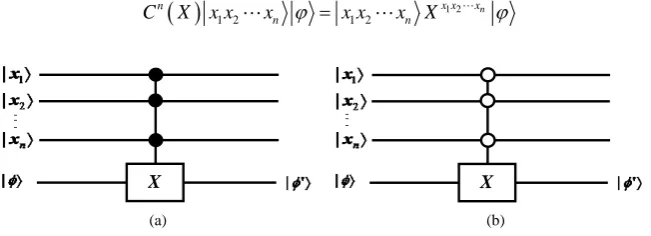
In a true quantum system, a single qubit state is often affected by a joint control of multi-qubits. A multi-qubits controlled-not gate Cn
( )
X is a kind of control model. The multi-qubits system is also described by the wave function x x1 2xn . In an (n + 1)-bits quantum system, when the target bit is simultaneously controlled by n input bits, the dynamic behavior of the system can be described by multi-qubits controlled-not gate in Figure 1.In Figure 1(a), suppose we have n + 1 qubits, and then we define the controlled operation Cn
( )
X as fol-lows( )
1 21 2 1 2
n
x x x n
n n
C X x x x ϕ = x x x X ϕ (6)
X
X
[image:3.595.152.478.591.709.2](a) (b)
Suppose that the xi =ai 0 +bi 1 are the control qubits, and the φ =c0 +d 1 is the target qubit. From Equation (6), the output of Cn(X) is written by equation
( )
1 2
1 2 1 2 1 2
1 2 1 2
11 10 11 10
11 11 11 11
n
n
n n
n n n
n n
n n
C X x x x
x x x b b b c b b b d
b b b c b b b d φ
φ
= ⊗ ⊗ ⊗ ⊗ − +
+ −
(7)
It is observed from Equation (7) that the output of Cn
( )
X is in the entangled state of n + 1 qubits, and the probability of the target qubit state ϕ , in which 1 is observed, equals to(
)
2(
2 2)
21 2 n
P= b bb c −d +d (8) In Figure 1(b), the operator X is applied to last a qubit if the first n qubits are all equal to zero, and otherwise, nothing is done. The controlled operation Cn
( )
X can be defined by the equation( )
1 21 2 1 2
n
x x x n
n n
C X x x x ϕ = x x x X φ (9) The probability of the target qubit state ϕ , in which 1 is observed, equals to
(
)
2(
2 2)
21 2 n
P= a a a c −d +d (8) At this time, after the joint control of the n input bits, the target bit φ′ can be defined as follows
1 P 0 P 1
φ′ = − + (9)
3. QNNSI Model
3.1. Quantum-Inspired Neuron Model
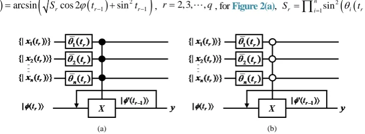
In this section, we first propose a quantum-inspired neuron model with sequence input, as shown in Figure 2. This model consists of quantum rotation gates and multi-qubits controlled-not gate. The
{
xi( )
tr}
defined in time domain interval [0, T] denote the input sequences. The output is the probability amplitude of the target state in 1 . The control parameters are the rotation angles θi( )
tr .Let x ti
( )
r =cosθi( )
tr 0 +sinθi( )
tr 1 , φ( )
t1 = 0 . In this paper, we define the output of the quantum neuron as the probability amplitude of the corresponding state, in which 1 is observed. According to the defi-nition of quantum rotation gate and multi-qubits controlled-not gate, the output of quantum neuron can be writ-ten as( )
( )
(
2)
1 1
cos 2 sin
q q q
y= S ϕ t − + ϕ t− (10)
where ϕ
( )
tr =arcsin(
Srcos 2ϕ( )
tr−1 +sin2tr−1)
, r=2, 3,,q, for Figure 2(a),(
( )
( )
)
21sin
n
r i i r i r
S =
∏
= θ t +θ t ,X
X
[image:4.595.133.495.573.706.2]
(a) (b)
for Figure 2(b), r n1cos2
(
i( )
r i( )
r)
i
S =
∏
= θ t +θ t .3.2. Quantum-Inspired Neural Network Model
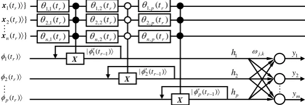
In this paper, the QNNSI model is shown in Figure 3, where the hidden layer consists of quantum-inspired neurons with sequence input, and the output layer consists of classical neurons. The
{
x ti( )
r}
denote the input sequences, the h h1, 2,,hp denote the hidden output, the ωjk denotes the connection weights in output layer, and the y y1, 2,,ym denote the network output. The Sigmoid function is used in output layer.Unlike ANN, each input sample of QNNSI is described as a matrix instead of a vector. For example, the l-th sample can be written as
( )
{
}
( )
{
}
( )
{
}
( )
( )
( )
( )
( )
( )
( )
( )
( )
1 1 1 1 2 1
2 1 2 2 2
2
1 1
l l l l
r q
l l l
l
q r
l l l
l
n n n q
n r
x t x t x t x t x t x t x t x t
x t x t x t x t = (11)
Let
( )
1 0, 1, 2, ,l
j t j p
ϕ = = ,
( )
( )
(
)
( )
( )
(
)
1 1sin , 1, 3, 5,
cos , 2, 4, 6,
n l
i r ij r i
jr n
l
i r ij r i
t t j h
t t j
θ θ θ θ = = + = = + =
∏
∏
, According to the input/
output relationship of quantum-inspired neuron, in interval
[ ]
0,tr , the spatial and temporal aggregation results of the j-th quantum-inspired neuron in hidden layer can be written as( )
( )
( )
(
(
( )
)
)
(
( )
)
1 1
2 2 2
1 1
1 2
l l
j j
l l l l
j r jr j r j r
h t h
h t h h t− h t−
= = − + (12)
The j-th output in hidden layer (namely, the spatial and temporal aggregation results in [0, T]) is given by
( )
l l
j j q
h =h t (13) The k-th output in output layer can be written as
1 1 1 e p l jk j j h l k
y =ω
− −∑
= +
(14)
4. QNNSI Algorithm
4.1. Pretreatment of Input and Output Samples
Suppose the l-th sample in n-dimensional input space
{
Xl( )
tr}
= x1l( )
tr ,x2l( )
tr ,,xnl( )
tr T, where r= [image:5.595.159.474.599.708.2]1, 2,,q, l=1, 2,,L. Let
Figure 3.The model of quantum-inspired neural network with sequence input. )
(
1 , 1 tr
θ
) (
1 , 2 tr
θ ) ( 1 , r n t θ
θ2,2(tr) θ2,p(tr)
) (
,p r n t θ } ) ( {|x1tr 〉
} ) ( {|xn tr 〉
〉 ) ( |φ1tr
〉 ) ( |φ2tr
〉 ) ( |φp tr
1 h 2 h p h 〉 ′( −) |φ1tr1
〉 ′( −) |φ2tr1
〉 ′( −) |φptr1
1 y 2 y m y k j, ω X X X ) ( , 1p tr
θ }
) ( {|x2 tr 〉
) ( 2 , r n t θ ) ( 2 , 1 tr
( )
( )
( )
(
)
( )
( )
( )
(
)
1 2 1 2Max max , , ,
Min min , , ,
L
ir i r i r i r
L
ir i r i r i r
x t x t x t x t x t x t
= =
(15)
( )
( )
Min πif Max Min Max Min 2
π
if Max Min 0 2
0 if Max Min 0
l
i r ir
ir ir
ir ir
l
i r ir ir
ir ir x t t θ − > − = = ≠ = = (16)
These samples can be converted into the quantum states as follows
( )
{
}
{
( )
}
{
( )
}
{
( )
}
T1 , 2 , ,
l l l l
r r r n r
X t = x t x t x t (17) where x til
( )
r =cos(
θil( )
tr)
0 +cos(
θil( )
tr)
1 .Similarly, suppose the l-th output sample
{ } { } { } { }
1 , 2 , , Tl l l l
m
Y = y y y , where l=1, 2,,L. Let
(
)
(
)
1 2
1 2 Max max , , ,
Min min , , ,
L
k k k k
L
k k k k
y y x y y x
= =
(18)
then, these output samples can be normalized by the following equation
Min
if Max Min Max Min
1 if Max Min 0
0 if Max Min 0
l
k k
ir ir
k k
l
k ir ir
ir ir y y − > − = = ≠ = = (19)
4.2. QNNSI Parameters Adjustment
In QNNSI, the adjustable parameters include the rotation angles of quantum rotation gates in hidden layer, and the weights in output layer. Suppose y1l,y2l,,yml denote the normalized desired outputs of the l-th sample, and y y1l, 2l,,yml denote the corresponding actual outputs. The evaluation function is defined as follows
1 1 1 1
max max lk max max kl lk l L k m l L k m
E e y y
≤ ≤ ≤ ≤ ≤ ≤ ≤ ≤
= = − (20)
Let
( )
( )
(
)
( )
( )
(
)
( )
(
(
( )
)
)
1 1 2 2 1sin 1, 2, 5,
cos 2, 4, 6,
1 2
n l
i r ij r i
l
jr n
l
i r ij r i
l l l
jr jr j r
t t j h
t t j S h h t
θ θ θ θ = = − + = = + = = −
∏
∏
(21)
According to the gradient descent algorithm in Ref. [16], the gradient of the rotation angles of the quantum rotation gates can be calculated as follows
( )
(
)
(
( )
)
( )
( )
(
(
( )
)
)
(
( )
)
( )
2 2 2
1 1
1
1 1 2 1 2 cot
l
q q
l l l l l l l l
k
k k jk s r js j s jr j r i r s r j s
ij r
e
y y h h t h h t t h t
t ω θ
θ = + − − =
∂
= − − − −
∂
∏
∏
(22)where j=1, 2,, ;p k=1, 2,,m r; =1, 2,, ;q l=1, 2,,L.
(
1)
( )
ll l l
k
k k j q
jk
e
y y h t
ω
∂ = − −
∂ (23)
Because gradient calculation is more complicated, the standard gradient descent algorithm is not easy to con-verge. Hence we employ the Levenberg-Marquardt algorithm in Ref. [16] to adjust the QNNSI parameters.
Let P denote the parameter vector, e denote the error vector, and J denote the Jacobian matrix. p, e, and J are respectively defined as follows
( )
( )
( )
T
11 1 11 2 11 12
P = θ t ,θ t ,θnp tq ,ω ω, ,,ωpm (24)
( )
T 1 1
1 1
e P , , , , L, , L
m m
e e e e
= (25)
( )
( )
( )
( )
( )
( )
( )
( )
( )
1 1 1 1
1 1 1 1
11 1 11 1 11
1 1 1 1
11 1 11 1 11
1 1 1 1
11 1 11 1 11
11 1 11 1 11
J P
pm
m m m m
pm
L L L L
pm
L L L L
m m m m
pm
e e e e
t t
e e e e
t t
e e e e
t t
e e e e
t t
θ θ ω ω
θ θ ω ω
θ θ ω ω
θ θ ω ω
∂ ∂ ∂ ∂ ∂ ∂ ∂ ∂ ∂ ∂ ∂ ∂ ∂ ∂ ∂ ∂ = ∂ ∂ ∂ ∂ ∂ ∂ ∂ ∂ ∂ ∂ ∂ ∂ ∂ ∂ ∂ ∂ (26)
According to Levenberg-Marquardt algorithm, the QNNSI iterative equation is written as follows
( ) ( )
(
T)
1 T( ) ( )
1
Pt Pt J P J Pt t µtI J P e Pt t
−
+ = − + (27)
where t denotes the iterative steps, I denotes the unit matrix, and µt is a small positive number to ensure the matrix JT
( ) ( )
P J Pt t +µtI invertible.4.3. Stopping Criterion of QNNSI
If the value of the evaluation function E reaches the predefined precision within the preset maximum of iterative steps, then the execution of the algorithm is stopped, else the algorithm is not stopped until it reaches the prede-fined maximum of iterative steps.
5. Simulations
To examine the effectiveness of the proposed QNNSI, the time series prediction for Mackey-Glass is used to compare it with the ANN with a hidden layer in this section. In this experiment, we implement and investigate the QNNSI in Matlab (Version 7.1.0.246) on a Windows PC with 2.19 GHz CPU and 1.00 GB RAM. Our QNNSI has the same structure and parameters as the ANN in the simulations, and the same Levenberg-Mar- quardt algorithm [16] is applied in two models.
Mackey-Glass time series can be generated by the following iterative equation [17]
( ) ( )
1 10(
(
)
)
( )
1
ax t
x t x t bx t x t
τ τ
−
+ − = −
+ − (28) where t and τ are integers, a=0.2, b=0.3, τ =17, and x
( ) ( )
0 ∈ 0, 1 .From the above equation, we may obtain the time sequence
{ }
( )
1000 1t
con-sists of n input values and an output value.
Hence, there is only one output node in QNNSI and ANN. In order to fully compare the approximation ability of two models, the number of hidden nodes are respectively set to 10, 11,, 40. The predefined precision is set to 0.05, and the maximum of iterative steps is set to 100. The QNNSI rotation angles in hidden layer are initia-lized to random numbers in
(
−π 2, π 2)
, and the connection weights in output layer are initialized to random numbers in (−1, 1). For ANN, all weights are initialized to random numbers in (−1, 1), and the Sigmoid func-tions are used as the activation funcfunc-tions in hidden layer and output layer.Obviously, ANN has n input nodes, and an ANN’s input sample can be described as a n-dimensional vector. For the number of input nodes of QNNSI, we employ the following nine kinds of settings shown in Table 1. For each of these settings in Table 1, a single QNNSI input sample can be described as a matrix.
It is worth noting that, in QNNSI, an n q× matrix can be used to describe a single sequence sample. In gen-eral, ANN cannot deal directly with a single n q× sequence sample. In ANN, an n q× matrix is usually re-garded as nq dimensional vector samples. For fair comparison, in ANN, we have expressed the n q× se-quence samples into the nq dimensional vector samples. Therefore, in Table 1, the sequence lengths for ANN are not changed. It is clear that, in fact, there is only one kind of ANN inTable 1, namely, ANN36.
Our experiment scheme is that, for each kind of combination of input nodes and hidden nodes, one ANN and nine QNNSIs are respectively run 10 times. Then we use four indicators, such as average approximation error,
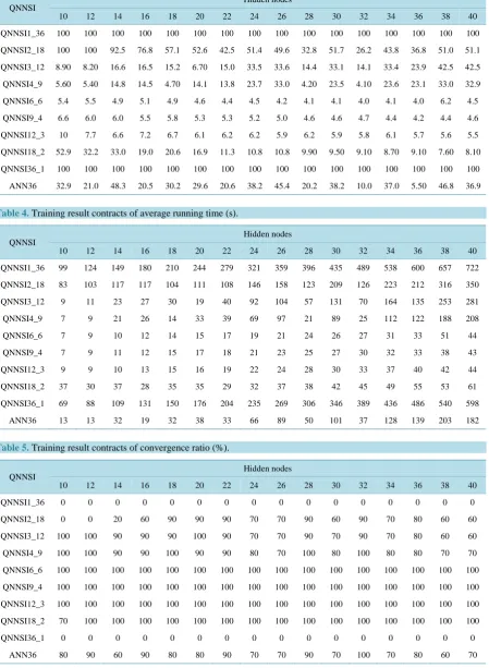
average iterative steps, average running time, and convergence ratio, to compare QNNSI with ANN. Training result contrasts are shown in Tables 2-5, where QNNSIn_q denotes QNNSI with n input nodes and q sequence length.
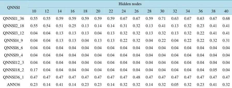
[image:8.595.89.534.360.521.2]FromTables 2-5, we can see that when the input nodes take 6, 9, and 12, the performance of QNNSIs are
Table 1.The input nodes and the sequence length setting of QNNSIs and ANN.
QNNSI ANN
Input nodes Sequence length Input nodes Sequence length
1 36 36 1
2 18 36 1
3 12 36 1
4 9 36 1
6 6 36 1
9 4 36 1
12 3 36 1
18 2 36 1
36 1 36 1
Table 2.Training result contracts of average approximation error.
QNNSI Hidden nodes
10 12 14 16 18 20 22 24 26 28 30 32 34 36 38 40
QNNSI1_36 0.55 0.55 0.59 0.59 0.59 0.59 0.59 0.67 0.67 0.59 0.71 0.63 0.67 0.63 0.67 0.68
QNNSI2_18 0.55 0.54 0.51 0.25 0.13 0.14 0.14 0.31 0.32 0.13 0.41 0.13 0.32 0.23 0.41 0.41
QNNSI3_12 0.04 0.04 0.13 0.13 0.13 0.04 0.13 0.32 0.32 0.13 0.32 0.13 0.32 0.22 0.41 0.41
QNNSI4_9 0.04 0.04 0.13 0.13 0.04 0.13 0.13 0.22 0.32 0.04 0.22 0.04 0.22 0.22 0.32 0.31
QNNSI6_6 0.04 0.04 0.04 0.04 0.04 0.04 0.04 0.04 0.04 0.04 0.04 0.04 0.04 0.04 0.04 0.04
QNNSI9_4 0.04 0.04 0.04 0.04 0.04 0.04 0.04 0.04 0.04 0.04 0.04 0.04 0.04 0.04 0.04 0.04
QNNSI12_3 0.04 0.04 0.04 0.04 0.04 0.04 0.04 0.04 0.04 0.04 0.04 0.04 0.04 0.04 0.04 0.04
QNNSI18_2 0.17 0.04 0.04 0.04 0.04 0.04 0.04 0.04 0.04 0.04 0.04 0.04 0.04 0.04 0.05 0.04
QNNSI36_1 0.47 0.47 0.47 0.47 0.47 0.47 0.47 0.47 0.48 0.47 0.47 0.47 0.47 0.47 0.47 0.47
[image:8.595.88.537.549.719.2]Table 3. Training result contracts of average iterative steps.
QNNSI
Hidden nodes
10 12 14 16 18 20 22 24 26 28 30 32 34 36 38 40
QNNSI1_36 100 100 100 100 100 100 100 100 100 100 100 100 100 100 100 100
QNNSI2_18 100 100 92.5 76.8 57.1 52.6 42.5 51.4 49.6 32.8 51.7 26.2 43.8 36.8 51.0 51.1
QNNSI3_12 8.90 8.20 16.6 16.5 15.2 6.70 15.0 33.5 33.6 14.4 33.1 14.1 33.4 23.9 42.5 42.5
QNNSI4_9 5.60 5.40 14.8 14.5 4.70 14.1 13.8 23.7 33.0 4.20 23.5 4.10 23.6 23.1 33.0 32.9
QNNSI6_6 5.4 5.5 4.9 5.1 4.9 4.6 4.4 4.5 4.2 4.1 4.1 4.0 4.1 4.0 6.2 4.5
QNNSI9_4 6.6 6.0 6.0 5.5 5.8 5.3 5.3 5.2 5.0 4.6 4.6 4.7 4.4 4.2 4.4 4.6
QNNSI12_3 10 7.7 6.6 7.2 6.7 6.1 6.2 6.2 5.9 6.2 5.9 5.8 6.1 5.7 5.6 5.5
QNNSI18_2 52.9 32.2 33.0 19.0 20.6 16.9 11.3 10.8 10.8 9.90 9.50 9.10 8.70 9.10 7.60 8.10
QNNSI36_1 100 100 100 100 100 100 100 100 100 100 100 100 100 100 100 100
[image:9.595.91.541.110.724.2]ANN36 32.9 21.0 48.3 20.5 30.2 29.6 20.6 38.2 45.4 20.2 38.2 10.0 37.0 5.50 46.8 36.9
Table 4. Training result contracts of average running time (s).
QNNSI
Hidden nodes
10 12 14 16 18 20 22 24 26 28 30 32 34 36 38 40
QNNSI1_36 99 124 149 180 210 244 279 321 359 396 435 489 538 600 657 722
QNNSI2_18 83 103 117 117 104 111 108 146 158 123 209 126 223 212 316 350
QNNSI3_12 9 11 23 27 30 19 40 92 104 57 131 70 164 135 253 281
QNNSI4_9 7 9 21 26 14 33 39 69 97 21 89 25 112 122 188 208
QNNSI6_6 7 9 10 12 14 15 17 19 21 24 26 27 31 33 51 44
QNNSI9_4 7 9 11 12 15 17 18 21 23 25 27 30 32 33 38 43
QNNSI12_3 9 9 10 13 15 16 19 22 24 28 30 33 37 40 42 44
QNNSI18_2 37 30 37 28 35 35 29 32 37 38 42 45 49 55 53 61
QNNSI36_1 69 88 109 131 150 176 204 235 269 306 346 389 436 486 540 598
[image:9.595.88.537.530.720.2]ANN36 13 13 32 19 32 38 33 66 89 50 101 37 128 139 203 182
Table 5. Training result contracts of convergence ratio (%).
QNNSI Hidden nodes
10 12 14 16 18 20 22 24 26 28 30 32 34 36 38 40
QNNSI1_36 0 0 0 0 0 0 0 0 0 0 0 0 0 0 0 0
QNNSI2_18 0 0 20 60 90 90 90 70 70 90 60 90 70 80 60 60
QNNSI3_12 100 100 90 90 90 100 90 70 70 90 70 90 70 80 60 60
QNNSI4_9 100 100 90 90 100 90 90 80 70 100 80 100 80 80 70 70
QNNSI6_6 100 100 100 100 100 100 100 100 100 100 100 100 100 100 100 100
QNNSI9_4 100 100 100 100 100 100 100 100 100 100 100 100 100 100 100 100
QNNSI12_3 100 100 100 100 100 100 100 100 100 100 100 100 100 100 100 100
QNNSI18_2 70 100 100 100 100 100 100 100 100 100 100 100 100 100 100 100
QNNSI36_1 0 0 0 0 0 0 0 0 0 0 0 0 0 0 0 0
obviously superior to that of ANN, and the QNNSIs have better stability than ANN when the number of hidden nodes changes.
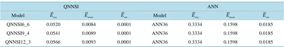
Next, we investigate the generalization ability of QNNSI. Based on the above experimental results, we only investigate three QNNSIs (QNNSI6_6, QNNSI9_4, and QNNSI12_3). Our experiment scheme is that three QNNSIs and one ANN train 10 times on the training set, and the generalization ability is immediately investi-gated on the testing set after each training. The average results of the 10 tests are regarded as the evaluation in-dexes. For convenience of description, let Eavg denote the average of the maximum prediction error, Emean denote the average of the prediction error mean, and Evar denote the average of prediction error variance.
Taking 30 hidden nodes for example, the evaluation indexes contrast of QNNSIs and ANN are shown in Ta-ble 6. The experimental results show that the generalization ability of three QNNSIs is obviously superior to that of corresponding ANN.
These experimental results can be explained as follows. For processing of input information, QNNSI and ANN take different approaches. QNNSI directly receives a discrete input sequence. In QNNSI, using quantum information processing mechanism, the input is circularly mapped to the output of quantum controlled-not gates in hidden layer. As the controlled-not gate’s output is in the entangled state of multi-qubits, therefore, this map-ping is highly nonlinear, which make QNNSI have the stronger approximation ability. In addition, QNNSI’s each input sample can be described as a matrix with n rows and q columns. It is clear from QNNSI’s algorithm that, for the different combination of n and q, the output of quantum-inspired neuron in hidden layer is also dif-ferent. In fact, The number of discrete points q denotes the depth of pattern memory, and the number of input nodes n denotes the breadth of pattern memory. When the depth and the breadth are appropriately matched, the QNNSI shows excellent performance. For the ANN, because its input can only be described as a nq-dimensional vector, it is not directly deal with a discrete input sequence. Namely, it only can obtain the sample characteristics by way of breadth instead of depth. Hence, in the ANN information processing, there exists inevitably the loss of sample characteristics, which affects its approximation and generalization ability.
It is worth pointing out that QNNSI is potentially much more computationally efficient than all the models referenced above in the Introduction section. The efficiency of many quantum algorithms comes directly from quantum parallelism that is a fundamental feature of many quantum algorithms. Heuristically, and at the risk of over-simplifying, quantum parallelism allows quantum computers to evaluate a function f(x) for many different values of x simultaneously. Although quantum simulation requires many resources in general, quantum paral-lelism leads to very high computational efficiency by using the superposition of quantum states. In QNNSI, the input samples have been converted into corresponding quantum superposition states after preprocessing. Hence, as far as a lot of quantum rotation gates and controlled-not gates used in QNNSI are concerned, information processing can be performed simultaneously, which greatly improves the computational efficiency. Because the above experiments are performed in classical computer, the quantum parallelism has not been explored. How-ever, the efficient computational ability of QNNSI is bound to stand out in future quantum computer.
6. Conclusion
This paper proposes quantum-inspired neural network model with sequence input based on the principle of quantum computing. The architecture of the proposed model includes three layers, where the hidden layer con-sists of quantum-inspired neurons and the output layer concon-sists of classical neurons. An obvious difference from classical ANN is that each dimension of a single input sample consists of a discrete sequence rather than a single value. The activation function of hidden layer is redesigned according to the principle of quantum computing. The
[image:10.595.87.539.644.720.2]Levenberg-Marquardt algorithm is employed for learning. With application of the information processing mechan-ism of quantum rotation gates and controlled-not gates, the proposed model can effectively obtain the sample
Table 6.The average prediction error contrasts of QNNSIs and ANN.
QNNSI ANN
Model Eavg Emean Evar Model Eavg Emean Evar
QNNSI6_6 0.0520 0.0084 0.0001 ANN36 0.3334 0.1598 0.0185
QNNSI9_4 0.0541 0.0089 0.0001 ANN36 0.3334 0.1598 0.0185
characteristics by ways of breadth and depth. The experimental results reveal that a greater difference between input nodes and sequence length leads to a lower performance of proposed model than that of classical ANN; on the contrary, it obviously enhances approximation and generalization ability of proposed model when input nodes are closer to sequence length. The following issues of the proposed model, such as continuity, computa-tional complexity, and improvement of learning algorithm, are subjects of further research.
Acknowledgements
This work was supported by the National Natural Science Foundation of China (Grant No. 61170132), Natural Science Foundation of Heilongjiang Province of China (Grant No. F2015021), Science Technology Research Project of Heilongjiang Educational Committee of China (Grant No. 12541059), and Youth Foundation of Northeast Petroleum University (Grant No. 2013NQ119).
References
[1] Tsoi, A.C. and Back, A.D. (1994) Locally Recurrent Globally Feed Forward Network: A Critical Review of Architec-tures. IEEE Transactions on Neural Network, 7, 229-239. http://dx.doi.org/10.1109/72.279187
[2] Kleinfeld, A.D. (1986) Sequential State Generation by Model Neural Network. Proceedings of the National Academy of Sciences USA, 83, 9469-9473. http://dx.doi.org/10.1073/pnas.83.24.9469
[3] Waibel, A., Hanazawa, A. and Hinton, A. (1989) Phoneme Recognition Using Time-Delay Neural Network. IEEE Transactions on Acoustics, Speech, and Signal Processing, 37, 328-339. http://dx.doi.org/10.1109/29.21701
[4] Lippmann, R.P. (1989) Review of Neural Network for Speech Recognition. Neural Computation, 1, 1-38. http://dx.doi.org/10.1162/neco.1989.1.1.1
[5] Maria, M., Marios, A. and Chris, C. (2011) Artificial Neural Network for Earthquake Prediction Using Time Series Magnitude Data or Seismic Electric Signals. Expert Systems with Applications, 38, 15032-15039.
http://dx.doi.org/10.1016/j.eswa.2011.05.043
[6] Kak, S. (1995) On Quantum Neural Computing. Information Sciences, 83, 143-160. http://dx.doi.org/10.1016/0020-0255(94)00095-S
[7] Gopathy, P. and Nicolaos, B.K. (1997) Quantum Neural Network (QNN's): Inherently Fuzzy Feed forward Neural Network. IEEE Transactions on Neural Network, 8, 679-693. http://dx.doi.org/10.1109/72.572106
[8] Zak, M. and Williams, C.P. (1998) Quantum Neural Nets. International Journal of Theoretical Physics, 3, 651-684. http://dx.doi.org/10.1023/A:1026656110699
[9] Maeda, M., Suenaga, M. and Miyajima, H. (2007) Qubit Neuron According to Quantum Circuit for XOR Problem. Applied Mathematics and Computation, 185, 1015-1025. http://dx.doi.org/10.1016/j.amc.2006.07.046
[10] Gupta, S. and Zia, R.K. (2001) Quantum Neural Network. Journal of Computer and System Sciences, 63, 355-383. http://dx.doi.org/10.1006/jcss.2001.1769
[11] Shafee, F. (2007) Neural Network with Quantum Gated Nodes. Engineering Applications of Artificial Intelligence, 20, 429-437. http://dx.doi.org/10.1016/j.engappai.2006.09.004
[12] Li, P.C., Song, K.P. and Yang, E.L. (2010) Model and Algorithm of Neural Network with Quantum Gated Nodes. Neural Network World, 11, 189-206.
[13] Adenilton, J., Wilson, R. and Teresa, B. (2012) Classical and Superposed Learning for Quantum Weightless Neural Network. Neurocomputing, 75, 52-60. http://dx.doi.org/10.1016/j.neucom.2011.03.055
[14] Israel, G.C., Angel, G.C. and Belen, R.M. (2012) Dealing with Limited Data in Ballistic Impact Scenarios: An Empir-ical Comparison of Different Neural Network Approaches. Applied Intelligence, 35, 89-109.
[15] Israel, G.C., Angel, G.C. and Belen, R.M. (2013) An Optimization Methodology for Machine Learning Strategies and Regression Problems in Ballistic Impact Scenarios. Applied Intelligence, 36, 424-441.
[16] Martin, T.H., Howard, B.D. and Mark, H.B. (1996) Neural Network Design. PWS Publishing Company, Boston, 391- 399.