© 2016, IRJET | Impact Factor value: 4.45 | ISO 9001:2008 Certified Journal | Page 2579
DESIGN AND STATIC ANALYSIS OF COMPOSITE LEAF SPRING
FOR HEAVY VEHICLE
S. Surya teja
1, K. Sambasivarao
2, I. Anil kumar
31M.Tech, student (Machine Design),
2, 3 Assistant Professor, Mechanical Engineering Dept, Swamy Vivekananda engineering college, Bobbili (India)
---***---Abstract - The automobile industry has shown increased
interested in the replacement of steel spring with e glass epoxy leaf spring due to high strength to weight ratio the aim of this project is to present low cost fabrication of e glass epoxy leaf spring with end joints and also general study on the design by using CATIA V5R19 123 and ANSYS12.0 A single leaf with variable thickness and width of constant cross sectional area Epoxy glass leaf spring with similar mechanical and Geometrical properties of Multi leaf spring Compared to the steel spring, the Composite spring ha stresses that are Much lower, the natural frequency is higher and The spring weight is nearly 85 % lower with bonded end joint and with complete eye Bonded end joint unit.
1.INTRODUCTION
A spring is defined as an elastic body, whose function is to distort when the load is removed its original shape when the load is removed. Springs are unlike other structure components in that they undergo significant deformation when loaded their compliance enables them to store readily recoverable mechanical energy. In a vehicle suspension, when the wheel meets an obstacle, the springing allows movement of wheel over the obstacle and thereafter returns the wheel to its normal position.
The simplest spring is the tension bar. This is an efficient energy store since all its elements are stressed identically, but its deformation is small if it is made of metal. Unlike the constant cross-section beam the leaf spring is stressed almost constantly along its length because the linear increase of bending movement either simple support is matched by the beam’s widening.
Semi-elliptical leaf springs are almost universally used for suspension. The laminated spring consists of number of leaves called blades. The blades are varying in length curvature so that they will tend to straighten under the load. The leaf spring is design is based upon the theory of beams of uniforms strength.
Leaf springs are essential elements in the suspension systems of vehicles. Accurate modeling of leaf springs is necessary in evaluating ride comfort, braking performance, vibration characteristics and stability. Through simple in appearance, a leaf spring suspension causes many problems in modeling. For dynamic simulation the vehicles are usually modeled by multi-body-systems (MBS).For realistic ride and handling, simulations of the leaf springs must be taken into account. The objective of this study has been to find an efficient FE method for the analysis of the laminated leaf springs, which allows for fast analyses and easy implementation.
Fig1: Laminated leaf spring
1.1Suspension Model
All suspension systems contain two main ingredients, a spring component and a damper component. The suspension’s main purpose is to filter out axle excitation before these disturbances reach the chassis. There is a verity of different suspensions used on vehicles. However, some types of suspensions have grown more pop lour than others .In the truck /car industry the overwhelming majority are leaf springs.
© 2016, IRJET | Impact Factor value: 4.45 | ISO 9001:2008 Certified Journal | Page 2580
1.1.1 Leaf Spring Suspension.
a) Single axle leaf spring.
b) Tandem leaf spring/short rocker.
c) Tridem leaf spring/short rocker.
1.1.2 Leaf Spring Model
Leaves are made up laminated strips of curved steel. The chassis supports the two ends and middle of the spring is connected to the axle as the leaf spring is compressed, the steel leaves bend acting as springs, and leaves slide across each other dissipating energy through coulomb friction. The mathematical leaf-spring model used in this study is the semi-analytic model
based on the Euler beam theory.
Fig1 leaf spring models
1.1.3 Four basic types of leaf spring systems
1.Multi-leaf spring – This type of leaf spring has more
than 1 leaf in its assembly. It consists of a center bolt that properly aligns the leaves and clips to resist its individual leaves from twisting and shifting.
2. Mono leaf spring – Consists of one main leaf where the material’s width and thickness are constant.
Example- the leaf will be 2 ½” wide throughout its entire length. The spring rate is lighter than others styles of leaf springs and usually requires a device to control positive and negative torque loads as well as requiring coil springs to hold the chassis at ride height.
3. Parabolic Single leaf – Consists of one main leaf
with a tapered thickness. This style is sufficient to control axle torque and dampening, while maintain ride height. The advantage of this style is that the spring is lighter than the multi-leaf.
4. Fiberglass Leaf spring – the fiberglass leaf spring is
made of mixture of plastic fibers and resin; it is lighter than all other springs. However, the cost is three times greater. In addition, fiberglass springs are sensitive to heat.
Fig2:Double-Eye Spring Slipper Radius-End Springs
Fig 3:Slipper Open-Eye Springs Slipper Flat-End
1.1.4 Leaf Spring Rate
© 2016, IRJET | Impact Factor value: 4.45 | ISO 9001:2008 Certified Journal | Page 2581 positions of spring, and is different for the spring as
installed Static deflection of a spring equals the static load divided by the rate at static load; it determines the stiffness of the suspension and the ride frequency of the vehicle. In the most cases the static deflection differs from the actual deflection of the spring between zero and static load, due to influences of spring camber and shackle effect.
1.1.5 Characteristics Of A Good Suspension Include
Maximum deflection consistent with required stability
Compatible with other vehicle components in terms of over all ride
Minimum weight
Low maintenances and operating costs Minimize tire wear
Minimize wheel hop Low initial cost
1.1.6 Functions Of Leaf Springs In Design Performs
Support the weight of the vehicle.
Provide adequate stability and resistance to side away and rollover.
Resist cornering effects when negotiating a curve.
Provide cushioining
1.2 Contact Overview:
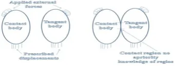
Contact problems are highly nonlinear and require significant computer resources to solve. It is important to understand the physics of the problem and take the time to set up the model to run as efficiently as possible. Contact problems present two significant difficulties. First, we generally do not know the regions of contact until we run the problem. Depending on loads, materials, boundary conditions, and other factors, surfaces come into and go out of contact with each other in largely unpredictable and abrupt manner. Second, most contact problems need to account for friction. There are several friction laws and models to choose from. And all are nonlinear. Frictional response can be chaotic, making solution convergence difficult.
1.2.1 General contact classification:
Contact problems fall into two general classes: rigid-to-flexible and rigid-to-flexible-to-rigid-to-flexible contact problems, one or more of the contacting surfaces are treated as rigid (i.e., it has a much higher stiffness relative to the deformable body it contacts). In general, any time a soft material comes in contact with a hard material, the
problem may be assumed to rigid-to-flexible. Many metal forming problems fall into this category. The other class, flexible-to-flexible, is the more common type. In this case, both (or all) contacting bodies are deformable (i.e., have similar stiffness). An example of a flexible-to-flexible contact is bolted flanges.
Fig 4:Schematic representation of the bi-dimensional
contact problem
1.3 Quality and Workmanship of Leaf Springs:
1.Centerhole:
If made with good dies, it will be clean-cut. A poor center hole may set up additional stresses in the steel, which may cause premature breakage.
2. Trim points:
Must be done with good equipment, to avoid cracking, chipping and rough edges.
3. Clips:
Must be right size and shape to fit properly.
4. Eyes:
Must be tight accurately sized; must be parallel and straight, to avoid setting up excess stresses in the main leaf. If the eye is too small, the bushing may be crushed when forced in. If the eye is too large, the bushing will be loose.
5. Fitting of leaves:
Must be accurate, to avoid setting up excess stresses in steel and causing premature breakage.
6. Leaves:
Must be fitted side to side, as well as surface to surface.
2.1 Problem definition:
[image:3.595.361.532.195.261.2]© 2016, IRJET | Impact Factor value: 4.45 | ISO 9001:2008 Certified Journal | Page 2582 leaf spring suspension causes many problems in
modeling.
The establishment and evolution of the finite element method (FEM) has contributed greatly to the solution of many engineering problems, particularly in situations where analytical methods become too complex, and experimental techniques appear inappropriate because of either difficulty in application or instrumentation, or of the high costs which may be involved. One pronounced advantages of FEM lies in the fact that it can be used to solve a class of problems with only minor modifications once the model, boundary conditions, and accuracy have been tested and proven. The increasing computing power associated with faster processor speed and greater data storage capacity has also been a catalyst in developing FE applications.
2.2 Problem Statement:-
There is currently much interest in deformation analysis of multiple bodies in contact. One such case is the design and analysis of the automobile leaf springs. In order to accurately model the deformations and vibrations of the leaf springs nonlinear finite-element procedures are need to be employed with the advent of development of the contact analysis it is appropriate to apply the contact analysis technique in the analysis of the leaf springs. Methods for modeling the contact and friction between leaves of the spring are to be developed. Thus it is appropriate to have perfect non-linear finite element method to analyze the leaf springs. Effect of varying different parameters life width, length and thickness of the leaf spring are to be investigated with the help of the commercial FEM package ANSYS.
Fig 5:Design of leaf spring
And with using ansys compare the results of structural steel and e-glass epoxy are
3.1 Material properties for structural steel:
Fig 6: Material properties for structural
steel
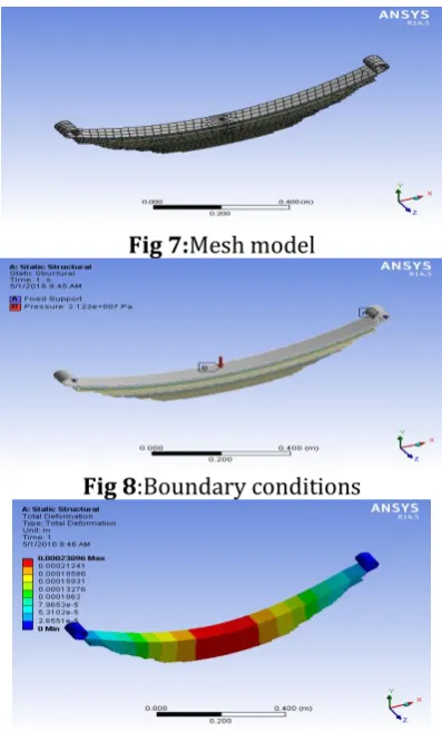
Fig 7:Mesh model
Fig 8:Boundary conditions
[image:4.595.360.534.98.249.2] [image:4.595.334.533.300.638.2] [image:4.595.91.283.563.677.2]© 2016, IRJET | Impact Factor value: 4.45 | ISO 9001:2008 Certified Journal | Page 2583
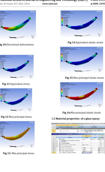
Fig 10:Directional deformation
Fig 11:Equivalent stress
Fig 12:Max principal stress
Fig 13: Min principal stress
Fig 14:Equivalent elastic strain
[image:5.595.95.531.56.766.2]Fig 15:Max principal elastic strain
Fig 16:Min principal elastic strain
[image:5.595.311.533.547.691.2]© 2016, IRJET | Impact Factor value: 4.45 | ISO 9001:2008 Certified Journal | Page 2584
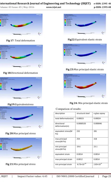
[image:6.595.74.545.41.815.2]Fig 17: Total deformation
Fig 18:Directional deformation
Fig19:Equivalentstress
[image:6.595.341.525.351.459.2]Fig 20:Max principal stress
Fig 21:Min principal stress
Fig22:Equivalent elastic strain
Fig 23:Max principal elastic strain
Fig 24: Min principal elastic strain
Comparison of results:
description structural steel e glass epoxy
total deformation(m) 0.00023 0.00024
directional deformation(m)
0.0000520 0.000046
equivalent stress(M Pa)
232 281
max principal stress(M Pa)
254 318
min principal stress(M Pa)
19.6 23.1
equivalent strain 0.0014 0.0014
max principal strain 0.0012 0.0014
[image:6.595.302.538.510.757.2]© 2016, IRJET | Impact Factor value: 4.45 | ISO 9001:2008 Certified Journal | Page 2585
3. CONCLUSIONS
Structural steel and e glass epoxy resins deformation,
stress and strain values are tabulated e glass epoxy resins have
little deformation, max stress and less strain so fabrication of
leaf spring by using e glass epoxy resins are best suited
Future work:
The future work of this project is to produce with fewer prices and that material should have required stresses should with stand these loads and that material also have elastic properties and should have good suspension.
ACKNOWLEDGEMENT
I would like to thank Department of mechanical Engineering staff and management of Swamy Vivekananda engineering college, Bobbili (India) for their support in doing this work.
REFERENCES
[1]. Rajendran, I., Vijayarangan, S. Optimal Design of a Composite Leaf Spring using Genetic Algorithms Int. Jr. of
Computer and Structures 79 2001: pp. 1121 – 1129.
[2]. Rajendran, I., Vijayarangan, S. Design and Analysis of a Composite Leaf Spring Journal of Institute of Engineers India 82 2002: pp. 180 – 187.
[3]. Daugherty, R. L. Composite Leaf Springs in Heavy Truck Applications. K. Kawata, T.Akasaka (Eds). Composite Materials
Proceedings of Japan-US Conference Tokyo, 1981: pp. 529 –
538.
[4]. Dharam, C. K. Composite Materials Design and Processes for Automotive Applications. The ASME Winter Annual Meeting, San Francisco, December 10-15, 1978: pp. 19 – 30. [5]. Vijayarangan, S., Ganesan, N. Static Stress Analysis of a Composite Bevel Gear using a Three-dimensional Finite Element Method Computer Structures 51 (6) 1994:pp. 771 – 783.
[6]. Tanabe, K., Seino, T., Kajio, Y. Characteristics of Carbon/Glass Fiber Reinforced Plastic Leaf Spring, SAE 820403 1982: pp. 1628 – 1634.
[7]. Yu, W. J., Kim, H. C. Double Tapered FRP Beam for Automobile Suspension Leaf Spring Comp. Structure 1998: pp. 279 – 300.
[8]. Jones, R. M. Mechanics of Composite Materials. 2e, Mc Graw-Hill Book Company, 1990.